Chapter 11 – Elevators installed

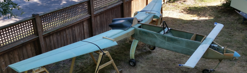
Ok, finally today was the day for the final installation of the elevators onto the canard.

Yesterday, after a good bit of prepping, I realized that the end of each elevator pin was gnarled from too many sessions of using vise grips on the end of them to extract them during the dark ages when it was far, far too difficult to remove the hinge pins.  So, I took the hinge pins back to my shop and cleaned them up there… after getting the canard situated at an angle inside the hangar to allow enough clearance for said hinge pins to be inserted into place.

Back to today, as you can see, using patience and continuing to work through all the minor issues I was able to get the elevators installed in about 2.5 hours.  To be clear, I do still need to install the 10-32 set screws on the outboard end of each elevator to secure the hinge pin from coming out (if that is even possible!)… but, not only did I not have a 3/32″ hex key (the only missing in the set I brought <sigh>), but the longer set screws I brought were also 1/4″, not 10-32.

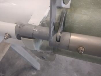
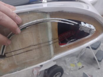
The one significant issue I had after installing the elevators was that at this exact pivot point the nose of the left elevator outboard weight catches on the front vertical wall of the weight pocket in the canard.  I’ll deal with that tomorrow to get the elevator pivoting freely and unencumbered.

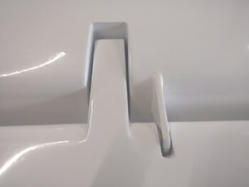
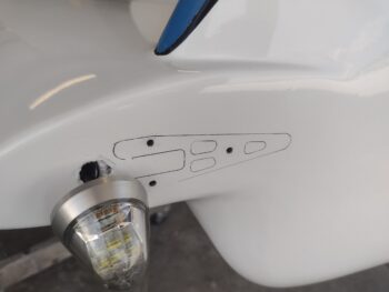
The good news, visible in this picture, is that ALL the thin washers are installed on the elevator hinge tabs, one on each side.  This is the left outboard hinge tab.

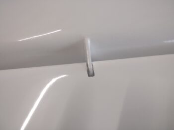
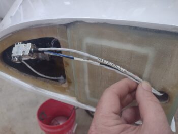
A couple more proof-positive pics showing confirmation of the installed washers, with them on each side of the left middle hinge tab (pic 1) and the right inboard hinge tab (pic 2).  For those of you that have had to install these washers, you know what a challenging feat it is to get these little suckers into place.

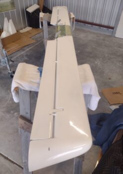
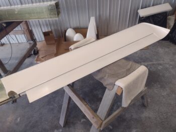
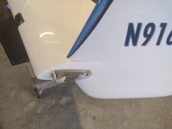
And a couple solo shots of the left (pic 1) and right (pic 2) elevators mounted to the canard.

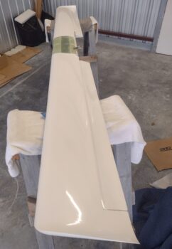
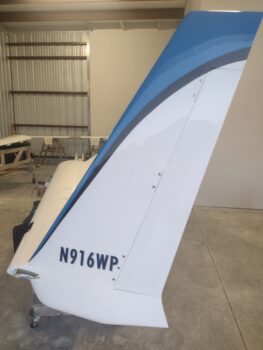
And here we have the canard turned upright with the newly installed elevators in tow.

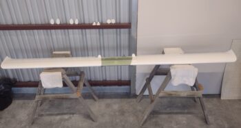
And one final canard shot with the elevators not really visible…

Tomorrow I plan on getting those set screws installed before I head to the shop and focus on the AILERON weight and balance.

Yep, still pressing onward!

Chapter 19 – Aileron Weight & Balance

I started out today by heading to the hangar with the intent of installing the elevators first and then heading back to my shop to knock out the weight and balance of the ailerons.  Alas, between not having all the tools on hand that I needed, helping Guy with some stuff on his Long-EZ, and generally BS’ing with some fellow EAA’ers, I didn’t get back to my shop until very late afternoon.

I then did a few hours of final research in the original LEZ plans, on the COBA forum and in my Central States Association searchable newsletters to ensure I was armed with the all the knowledge I could cram into my head regarding balancing the ailerons.

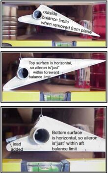
Here’s the skinny from a CSA article on what the parameters and final goal is in balancing the ailerons.

Are my ailerons, like so many other builders, represented by the one in the middle? (note: “sarcasm”).

In one CSA article Joe Person was relaying a statement by Valerie Jarret where she noted that 9 out of 10 canard aircraft they worked on did not have balanced flight controls.  IN MY OPINION, it is quite likely that both in the building and original design features of the ailerons it is near impossible to see anything near an aileron as shown in the middle picture without possibly having missed a layup ply when built.

To drive this point home, even Klaus Savier, who is maniacal when it comes to weight, noted that his original Vari-Eze ailerons were well over 6 lbs. a piece.  As there is no aileron weight parameters identified in the plans, the only other official weight reference we have is out of the Canard Pusher Newsletters that list Mike Melvill’s aileron weight at 5 lbs 2 oz before paint.

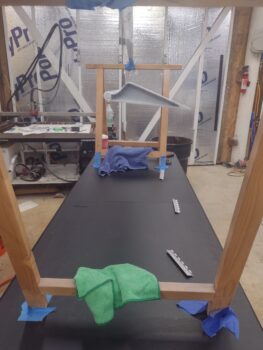
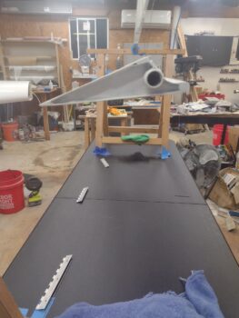
How about my ailerons?  Here is my left side aileron.  Pic 1 is the better representation of the angle vs pic 2, which the camera itself is at an angle.

I will set up a level just under the bottom surface of the aileron, but the bottom line is that my ailerons are NOT balanced, and will need added weight attached to the top of the leading edges to bring them into balance.  The max allowable weight to add per plans is 0.3 lbs.

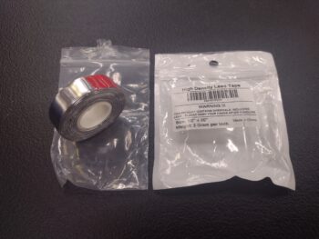
Now, I ordered adhesive backed lead tape to use for this purpose, but I didn’t account for the total weight possibly required when I ordered this one roll many moons ago, as it is only a bit over 0.25 lbs total and I’ll need at least double that to get my ailerons balanced.

Thus, I pulled the trigger on another roll of adhesive lead weight and called it a night.

Inching forward . . .

Chapter 11 – Elevator Weight & Balance

Today was elevator day where I focused on the weight and balancing of both elevators.  I made a video detailing how and what I did for the elevator weight and balance, which explains all that I have to communicate.  Enjoy.

Tomorrow I plan on transporting the elevators to the hangar along with the tools to install them onto the canard.  I also plan on starting on the final aileron weight and balance as well.

Pressing forward!

Chapter 20/22 – Rudders installed

Today I had 2 goals, both involving work at the hangar.

First, I needed to get the left wingtip nav/strobe light bracket set in place to allow me to install the nav/strobe light without an egregious gap between the light and wing tip edge.

I started that task off by first tracing the mounted light bracket so I could then remove paint, primer and micro as required —mostly towards the top and aft edge of the bracket— to get the light to sit <more> flush on the wing end surface.

Although I had used a flat sanding block specifically to create a flat light mounting surface during the finishing process, there was still an ever so slight contour to it and the light just was not having it… refusing to engage and slide down the 3 mounting tabs to secure it in place BEFORE the aft side setscrew was seated.

After literally hours of messing around with it, I finally minimized the top aft gap between nav/strobe light assembly and the wing tip edge by essentially transferring that gap to the bottom of the light.  After multiple hours of messing with it to no avail, I begrudgingly accepted this compromise to get this task done and move on with things… simply wanting to first ensure the light was actually installed and secured, since I was already down to glass on a good swath below the upper side of the bracket and running out of contour options for seating the bracket.

I had been taking breaks throughout the day to help Guy Williams down at his hangar with his Long-EZ (also chit-chatting with other EAA members) and just after I finally got the left wingtip nav/strobe light installed, Guy arrived at my hangar.

Goal #2 for the day was to get the rudders installed into the winglets and working properly.

Guy helped me install the left rudder and ensure that it wasn’t binding internally and seated in place properly (after paint) in the closed position.

Guy then helped me remove the right rudder since it was not fully closing as it was binding internally and needed some judicious sanding … which I did.  We then re-installed the right rudder temporarily to test out that it was seating fully closed after the sanding, which it was.

We then pulled the rudder off again, attached the rudder cable to the hidden belhorn with clevis and cotter pin before installing it back into the winglet a final time.

I will note that the rudder return springs are NOT installed into either the left or right aft rudder pockets, as I have not connected them yet to the rudders since I want to 3D print some protective edge sleeves for both the rudder and winglet mating edges to ensure that the paint does not get chipped during the spring install onto the rudder side hook.  That task should be coming within the next few days.

After a good day’s work, Guy and I relaxed in my hangar BS’ing for a good bit as we watched the sun go down over the bay.  I will say that I’ve got an excellent view of the water from my hangar!

I then headed home to have dinner with Jess and called it a night.  My plan for tomorrow is to balance both the elevators and the ailerons to prep those for final install before I throw myself hot ‘n heavy into the final engine install.

Pressing forward!

Chapter 22 – Electrical 99% done

After this morning, except for a quick solder of the left wing’s nav light ground wire and terminating a big ring connector onto the engine end of the big yellow starter cable, the electrical wiring is complete on this airplane.

[Okay, technically not taking into account the mods that still need to be wired up in the future when I get to those tasks (all actuators): oil heat system and nose taxi light]

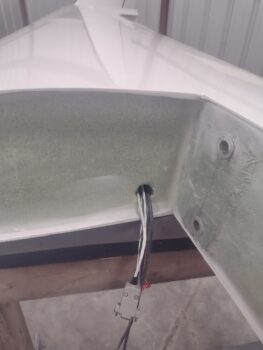
Also technically this is a 2-day post, as I spent nearly 3 hours terminating the wing light feeding wires out of the strakes into their respective 9-position D-Sub connectors.  Part of this task involved soldering ground pigtails to the shielded cables (one per light unit) and terminating those ground wires along with the others.  All told I used all 9 pins of each DB9 connector.

I’m not too worried about water or moisture getting into the DB9 connectors since I’ll be adding RTV where the wires enter the connector backshell and heat-shrinking the junction of the two mating connectors.  But during the occasional times I’ll remove the wings, I honestly didn’t want to mess with the unscrewing and screwing of those small 4-40 screws during each wing install and removal.  That was driving me towards using the much bulkier Deutsch or Molex connectors until I saw a hack for securing D-sub connectors on the VANs forum: Paul Dye and others simply use zip ties or safety wire to secure the two connector halves together.  EZ-PZ!

DAY 2:  Early this morning I scooted over to the hangar and terminated the 9 wires coming out of each wing with sockets (after soldering on the shield ground pigtails) and then terminated those into 9-position D-sub connectors as well.  I then installed the gray back shells.

I then took the day off for my wife’s birthday and spent a good half of the day at the beach watching a music festival before heading out for the evening for some food and libations.

Tomorrow I’m heading with Jess down to Wilmington for another full day of birthday festivities before getting back to work on the plane Monday.

Yes, a small break… then back to gettin’ er done!

Chapter 22 – Quick Panel Update

As I mentioned in my last post, this past weekend with the airshow and Mother’s Day made those days a wash in regard to the build.  In addition, my wife’s birthday is this coming weekend so I’ve spent the last few days installing a car stereo in her Mustang (along with other much-needed tasks) since the one in there was dead as a door nail.

I’ve been meaning to send out the GNS480 GPS unit to Chris Short, but have been so busy I haven’t gotten around to packing it up to send it out.

I then decided before I send out the GNS480 to get a quick video with it at least installed in the panel to show the panel wiring complete, with the Trio autopilot installed as well.

At which point I discovered an issue with the Trio autopilot, which I cover in this video. And much like my last video, I filmed it last night and finished editing it today.

Okay, my quick mini-update on the panel:

Pressing forward.

Chapter 22 – Critical GNS480 issue

This post covers the last 2 days in that I did all the work yesterday and then finished editing, compiling and posting the video this morning (before heading off to an all-day airshow).

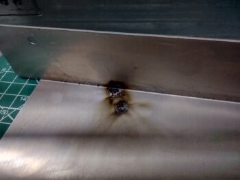
As I removed the right, narrower GNS480 unit’s case for the internal battery swap-out, I found these scorch marks on the inside….

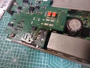
Which were a direct result of exploding capacitors that caused this damage on one of the daughter boards inside the unit.

Thankfully, as bad and nasty as it looks, it’s all mainly residue and the components, while blackened, are most likely undamaged… much like my Mom used to say about the black charred toast I’d often get for breakfast! (this info per my discussion with Chris Short, who saw these pics that I sent him).

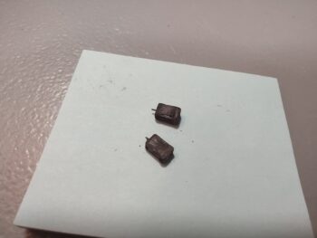
Here are the offending capacitors, which there is at least 1 or 2 more pairs of these that need to be swapped out inside this unit to ensure this doesn’t happen again (thus the unit will be shipped off to Chris Short for repair and assessment).

For size reference, here are the capacitors on a small Post-It note.

But the show must go on, right?!  So in lieu of this setback and I went ahead and finished my internal battery swap-out task.  And here is the video to prove it.  Enjoy.

I will note that for the rest of the today I’ll be at Cherry Point MCAS with my little buddy (friend’s daughter) to watch the Blue Angels do their stuff.  Tomorrow is Mother’s Day so I’ll be spending as much time with Jess as possible.

I plan to get back to the build bright and early Monday.

Chapter 22 – GNS480 tube wired

This blog post covers the past 2 days.

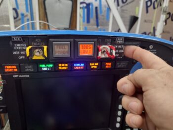
Of which, I spent multiple hours over the past couple of days slowly figuring out the issue with my Push-To-Test feature on my panel indicator lights.  One issue was I had accidentally snipped a ground wire to the PARKING BRAKE ON indicator while wrangling all the wire together.  The wire was (or appeared) intact as I just cut 3/4″ of the way through enough to cut all the wires inside, but not snip the wire in two.  I cut and respliced that wire which solved the issue on my parking brake.

But why was I popping fuses?  I checked EVERY indicator light wire for a short and found NONE.  However, I noted as I pushed the PTT button in the millisecond before I saw the lights flash on and heard the pop of the fuse, I also heard a CLICKING sound.  Like a relay.

I put in a 5 amp fuse at which point it was robust enough to not pop the fuse.  But a row of LED lights should not require that strong of a fuse.  I narrowed the clicking down to relay #11 in the nose, for the taxi light actuator.  I ascertained the issue was the separate power circuit going into the lights for testing was going back through the power wire of the taxi light relay and triggering the relay.  Not sure how, as I tried to ensure no wires were touching, but as one of the two taxi light indicator white LED lights is currently dead, and the taxi light is inop for the foreseeable future (a rebuilding of that light on the future to-do list), I simply threw a diode on the offending wire and called it a day.

I then installed a 3 amp fuse and called it a day [this issue came about AFTER my work on the taxi light circuit final wiring and pivot arm testing].  Problem solved.

I then populated the GNS480 GPS mounting tube business end with its DSub connectors and 90° antenna connectors before mounting the tube into place.

I installed the front 8x #6 CS screws (4 each side) into the internal edge of the panel using Loctite as this is the final install.

I the wrangled and secured the wires on the GNS480 mounting tube before mounting the vertical securing arm into place.

With the GNS480 mounting tube wires and antenna cables in place, I was then able to determine the correct length required for the GPS antenna RG58 cable pigtail that connects the actual 90° antenna to the GPS antenna’s RG400 cable.

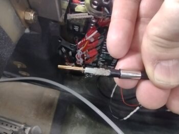
I cut the outer sheathing off as needed to then crimp on the center pin.

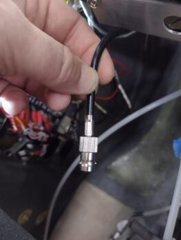
I then snapped on the BNC barrel and crimped the sleeve into place to secure it.  This is officially the last one of my antenna connector BNC connector installs on this bird! (barring any issues of course…)

I then spent well over another hour securing all the remaining stray wires on the left hand side of the Tri-paragon and avionics bay.

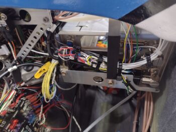
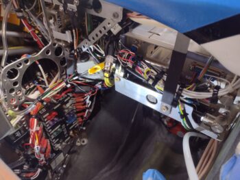
Here we have a long shot of the left side leg transit channel through the left side avionics area wiring that has been subdued… with prejudice!

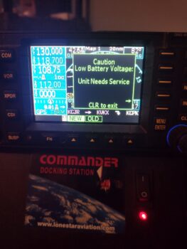
Admittedly, I spent another good hour plus trying to get my GNS480 unit to seat inside the tube.  I need to keep working to find the interference issue.  But to eliminate unnecessary removal of the GNS480 GPS from its mounting tube —before I solve the clearance issue mystery— tomorrow I plan on installing a new internal battery inside the case to avoid it dying on me with the GPS installed in the bird… due to this caution message that’s popped up a couple of times.

I know, classic problem avoidance… ha!

Moving forward.

Chapter 22 – Video cams installed

This post covers the last few days.

I used black RTV to secure the bottom “belly” video camera and aerodynamic encasing bump (a mold of the old Feather Lite composite nose puck) to the underside of the airplane.
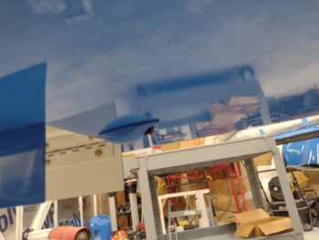
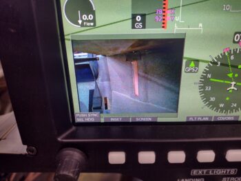
While mounting the bottom video camera, I was in real time positioning the camera and encasement bump to get the video image framed as straight as possible.  I first started off with the landing brake down to align the bottom edge of the video parallel to the bottom edge of the landing brake (pic 1).  And for left-right windage I simply used the outside of the main gear wheels to align the video image (pic 2).  It did slip just a hair to the right as it cured, but still totally acceptable.

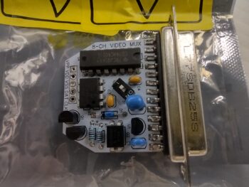
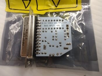
Once the video cameras were no-kidding programmed and operational, I spent a good 45 minutes finalizing the video connections with heat shrink and zip tying it all up with the video multiplexer (MUX) to secure it all.  I then mounted the MUX and bundle of wires up under the Tri-paragon’s top shelf.

After extending a couple of wires that were coming from the left sidewall and would not have clearance with the GNS-480 GPS mounting tube in place, I then spent almost an hour slowly positioning and installing the GNS-480 mounting tube into the panel, complete with a deconflicting components and rerouting wires for clearance.
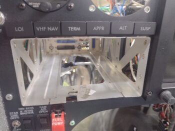
After the GPS mounting tube was in place, I also spent a few hours extending almost a half dozen wires that were not able to allow installation of GPS indicator lights, GPS radio PTT wire, etc.

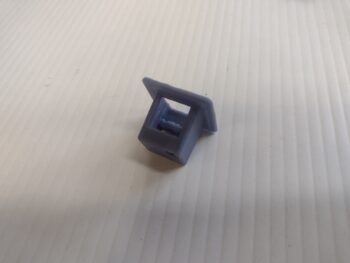
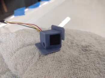
Day 3: I got busy installing the fuel site gage video cameras, which took a good bit of trial and error to get them right.  Moreover, I had one 3D printed video mounting bracket on hand from about a year ago (or more), but needed another one for the other/left camera.  Apparently I hadn’t saved my latest CAD file because I needed to spend almost an hour updating it to get it “good” like the one I had on hand.

BTW, getting it “good” means the ability to insert the video camera into its mounting bracket without damaging anything.  Which I did just that by accidently ripping off 2 of the 3 wire leads to the camera board.  These wires are VERY tiny, and it took a lot of diligence and care soldering them back onto the tiny board without screwing them up!

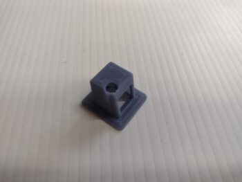
That being said, here is the #2 version of the video camera mounting bracket (the right camera’s bracket is black, and I already had it taped into position inside the strake baggage area).

After another hour of assessing angles and video quality, as well as getting the cameras tucked away as best possible as to not get damaged whilst cramming bags and stuff into the strakes, I decided to do another mod and mount the cameras in the very corners of the strake baggage area just inside the opening on each side.

This meant having a mounting flange for the underside of the top strake skin, and the inside wall of the baggage compartment (aka the original aircraft side skin).

Here the left camera is installed into its mounting bracket, and ready for install.
I mounted the left camera first, using E6000 adhesive to secure it.  I then kept checking that it wasn’t slipping or falling away from its mounted position, as I assessed the business (wiring end) of the GNS-480 tube.  This lasted for just over 30 minutes at which point I then headed off for a break . . .
My wife, Jess, went out to the beach with a girlfriend to celebrate Mother’s Day and got back earlier than expected.  She wanted to go for a scoot on the Harley, and how could I deny her that!!  So we took a few hour break, went down by the water and had a snack while watching boats and dolphins do their thing.

Upon returning home, I then installed the right camera in its original mounting bracket (although I had one printing as we were out on the bike).  With the GIB map light mounted where it is, I could not mount the right video camera up against the inside wall in the corner as I did on the left side.

If I was forward of the light than obviously the map light would be in the way…
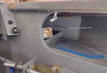
So the only other option I had was to mount the video camera outboard of the map light, and just slightly forward of it at an angle, which both hides and protects the camera a good bit, but it does affect the image quality slightly mainly due to the amount of light coming in towards the camera.  That being said, the video quality is still definitely good enough to see the fuel level… and remember, this is with all the shop lights on AND without the canopy installed.
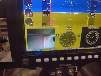
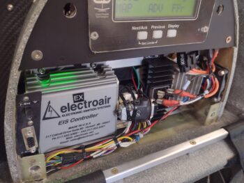
I’ll note that when I went to check the install of camera #1 earlier, after flipping on the master switch I heard fans whirring as if I had just turned on a computer.  I had not heard that sound before and it was coming from the aft of the plane.  I then noticed the green light glowing in the engine electronics bay in the GIB headrest.  Ahhh, the cooling fans have a thermostat to start the fans anytime the temp is above 82°.  I checked the shop thermometer and it was 84°… a serendipitous component check, showing they work!
Back to the GNS-480… I terminated all the GPS annunciation Korry lights and then added a dab of RTV on the terminals to keep them secure.

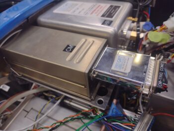
I also finished installing the COM 2 radio, which entailed getting into the Hell Hole to loosen up an Adel clamp on the antenna cable to allow me to get a few inches of slack for the antenna cable to route underneath the Trio autopilot control head when it gets installed.
Pressing forward!

Chapter 22 – Video cams online!

Ok, so after 2.5 days of troubleshooting the Video Camera System feed into the HXr EFIS, with Eric Page’s help I finally cracked the code!

How you ask?  Good question!

And admittedly I’m not quite sure.  I did attempt to roll the configuration back to exactly how it was depicted in the diagram I received with the Mux.  I’m note sure if collectively my 3 configuration changes —along with serendipitous ham-fisted trial & error button-mashing— did the trick.

But here is a bit of an overview of both the cameras and some of what I did to get the system functioning as designed.

And with that, I’m calling it a very late night.  Back to the grindstone tomorrow.