Another quick update for the past 2 days.
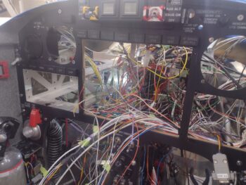
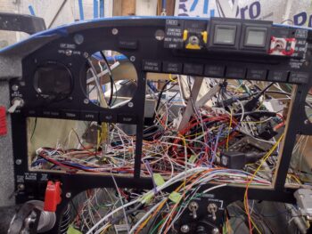
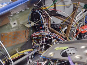
First, I’ll start off by saying that since I had knocked out most of the electrical wiring harnesses (usually in the cold winter months) over the past 10 years my thought on finishing the electrical system in situ inside the bird was going to be pretty much plug and play, with at least 70-80% of the wiring simply needing connection to other components, busses, etc. However, that number is actually inverse with all but 20-30% of wiring needing further massaging for final routing, connection and termination.
Having taken a couple of years of organic chemistry in college, I explained it to my wife as such: For any given molecule with a certain makeup of, say, 6 atoms of element X and 12 atoms of element Y, there can be a half dozen physical SHAPES of the molecule, some lending to better chemical reactions, others not as much… again, all due to the physical shape of the specific molecule.
In many ways that is very close to what is currently happening inside my aircraft. For example, coming from the front-to-aft bundle of wires were 2 ground wires that on paper, based on amp level, I had getting terminated into the G5 ground buss, which is located midpoint on the LEFT side of the Tri-Paragon.
 Now, as you’ve seen in the pics that I’ve been posting, I have A LOT of wires… as most aircraft do. So why should I run 2 wires past the G4 Ground Buss (above) to a ground buss distinctly further away? When I can simply cut them shorter and dive them right into the G4 Ground Buss and not have as many wires to contend with in open space.
The main couple of reasons NOT to would be to save time (always good) and lack of capacity on G4 (not an issue).
What it does require however is lopping off a perfectly good D-Sub pin to then crimp a FastOn connector AFTER relabeling the wire AND updating all the associated diagrams.
Yes, helps a lot with all my wires in the cleanup and management of the wiring, but it does take a bit more time to get from point A to point B. This is just one example of many how my wiring management is going, and why it’s taking a bit more time than I had initially expected.
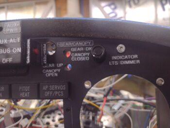
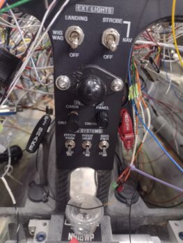
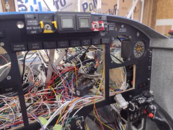
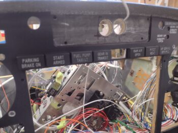
Switching gears… I got my new panel indicator lights from PCFlights in the mail today, with 2 of the 3 new lights installed (not permanently yet) in the panel: 3rd from left “FUEL PUMP” (top) and “TAXI LT” (bottom) and then a single light on the far right end, “AP SERVOS OFF/PCS” which will illuminate when I depress the AP OFF/PCS button on the control stick.
PCS is Pilot Controlled Steering that enables you to temporarily take control of the bird while it’s being flown under autopilot control then once released the control is handed back over to the autopilot/servos. The trick here is to keep the button depressed for 5 seconds or more to engage the PCS function. So yes, the light technically covers two somewhat separate functions, but they are both initiated by the physical act of pushing that single button.
[The final new light: “STARLINK” (top) and “CABIN HT” (bottom) is currently attached to Relay 21 and I was lazy in not wanting to disassemble that to mount the light… but it’s ready to install]
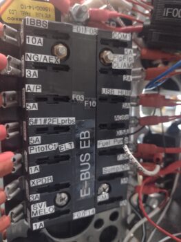
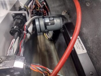
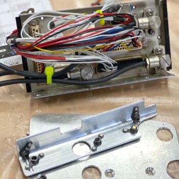
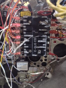
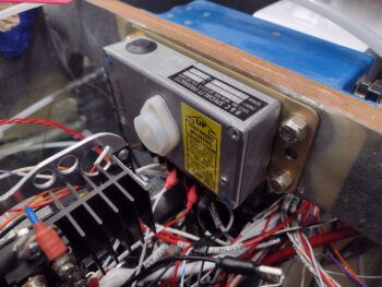
 Back to my original point above, after installing the SmartStart module and attaching its D-Sub wiring harness, I then realized that nearly half the wires need to come out the left vs right side of the Tri-Paragon. Plus I needed to solder a wire close to the connector coming from the front-to-aft wiring bundle. So off the D-Sub connector came (which is a PITA!… requires a mirror), wiring routed as required, soldered, etc. and then back on went the D-Sub connector. Note the red power wire connected to the lower right (aft) fuse tab on the E-Bus.
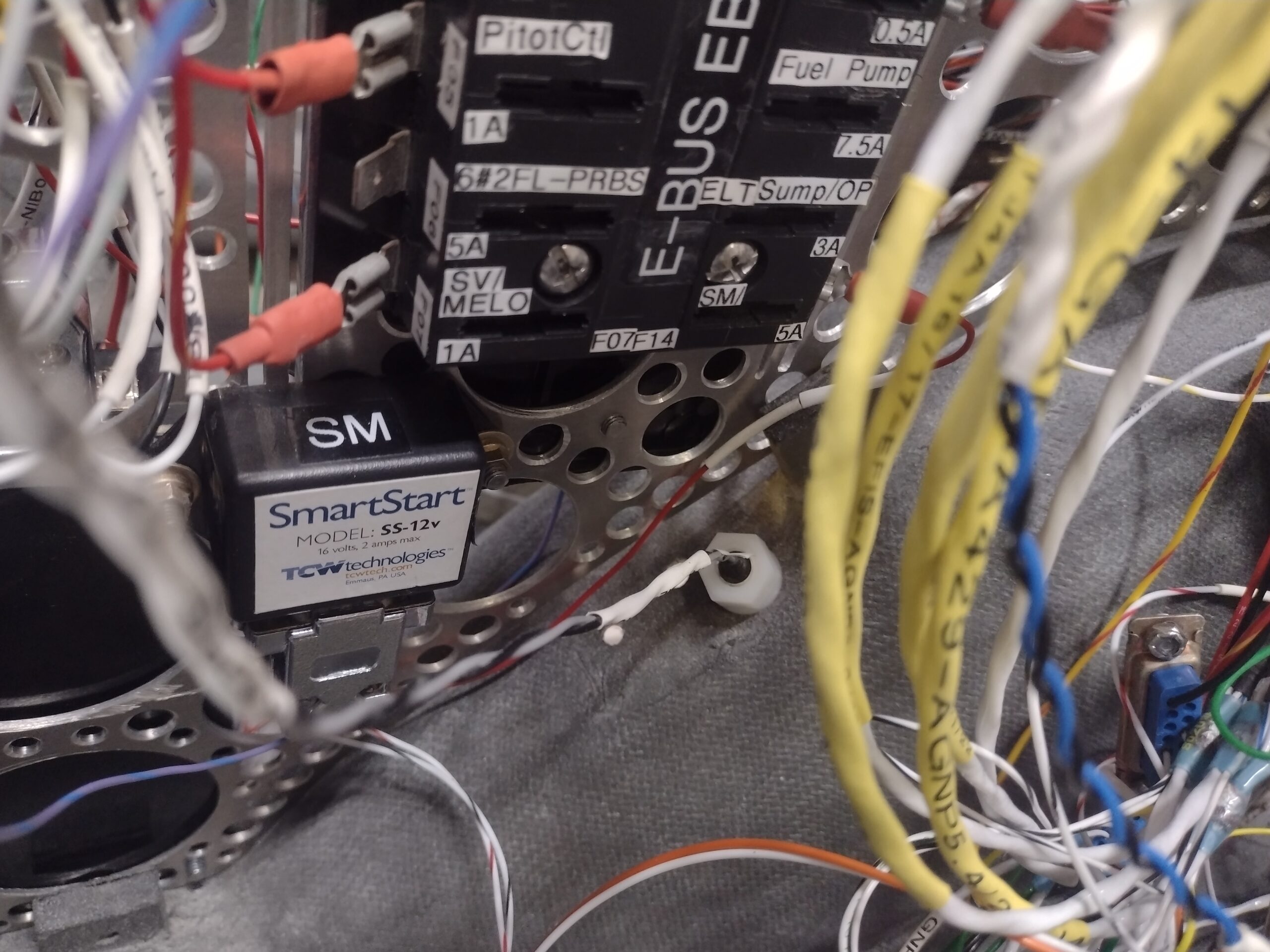 Also note the large white nylon nut to the immediate right of the SmartStart module. This is the GRT HXr OAT probe that installs into a hole from the outside-in, which was fine and happy for the many years it sat on my panel mockup. But here in the real aircraft, it required removing one wire from the AHRS D-Sub connector and cutting the black ground wire to install it from inside the nose wheel cover to the inside of the bird. Of course after it was installed it required me to then reinsert the wire into the D-Sub and solder splice the ground wire back to its other (terminated) half.
Yep… no free lunch on this electrical system endeavor!
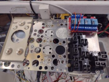
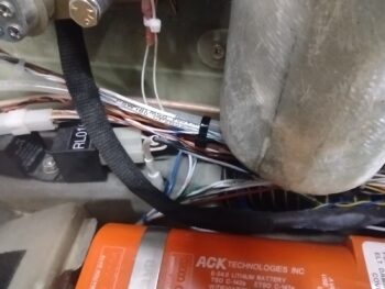
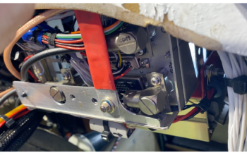
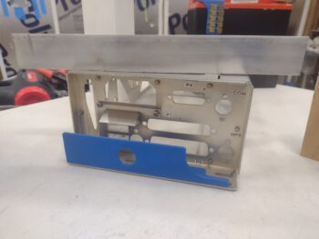
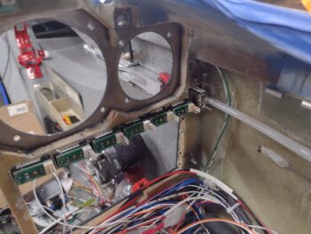
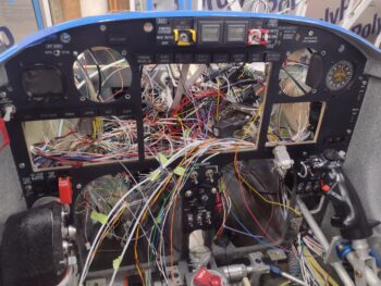
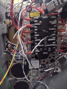
Here we have the E-Bus (again, ‘E’ is for Endurance) on the left side of the Tri-Paragon with a good many power wires attached to it, nearly all with their own story of shortening or lengthening, combining, or re-terminating with FastOn connectors (couple scenarios where I had a “piggyback” FastOn on both wires to allow double-stacking wires on the fuse tab… only one required and will fit, so I had to lop off/replace the other one with a single). I fully expect the E-Bus and most of the Main Bus to be populated over the next couple of days.
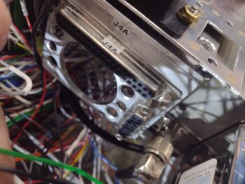
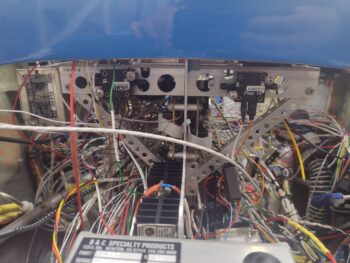
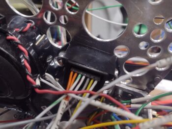
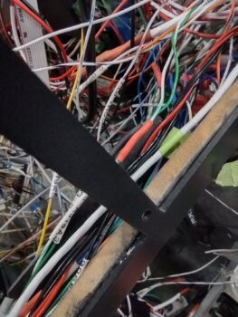
 I spent well over 3 hours today on the P5 plug wires getting that rats nest untangled and the various wires oriented, grouped and flowing nicely from that point to points yonder. This required multiple removal of wires from the P5 connector, often the same wire multiple times as the routings progressed, which again entailed using a mirror, good lighting and tons of patience to de-pin the wires in that tight corner with the P5 mounted face down.
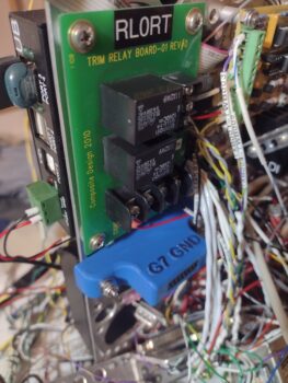
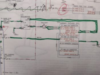
 The primary objective in my focus on untangling the P5 plug wires was first to get all the Dynon intercom wires through the bottom instrument panel bulkhead hole and ready for connection to the intercom (mid-right pilot armrest) and the headphone connections (aft right pilot armrest). Ancillary to that was freeing up Relay #9 —handles the COM1 to COM2 radio swap between GNS-480 (COM1) and the Trig TY-91 (COM2)— which is the center hub/meeting point of all the mostly shielded wires that go to each radio unit.
 Within the next 2-3 days I plan on setting aside most of a work day to focus solely on wiring up the intercom and headphone wires.
Inching forward…

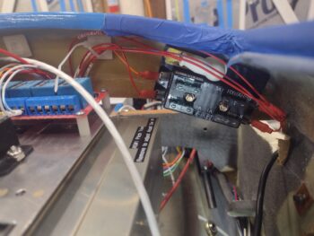
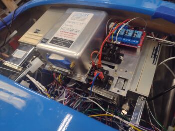
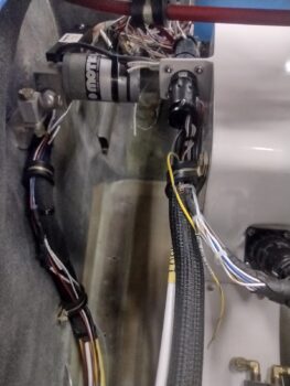
 I also routed all the wires headed up “top side” for both the X-Bus and the autopilot pitch servo auto-trim wires (white) securing them into an Adel Clamp on the right Y-support arm of the Tri-Paragon’s top shelf. Between hardware, Adel clamp sizing, wire wrangling, etc. that was a good 30-minute job in and of itself.
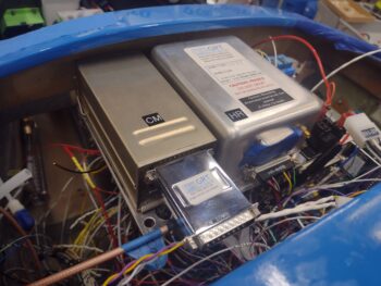
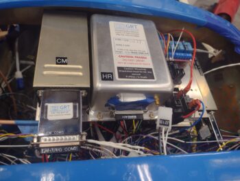
 And here we have all those wires terminated into the Trig COM2 radio, which finished off the wiring connections for all the components installed on the Tri-Paragon’s top shelf: Trig TY-91 COM2 radio, GRT AHRS, and Trig TT-22 transponder…. ok, and the relays too!
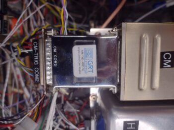 Not a huge feat for the day, but still got a good little bite knocked out.