Chapter 22/24 – Aft left armrest mount

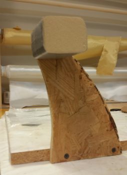
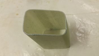
Today I started out by removing the foam form out from the middle of the left GIB armrest forward bracket assembly that I glassed last night.

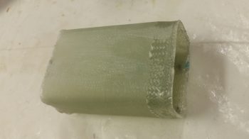
The bracket came out nicely with no glaring errors!

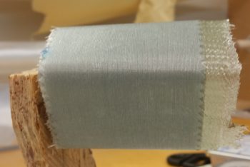
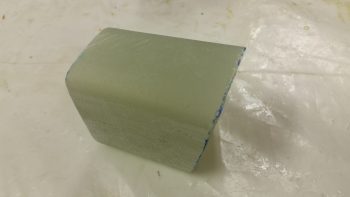
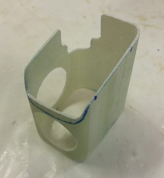
I had glassed it up a bit oversized, so I took a few minutes to measure out my bracket dimensions, mark up the bracket and then trimmed it with the Fein saw.

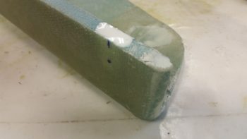
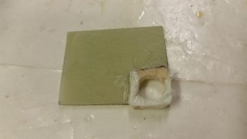
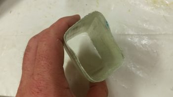
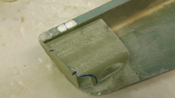
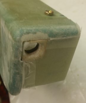
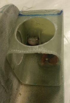
I then got to work notching the bracket in the upper inboard corner for PTT button housing clearance.  I also drilled some lightening holes: one on the inboard side and one on the bottom.

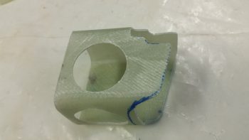
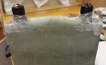
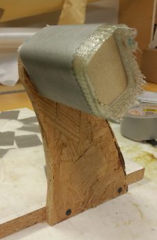
Here’s a good look at the corner PTT button housing clearance notch.

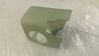
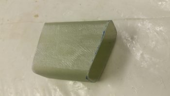
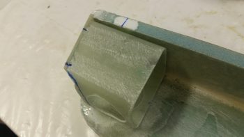
I also notched the front bottom lower edge since the face plate doesn’t come all the way down.  By moving the lower edge back a bit, there’s no way to see that the bottom bracket lip doesn’t intersect with the lower edge of the front face plate.

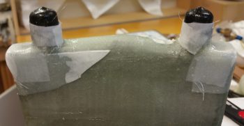
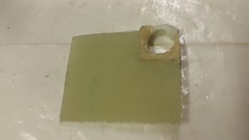
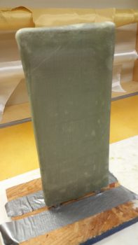
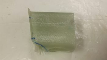
After some judicious sanding –mainly on the front angle of the armrest mounting bracket–   I taped up the inside of the armrest and then 5-min glued the mounting bracket to the front face plate.  I did this while keeping the face plate in its proper position at the front of the armrest.

After the 5-min glue cured, I immediately glassed the bracket to the face plate with 1 ply of BID in the corners for each of the interior intersecting walls, using micro fillets.

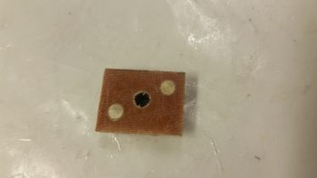
I then rounded up the left GIB mounting bracket’s nutplate assembly that I had made up a few days ago.

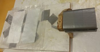
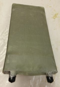
This time I taped up the edges of the face plate assembly in prep for these multi-tasked next steps.

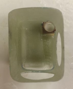
I then laid up 2 more small plies of BID inside of the bracket: 1 on each interior side of the PTT button foam & phenolic mounting pieces.

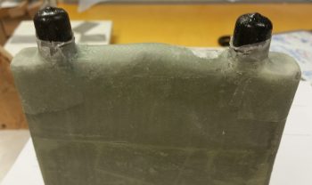
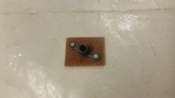
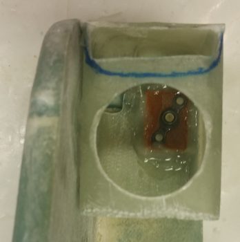
I then floxed the nutplate assembly into place on the underside of the bracket’s top plate

With the face plate taped, I also micro’d the edges of the face plate to fill in any gaps between the face plate and the armrest inside edge.

Here’s a shot of the floxed nutplate assembly in place on the underside of the bracket’s top plate.

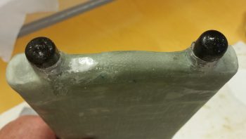
Here’s a shot of both the floxed in place nutplate assembly and the ply of BID on each side of the interior PTT button housing.

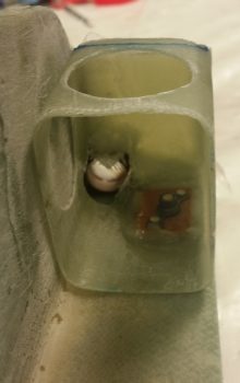
And one final shot of the ply of BID on each side of the interior PTT button housing.

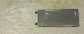
Tomorrow I’ll drill the holes in the face plate for the 2 jacks for the GIB headset.  I’ll then flox the left GIB armrest bracket to the fuselage sidewall.  All that will be left then for finishing up the mounting bracket will be the wring of the jacks and PTT button.  I also intend to work on the oil heater heat exchanger ducts as well.


Chapter 22/24 – GIB area tidbits

Today I started off by prepping the corners of my recent heat exchanger BID cover for glass.  I had actually glassed on a couple plies of BID during the initial glassing of the heat exchanger cover, but with so much finagling of the glass to get it to lay down right, the corner plies were mangled beyond use so I just pulled off the blobs of BID and chucked ’em.

Now it’s time to remedy the exposed corners immediately adjacent to the AN fittings (black caps) on the oil inlet and outlet tubes of the heat exchanger.  I knifed some dead glass away and sanded the corner areas in prep for the 2-ply BID layups.

I then laid up 2 plies of BID on each corner and peel plied the layups.

I then got to work on the left GIB armrest forward composite mounting bracket that will also house the GIB PTT button & GIB headset jacks on the front face of it (which will get attached to this bracket frame later).  I used a 2″ thick urethane foam block for the form and cut the block 3″ long.

I then sanded the foam block form into shape, radiused the corner edges for glass and taped it up with duct tape.

I then cut out 3 strips of 3″ x 8″ BID and 2 strips of UNI the same dimensions for a total of 5 plies of glass.  I then put the glass into plastic for a prepreg setup.  I also mounted the  left GIB armrest forward mounting bracket form onto a vertical stand to make laying up the glass onto it much easier.

Here’s another shot of the left GIB armrest forward mounting bracket form attached to its vertical stand.

I then laid up the 2 sets of prepregged glass so that the layup schedule was a simple BID-UNI-BID-UNI-BID pattern with the UNI plies at a 30° bias, with each UNI ply in the opposite direction.  I then of course peel plied the layup.

Yet another shot of the 5-ply glass layup for the left GIB armrest forward mounting bracket.

With the same epoxy I also whipped up some micro to pour into a hardpoint divot that I had created at the left GIB armrest forward mounting point.

By this time, the layups on the two corners of the heat exchanger had cured.  I pulled the peel ply and cleaned up the layups while they were still in that nice “green” stage.

Here’s another shot of the layups on the two corners near the AN fittings of the heat exchanger.

Tomorrow I’ll continue to work on both the heat exchanger and heating/air ducts while also working on the left GIB armrest forward composite mounting bracket.


Chapter 22/24 – PTT & Heat Exchanger

Late Friday I laid up 1 ply of BID across the front face plate of the GIB left armrest.  I pulled the BID down through the hole in the foam recessed housing for the PTT button.

Well, when I trimmed the glass off on Saturday, unfortunately a good chunk of the foam came with it.  I then needed to repair it of course.  Being in a rush for a social engagement, I quickly wrapped up the PTT button in saran wrap & tape, and then set it in what remained of the hole and weighed it down.  I then whipped up some flocro and –using the taped-up PTT button as a form– rebuilt the recessed housing “frame” around the PTT button.

Here’s a shot of the left GIB armrest’s front face plate, with the repaired PTT button foam recessed housing.

I haven’t sanded down the repaired PTT button foam recessed housing to its final shape yet, but will get to it after the July 4th holiday festivities are over.  Still, here’s the aft side of the left GIB armrest’s face plate.

Today I focused on glassing the heat exchanger.  With help from my lovely assistant (Stacey is visiting from North Carolina and helped with both the prep and the glassing of the heat exchanger… and I have to say, it was great having an extra pair of hands on this somewhat challenging layup!  Thanks Stacey!) I taped on two 1/4″ thick rounded wooden runners on top and bottom (that I cut on the table saw Saturday), made some flat cardboard end caps for the U-shaped tubing on each end to make the whole cover a more even rectangular shape, and then wrapped it all in plastic.  I then taped it all up, first with duct tape, then with clear packing tape.

We then cut out BID to make up a 2-ply prepreg setup for each end.

We then wet out the prepregged BID and laid up the end pieces.  Then over the end pieces, we wrapped and wet out 3 individual plies of BID, one at a time around the entire middle area of the heat exchanger.  The corners did give us a hassle, so on the non-AN fitting end I used a bit of micro in each corner and laid up some “corner cap” pieces of BID.  I left the corners on the AN fitting side alone for now and will glass them during round 2 of enveloping the heat exchanger in glass.  After laying up all the glass, we peel plied it all and let it cure as we went out to meet some other friends for dinner.

Above and below are actually shots of the glassed heat exchanger after I pulled the peel ply.

Tomorrow we’ll be celebrating July 4th, so no building is planned.  I do plan on getting a fair amount knocked out starting back full steam on Thursday.