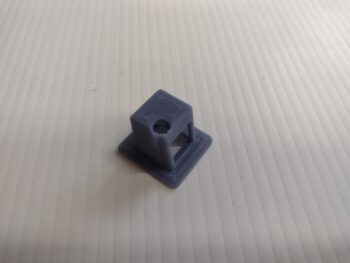
I failed to show in last night’s post that I had pulled out the safety block on the nose hatch door latch pull handle… since messing around with it I realized that the RTV was not holding it in place as I had expected it to.
 Now, I went back into my Fusion 360 CAD to find the model, tweak it with 2x #4-sized screw holes and reprint it the new center block to install it with screws. However, I simply could not find the CAD file for this safety block. My guess is that I didn’t save it, and with the constant uncommanded reboots of my laptop with MicroSoft putting all the censo… uh, “security” patches on it, I lost it somewhere along the line.
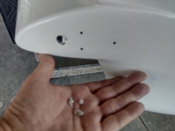
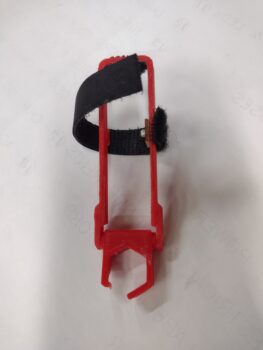
So I simply drilled the holes into the current center block.
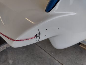
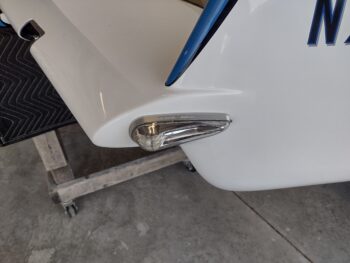
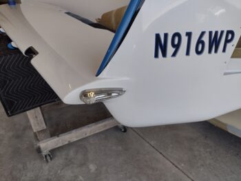
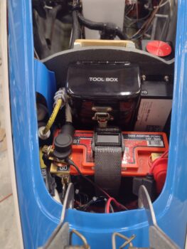
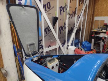
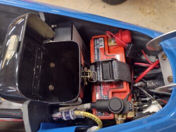
Then after drilling some pilot holes into the interfacing flange, I simply filled the center block as best I could with flox, slathered up the mating surfaces with flox, and then screwed the screws into the flange (pic 1). This morning I flipped the block down over the handle and tested it out (pic 2). All good. Task complete.
In other news . . .
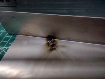
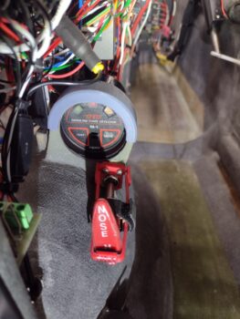
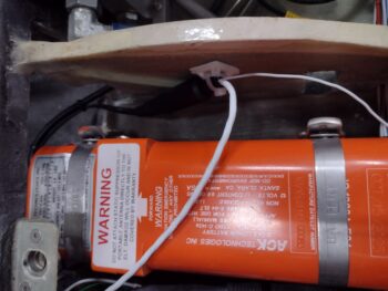
My WxWorx Sirius XM weather receiver manual was a casualty of Hurricane Dorian and is fused together in what is now a thick piece of cardboard that resembles a users manual. Their website didn’t have any downloads, so I emailed them and had one sent to me by the next day.
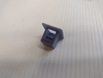
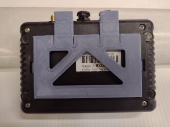
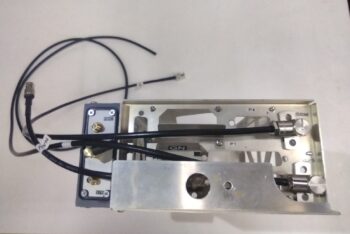
In the manual I noted a picture of the WxWorx receiver in a mounting plate, as it described how to first install the plate and then secure the receiver in it. Hmmm? I don’t have said plate and thus looked for such a plate on eBay and elsewhere online, only to find a pic of it… as you can see here.
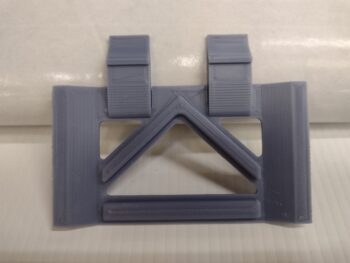
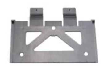 So I took the pic and converted it into a CAD model and over the last few days I’ve been tweaking and dialing in the design of my own WxWorx receiver mounting plate. This is version #4 I believe, and it actually works quite well.
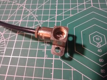
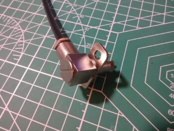
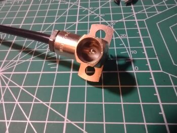
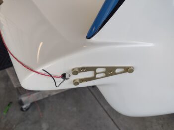
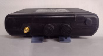
On the receiver’s underside there are two small indentions that a tang on each of the extended arms snap into. As you can see along the side there are interfacing grooves that the mount slides into. This serves to make a very solid fit and locks in the WxWorx receiver quite nicely.
To remove the WxWorx receiver from the mounting plate you simply press down on the two tabs while lifting and pulling the unit slightly to disengage the tangs from the indentions and it pops right off. EZ-PZ!
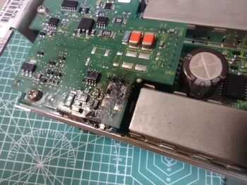
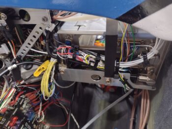
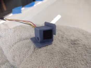
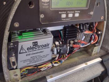
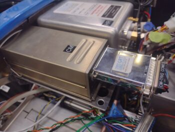
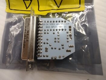
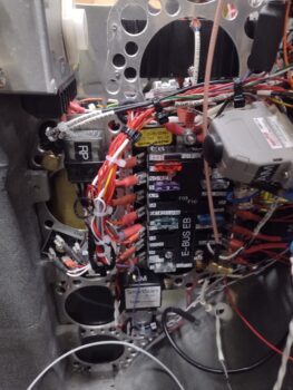
 I spent nearly 2 hours today finishing up the final wiring of the video cameras and the video camera MUX unit. I then mounted and secured the video camera leads and the MUX unit to the underside of the Tri-paragon shelf.
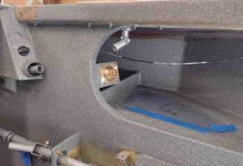
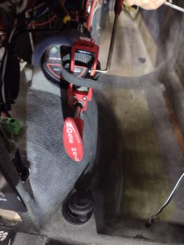
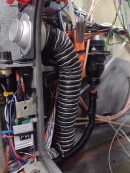
I also tweaked the final configuration for the static tubing crossing over from one sidewall to the other, meeting in the middle (in front of the HXr).
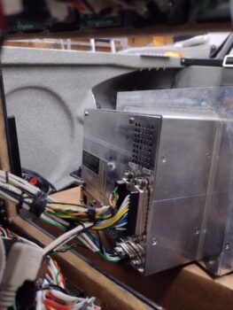
With all my final prerequisite tasks out of the way, I then got busy with the final install of the GRT HXr EFIS… here it is on its temporary base that allows me to get the wiring harnesses to the HXr without too much hassle.
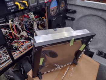 And here are the 3 wiring harnesses’ D-Sub connectors screwed into place on the backside of the HXr EFIS. The only other connections besides these 3 D-Subs are 2 USB connectors (the short one to the USB hub proved to be quite a challenge and took a good while to finally get installed on both ends).
 I was on the phone with my daughter during a good bit of this install process, so not shown is the feeler gauges that I slipped under each of the top row indicator lights to allow me to push them up slightly in a wedging fashion as I slowly threaded in each of the EFIS corner screws. Three of those feeler gauges took quite a bit of force to yank free of the grip they had between indicator light bottom and HXr top edges… but brute strength won out. Ha!
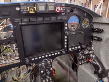 And Voila! The GRT HXr EFIS is now officially installed.
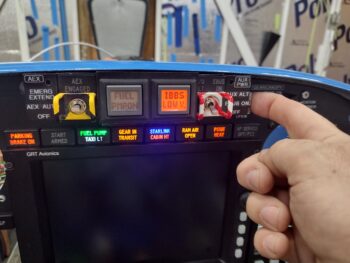
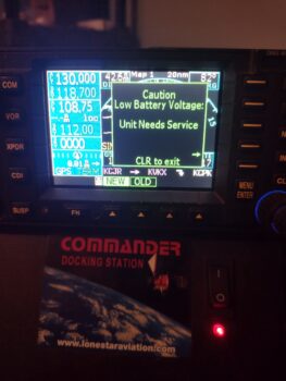
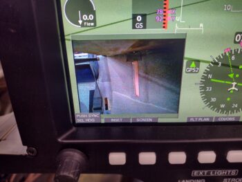
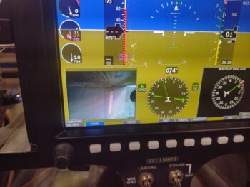
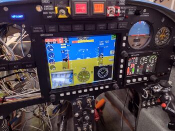
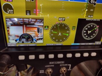
I then fired up the panel to test my EFIS install in general, but specifically to check the video camera system. I’m super happy that my wiring to the fuel site gage video cameras are all good, as you can see the left one in the lower left inset screen of the HXr EFIS (camera is pointed at the ceiling).
 However, my happiness that the video cameras themselves were operational and functioning nicely was dampened a bit with an issue I’m having with the Video Camera MUX cycling through the respective video cameras as it was designed to do… as in it is not doing so at this time.
Each camera feed I’m showing in these pics is all connected to the exact same camera input on the MUX.
Something is clearly not right, but it may be something as simple as it’s currently programmed to only receive one camera input. I fired off an email to the primary developer of this unit, my ‘Electronics Guardian Angel‘ Eric Page, and will await his answer to see if he has any input (I have a list of possible fix actions that I will try in the meantime).
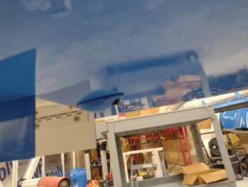
That all being said, here is the right fuel site gage video camera putting out a nice, spiffy video feed as well. I am SO GLAD that the wiring for these fuel site gage cameras are operational and I do not have to get up into the bowels of the strake baggage compartments to fix them… bullet dodged! Whew.
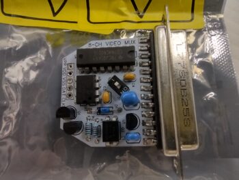
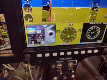 And to reiterate again: these video feed shots are all on the same single input (out of 4 hardwired on the unit).
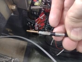
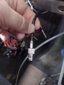
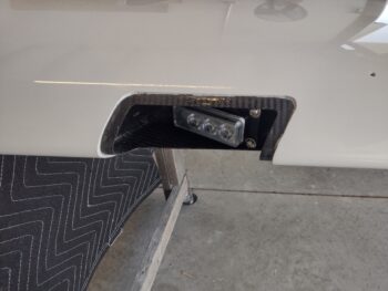
This feed is the 5V aft-looking video camera mounted in the top of the pilot’s headrest (which is connected via Eric Page’s spiffy 12v-to5v “buck converter” that I just recently received from him). As a point of note: the Video Camera MUX can handle up to 8 video cameras, but Eric knew I was only utilizing 4 cameras… so to minimize the footprint he only added 4 camera video connectors.
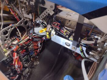
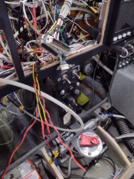
 The #4 video camera is also aft looking, only on the bottom of the bird… just behind the front nose gear wheel well (straight below the instrument panel). I didn’t test this camera because it’s connector is buried in the thatch of wires in the middle of the panel, under where the HXr is now situated. This junction was the meeting point for nearly ALL wires coming from the right, left, forward, aft, up and down sides of the bird… and yes, it’s super busy, crowded and not as streamlined as I would like it. But it is what is —wrangled, routed and secured to an acceptable level (IMO).
I will also note that I had a gremlin pop up in the top row indicator lights. I believe I’ve isolated it down to one my “double-stack” 2-row lights and will investigate that tomorrow.
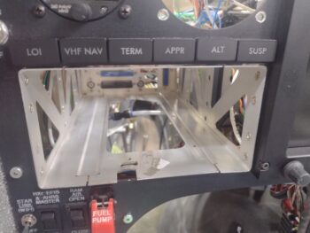
In addition, the mounting location of the Video Camera MUX is such that it needs to be mounted in place BEFORE I can mount the GNS-480 mounting tube, so resolving the MUX camera cycling issue is a priority in getting this panel installation completed.
But all that being said, STILL pressing forward!