Chapter 23 – Left pipe redo…

As I mentioned yesterday, I realized that I couldn’t proceed any further on the aft side (“outriggers”) baffle seals install without first getting the outboard left exhaust pipe in its final configuration.  To do that I need a very slight bend or curve near the midpoint around the base of the inboard exhaust pipe to then allow the remaining aft section of the outboard pipe to align and nestle in more closely to the inboard pipe.

Here I’ve marked the removed outboard exhaust pipe (cylinder #3) for cutting into two parts, as well as the scrap curved section that will be getting spliced into the middle section of the current pipe.

I had meant to get a pic of all the component parts after I cut them, but alas I got too wrapped up with getting this thing knocked out… thus it went back on the engine post haste.

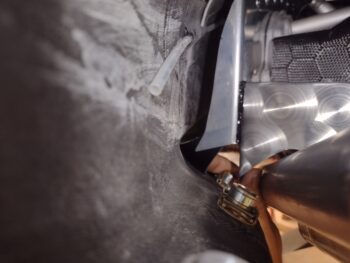
You can see by the two respective alignment marks that the very slightly curved middle insert is taped into place.

A few pictures here are only the highlights of the well over 3 hours it took to cut and very carefully dial in the left outboard pipe pieces for both windage and elevation in respect to its own position within the cowlings, and in relation to the inboard left exhaust pipe.  That being said, the end result came out pert near exactly what I wanted/needed: the left outboard exhaust pipe —at the proper elevation— aligned parallel with the left inboard exhaust pipe (note the inboard pipe aligned with its bottom cowl mark).

Of course now I’ll need to get with James for him to work his magic welding kung-fu and get this outboard left exhaust pipe final configuration locked in.

As a comparison, this is what this pair of pipes looked like before my corrective alignment “surgery.”

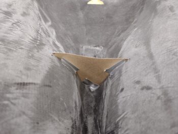
Also, here is the bottom cowling mini-aft baffle bulkhead with its height trimmed…

And the resulting gap between the bottom cowl mini-aft baffle bulkhead and the bottom edge of the baffle at 0.15″, offset just enough to allow for any clearance required.

With the outboard left exhaust pipe repositioned, I could then focus on the left aft corner baffling.  After taking a myriad of measurements and looking at the situation from just about every angle possible, I developed my plan to allow both the baffling to get installed in this corner, as well as a Melvill-style exhaust-securing bracket that will both close up/seal the baffle gaps around the exhaust pipes and secure them into position.

The initial step to installing the exhaust pipe bracket is to add a piece of aluminum angle (blue in pic) into the lower left corner to mount a K1000-3 platenut that will be one of four securing the exhaust pipe bracket.  I’ll further note that my intention is to get this aft left corner completely knocked out, regarding both baffle installs and exhaust pipe bracket situated, before moving onto the right side.

Moreover, as I was putting the cowlings on and off, I discovered an issue with the top cowl’s right side baffle rib clearance with the engine baffles that caused the seal to get all wonky.  I finally figured out the issue after some investigation and I’ll be trimming down the depth of that baffle rib as well.

Pressing forward…

Chapter 23 – Dialing in baffle seals, etc.

I started out this morning with lots of assessing and planning of the aft side baffle seals.  However, I quickly discovered that I will need to work the exhaust pipes’ brackets before finalizing the configuration of the outboard baffle seals since they all need to integrate together.

Since I needed to assess the exhaust pipes configuration, I then mounted the bottom cowling.  Which also confirmed that the bottom cowling can be mounted with the top cowling in place… the order doesn’t matter.

With the bottom cowling on, I took the opportunity to mark the aft bottom baffle bulkhead for trimming (green tape).

Then, using my alignment mark on the aft edge of the bottom cowling, I set and taped the left inboard exhaust pipe into its position (see last pic below).

After a bit more assessing of the upcoming outboard baffle seals and the exhaust pipe positions, I then pulled the bottom cowling and trimmed the aft baffle bulkhead with my “Fein” saw.

I also pulled the top cowling off, marked the top cowling’s front cross reinforcement and baffle rib before trimming it with the Fein saw as well.

I cleaned up and dialed in the top baffle seals by trimming the aft seal edge on each side as well as punching a relief hole on the inboard side of each slit I made (to flatten out the seals as they’re positioned inside the top cowling).

I then removed the outboard left exhaust pipe and prepped it for cutting it in half (take 2) and resetting it so that it curves in closer and aligns more with the left inboard exhaust pipe.

Chapter 23 – Top side baffle seals

Again, this post covers the last 2 days.  I started by trimming and installing the left side top baffle seals and reinforcement strips.

I then focused on installing the right front side baffle reinforcement strip, first by drilling out the rivet holes (pic #1) and then creating the oval socket extension hole for installing/removing the spark plug in cylinder #4 (pic #2).

I then configured and temp installed the right front baffle seal.

And then set and drilled out the rivet holes on the right aft side baffle reinforcement strip.

After knocking out all the prerequisite prep work, including trimming the top edges of the right side baffle seals, I then gooped up the top baffle seals and riveted them in place with the reinforcement strips.

Here we have the left and right side top baffle seals and reinforcement strips installed.

And another shot of the installed front, left and right side top baffle seals.

After a good bit of getting the baffle seals flipped the correct way, situated and compressed down in proper fashion I was able to get the top cowling fastened into place.

Again, the initial placement of the top cowling with the just-installed baffle seals took a good bit of machinations, but I finally got ‘er on.

My first task was to assess the top cowling front cross baffle and reinforcement rib to see how well it cleared the aluminum baffle wall.  As I could tell by the rivet faces, I’ll be trimming just a bit more of it off so that it clears at least the baffle seal rivets.

After shoving my work light into the engine compartment to light everything up, I then used my trusty inspection mirror to assess the front wall baffle seal.  At every angle I could see it all looked good and firmly pressed up against the inside of the top cowling.

With the pronounced curve of the top cowling on each side —and thus the side baffle walls and seals— I wasn’t surprised to find some bunching up of the side baffle seals.

Here we have the forward side right baffle seal bunched up a good bit.  Near the corner was pretty much corrected by me just smoothing out the baffle, although I will need to trim it a little.

The major wrinkle just above the cylinder rocker cover was remedied by me reaching up with a razor knife and creating a slit until it flattened out.  With pressure on the baffle seal, it wasn’t a perfectly straight cut, but I wanted to do it in situ as to assess the results real time.  I’ll clean up the slit edges when I remove the top cowling.

The left side also had some bunching up both fore (pic #1) and aft (pic #2).

Again, I used a razor knife to cut the slits at the wrinkled seal spots to flatten them out.  And again, not perfect slit edges… but I’ll clean them up after I remove the top cowling.

I’ll reiterate that besides some fairly minor corrective slicing of the baffle seals in a few tactical places, overall I’m very happy with how they’re situated and sealing against the inside of the top cowling.

I called it an early evening to have dinner with Jess.  But before I left the shop, and to help the baffle seals nestle in and conform to the top cowling’s contours, I placed a heated blanket on top of the cowling with a couple of heat lamps shining up from below.  I don’t know how much of an impact this will actually have, since this heat is no way comparable to the heat that the engine will give off while operating, but I figured what the heck… it can’t hurt anything.

Tomorrow I’ll press forward with the lower side and bottom aft baffle seal installs.

Chapter 23 – Front baffle top seals

This post covers both today and yesterday’s efforts on getting the top baffle seals installed.

Yesterday:

I started by placing the reinforcement strips along the front baffle wall, determining the spacing of the rivets (most are 1.5″) and then drilling out the rivet holes.  Once the aluminum baffle wall and reinforcement strips were drilled, I then added in the baffle seal, positioned and marked it, and then punched the holes out with a leather punch.

Here we have the front baffle wall left side reinforcement strip secured for rivet hole drilling.

Again, once the rivet holes were drilled through the metal parts, I would fit, trim and add in the top seal segments.

Once the top seals were in place, I trimmed the top edges to somewhat match the curvature of the metal baffle wall edge.  You can see that the just-added right side baffle seal has not been trimmed to shape.

Today:

Here we have the front baffle wall top seals installed, with a thin strip of RTV goop applied before the respective segments were riveted into place.

Here are some shots of the “backside” (technically front side) of the just-installed baffle seals.  I’ll note that I’m using “Cowl Saver”™ baffle seals, which claims 10x less friction with the top cowling to save the baffle seals over the long haul.

With the wider diameter head rivets that were supplied in the VANs baffle kit, using my hand riveter was resulting in about a 50% misfire rate when I used it on the lower aft baffle install.  I’ve had this cheaper Harbor Freight pneumatic riveter sitting new & unused in its box for a very long time now, so I broke it out to test it for this task.

After adding WAY too much hydraulic fluid into the reservoir (the instructions are woefully lacking on this key piece of info… as I found out watching a few YouTube videos on this thing!) and making a mess, I finally got it dialed in.  The max rated pressure for this tool is 90 PSI, and I found that 55-65 PSI is the best for setting these rivets.  However, I also found that any added material, as in the an extra baffle plate where they overlap at the engine centerline, it needs the max 90 PSI to prevent a misfire. But I’ll say overall it’s worked a treat.

I then started working on the left side baffle seals, with the main time-consuming task being drilling out the oval 1/2″ wide hole in the forward segment for the spark plug tool access hole.

Another shot of the left side baffle seals current install.

Although not baffle related at all, I figured I would add in this neat little hack of making up a template to fit the prop spinner around the prop (coming up soon!).  It was a canardian posting it on FB in prep for Oshkosh.

I knocked off work early evening to head down to Swansboro with Jess and crew to watch fireworks for an early Independence Day celebration.  Tomorrow too will be a very short work day (if any build work at all) as I have an afternoon party and then will be heading to fellow canardian Guy Williams house for food and fireworks.

Chapter 23 – Baffle seal strips made

Today was all about finishing the cutting and trimming of the baffle seal edge securing and reinforcement strips.

Again, the band saw made fairly quick work of cutting the scrap 0.032″ thick 2024 aluminum baffling leftover from the VANs baffle kit.  First up was cutting the top edge of the front left baffle edge strip.

Once I had the top edge then I could determine the bottom edge, which had some curves and dips to allow for the spark plug access hole.

I then trimmed off the bottom edge of the front left side baffle seal strip and got about to dialing it in on the actual baffle side wall.

After another 10 minutes of fine-tuning it, I had it ready to go.

I then spent a good hour underneath the engine gooping up all the gaps I could find with black hi-temp RTV.  I still have a bit more to do, but I’m slowly getting it all sealed up.  I also spent a good bit of time gooping up the baffling gaps around the starter and the alternator.

I then spent another good hour plus creating the bottom aft baffle skirt edge seal strips and getting those fitted into place.  I have them pinned here on the external side of the baffling just so that they’re visible, whereas obviously they’ll be mounted on the inside of the baffling to reinforce and secure the baffle seal material.

With all the baffle edge seal strips held in place with clothesline pins, I figured it made for a good photo op and I grabbed a shot.

I did spent a some time cutting out some baffle seal material, but no shots of those yet.  Tomorrow I plan on getting a good bit of the perimeter edge baffle seals installed.

Pressing forward!

Chapter 23 – Baffle Seal Strips

I started off today by cleaning up the aft side of the bottom cowling baffle mini-bulkhead and prepping the front side for the final layup.

I started with an inset ply of Lantor Soric to provide a little thickness and stiffness to the bulkhead, since this is also a stiffener for the bottom cowling.  I will be adding a short connected “wing” to each side, about 1/2″ high to finish off the bottom cowl stiffener on the aft side.

I then laid up the last single ply of carbon fiber, peel plied the edges that intersect the cowling and then along the top.

I cut the cardboard form and used the tape side against the top peel plied edge and clamped it into place with 2 larger clamps.  I then used clothesline pins to pinch the top seam together so that there was no resulting gap between the aft side and front side plies of CF.

With the left over epoxy I laid up a couple plies of CF on the aft left vertical side of the top cowl where there is a very slight depression (pic #1).  This should even it out straight so I’m not reliant on thicker micro to fill in the dip.

I also added a bit of flox to micro and filled in the errant first Static hole drilled on the right side nose (pic #2).  It may need a minor bit more when I finish micro-finishing the nose, but the major fill is complete.

I then spent a number of hours marking up and then using the band saw to cut out the baffle seals edge securing strips.  I also employed the Dremel tool a good bit to get these things shaped as well.

Here we have the right side and right front baffle seal edge securing strips set in place.

Another shot of the right side baffle seal edge securing strips set in place.

I was also able to complete the front side baffle seals edge securing strips.

And almost got the left side completed as well.  It was quite late at this point and those front side baffle seal edge securing strips are the most detailed of them all.  I kicked that can until tomorrow since there is a lot of cutting to do on this sucker.

With the front side layup on the bottom cowl baffle mini-bulkhead was about 80-90% cured, I pulled the edge peel ply before removing the clamps and cardboard form.

About an hour later I pulled the final piece of peel ply before razor trimming and sanding the edge.  Voila!  Bottom cowl baffle mini-bulkhead complete.

I then pulled the peel ply and cleaned up the layup on the aft left side of the top cowling as well.  Another minor yet important task off the to-do list!

Tomorrow I plan on knocking out the last topside (left) baffle seal edge securing strip before making up the ones for the lower baffle skirt.  At that point I’ll be ready to start installing the baffle seals, which I intend to get a fair amount, if not all of them, installed.

Chapter 23 – Cowl baffle bulkhead

I got a late start today with a number of distractions before finally getting into the shop.

I transferred the thin cardboard bottom cowling aft bulkhead template to thicker cardboard.  I then dialed that in to fit the lower cowling.

Once fit into place, I then covered the cardboard form with duct tape as mold release.

I whipped up some epoxy to wet out and set peel ply onto the taped form.

I then laid up 2 plies of carbon fiber and peel plied the edges where they intersected the cowling.

Then, while setting the lower cowling into place on the plane, the lower baffle plate snagged the layup and distorted it a bit on the left side.  After messing with it for a minute, I realized I was about to make it much worse since I would lose a good number of the carbon fiber strands in that corner in my attempt to set it back right… so I called no joy and simply straightened out the fibers as best possible.  After all, the strength will be there, and it is in the lower engine area, it will simply be more of a cosmetic issue.  I’ll assess later if need be, and left it to cure.

I then turned my sights onto my “new” band saw —that my welder buddy James gave me— to get it up and running.  I spent about 45 minutes resetting the motor pully and dialing in the saw.

With the saw up and running, I then started trimming a number of 0.032″ 2024 scrap pieces from the VANs baffle kit to start making baffle seal edge securing strips.

The band saw worked a treat as I started cutting a number of these baffle seal edge securing strips.  Over the next day or so I’ll finish making these up to allow me to secure the top baffle seals to the aluminum baffle walls.

Tomorrow I’ll layup the front side of the bottom cowling baffle bulkhead and continue cutting out these baffle seal edge securing strips.  My goal is to have the baffles finished within the next few days.

Chapter 3 – UNI, BID… and next build?!

I left out of the house today at around 5:30 am on my approximately 6.5-hour trek to the Asheville, NC area to pick up a Cozy III fuselage tub and rolls of UNI, BID and Ceconite from Forest, who was just wanting it all to go to a good Canardian home… or at a least a Canardian that tries really hard!  haha!

The builder was the late Wayne Martin out of South Carolina, who was Forest’s father-in-law.  Apparently Wayne traveled quite a bit for his job (I can relate!) and ended up in Thailand for many years, thwarting his efforts of finishing his Cozy III build.

Although the build plans are no longer with the project (I have a PDF copy), Forest did give me a manila folder with some info docs on the Cozy III, a Cozy III (just “Cozy” at the time) POH, and the original contract from August 1986 citing that this is serial number 302.  Official pedigree even… that’s pretty cool —all occurring as I was about a half year into my 29 year Air Force career, having just graduated the Naval School of Explosive Ordnance Disposal (NAVSCOLEOD) and heading off to RAF Upper Heyford, UK.  Crazy how life plays out.

Admittedly, my primary incentive for making this trip was the copious amount of fiberglass that Forest was including with the Cozy III project.  EZ-ily enough to do one canard airplane, probably over two of them in my estimation.  There were 2 very large rolls of UNI, a medium roll of UNI, and a large roll of BID all included.  Oh, and a longer, bigger roll of what Forest told me was Ceconite (top of pic) … for covering rag wing airplanes.

It took us about 10 minutes to get situated and get the fuselage tub loaded into the truck, and another 10 minutes of loading the glass in the back cab of my truck and tying everything down (that’s Forest in the background).

There were clouds in the sky and I of course didn’t want the fiberglass in the truck bed, exposed to the elements, so into the cab it went.

I thanked and said goodbye to Forest, grabbed some lunch in Hendersonville, and then started my trek back home.  Well, to my hangar actually.  Due to a wreck in Raleigh, where I sat (trapped) virtually dead still on the Interstate for 45 minutes, I didn’t arrive the hangar until after 10 pm.  But I got everything unloaded there without event and then had a very late-night bite to eat with Jess at a sports bar in downtown Morehead City.

Back to the Long-EZ build!

Chapter 23 – Just Gooping Around

I spent a good bit of time today cleaning up the seams and adding more goop (hi-temp RTV) to a good number of holes or gaps in the engine baffling.  I added more to the outboard seams on the aft baffles, and if you look closely enough you can see a dot of RTV on each sidewall where the 2 side panels meet.

I then focused on the front top center seam between the engine and the baffle segments.  Pic #1 shows the aft side whereas pic #2 shows the front side of this junction.

On the front left I had a couple of open holes at the corner seam where I added dollops of goop to fill in.

There were some openings that required coming from underneath and some down in the remote inner corners, which were hard to get to and harder to get any pics of… and some will simply have to wait until the engine is off to get better access to.

Overall though the gap fill is nearly complete, and I’ll be moving on in my baffling efforts.

One such task is the aft bulkhead in the bottom cowling that will actually be part of the baffling system.

I first made up a rough cardboard template…

And then mounted the bottom cowling.  You can see what I’m up to here, where the baffle seals from the aluminum baffle skirt side (upper) will seal against the bottom cowl bulkhead.

It was getting late, so I headed back into the house when I was greeted by this giant moth.  Pretty cool looking!

Tomorrow I’m heading to the Ashville, NC area for a “quick” (all day) turn and burn to pick up a Cozy III fuselage and a bunch of UNI and BID that a very nice gentleman, Forest, is giving away to a canardian that will put it all to good use.  His father-in-law started the Cozy III build around 1986, but traveled the world in his job so unfortunately never got to see it completed.

Chapter 23 – Final Alternator Bolt

I didn’t get nearly the shop work I was looking to get accomplished knocked out as planned, but I got a few other key things finished.

I started out this morning by pulling the front pair of clecos on the aft right outboard baffle wall and replacing those with rivets.  I’m leaving the very aft cleco in place since I’ll use that hole for mounting the baffle seal reinforcement strip.

Then I did the same thing on the left side.  Since the aft baffle shelf is narrower, I only have one rivet on this side.

Jess is starting back bartending again 2-3 times a week (for both EZ money and knowing that she’s going to be a “build widow” for the next few months!) and tonight she was going to work… so I ran over to Beaufort to meet her for lunch on the waterfront since I wouldn’t see much of her today.  An awesome view of the water that never gets old for me.

We then ran to the hangar for a bit and she helped me unpack and mount an end locker to my roll around tool cart.

Upon returning back home my Aircraft Spruce order had been delivered, of which contained a couple different lengths of 3/8″ bolts to replace the too-long pivot bolt on the B&C alternator.  This bolt also secures the cross link brace between the alternator and the starter.

Looking at the B&C L40 Alternator install manual I didn’t see any reference or diagram showing which direction this bolt was installed (or if it matters?) nor did I have any torque spec for the bolt securing the cross link brace to starter.  So I gave B&C a call.

B&C answered my questions, stating that they prefer the pivot bolt head to be on the same side as the alternator pulley.  TJ also stated the cross link brace isn’t required if the alternator is boss mounted (yeah, tell that to the mob at Rough River!!) and B&C didn’t have a torque spec for that bolt.  I told him that A) I bought the cross link brace and have it in hand, B) I have a big hole in the baffling where it was mounting into, and C) note “mob” reference above.  And no one is knocking this community off of our old wives’ tales!  He copied what I was saying and suggested I use Lycoming’s torque specs for a 5/16″ bolt (17 Ft-lbs).

I’ll note that this task would have been a nothing-burger if I had done it BEFORE tensioning the alternator belt.  Moreover, after measuring everything out, I determined that I could use the shorter (less weight) of my new bolts, the AN6-41A, but after install it turned out to be just a hair too short.  Swapping back out to the AN6-42A would have made for a good comedy short video, if in fact it were truly a short enough video!

Let’s just say it took WAY longer than it should have to swap this bolt out and get it installed, mainly due to alternator to boss alignment, but also the fiddly washers on the aft side… but as is always the case on these builds, perseverance paid off.

I then received a call from my good friend Greg, who was there at the very beginning when I decided to build this Long-EZ.  Before I started building I made up a wood mockup of the fuselage to determine if the stock cockpit width would be ok, and while I was out he actually climbed into the back seat of the mockup… and got stuck in there since there was no real strength to the mockup to support him climbing back out.  He essentially had to roll over sideways like a turtle to egress.  It made for a good story.

Before I headed back out to the shop I saw a note on the COBA forum from Marc Z. stating a guy in NC had a Cozy III fuselage and a bunch of Rutan fiberglass that belonged to his father-in-law who had passed away not too long ago.  He was either taking it all to the dump or giving it to a Canardian in need (that would be me in this story).  I’ll be heading inland Friday to pick up the goods!

Thus, after phone calls and collaborations, I was just heading back out to the shop when Jess called and said she was done for the night.  So unlike a normal build evening, I actually had dinner at a reasonable hour.  I’ll get to more baffle gooping tomorrow.

Inching forward.