Chapter 13/23 – Engine Baffles Installed

Today I reached 2 significant milestones: first, finalizing the Static ports on each side of the nose, and then also getting all the aluminum baffles installed on the engine.

As far as the third hole for the Static port is concerned, I posted a question to a thread on the COBA forum that was initiated by a question a few years ago from a builder asking if the plans 3-holed static port was still a viable option.  There was an extensive answer replete with a lot of data from a Cozy builder showing that it was still a very good option.

My question:  “Does anyone know why 3 static holes are used on Canards vs the standard one per port on most airplanes? Also, curious if anyone has static ports on both left and right sides? Would that still be 3 holes per side, or perhaps reduce the number of holes since total holes/inputs would obviously increase?

I was hoping one of the old guard gurus would chime in, and sure enough within an hour of my posted question, Marc Zeitlin took the bait, responding:
Redundancy would be my guess – if one gets clogged (and you should be checking them on each CI, if not each Pre-Flight) you still have functionality.

Yes – many canards have static ports on both sides (and I definitely recommend it) for redundancy and accuracy in slips.

Holes are zero cost into the AL tubing buried in the fuselage side – what’s the harm in having multiple?”

My research, thus, is complete! (It doesn’t take much to win me over… ha!).  After Marc’s timely reply I then drilled the third hole on each side, tested that air was flowing from each new hole, and called it good!

I also rounded up some 1/4″ Nylo-Seal connectors and installed one on the end of each Static tube.  Voila!  Static system lines operational and ready for hookups.

I then spent about 6 hours total mounting all the side and front aluminum engine baffle segments.

I gooped up around the perimeter of the each cylinder valve cover and wherever there was any contact between baffle segments.

I also riveted the corners as best possible given the clearance I had inside the engine bay.  There are a few rivets left to finish, which will happen when I pull the engine off.  Also, because of the angle I had to employ to get in there and squeeze the rivets, there are 2-3 rivets that I will most likely drill out and redo once the engine is off… again, to straighten up any cockeyed rivets.

Moreover, on the seam at the dogleg of the two front left baffle segments, I used pop rivets since I simply could not get in there with my rivet squeezer.

I had pondered safety wiring the screws and bolts that hold the baffles in place, but between VANs not providing screws with safety wire holes in the heads, and not having good tie-off points, I simply followed Steve Beert’s recommendation of putting a dab of RTV on each screw before installing it.  That, with either a star or split-ring washer will have to do the trick.

I’d say I got around 80-90% of the gaps and seams filled, but will need to spend a good hour or two filling in the remaining obvious —and not quite so obvious— openings up with RTV goop.

This push made for quite a late night.  Moving forward!

Chapter 13/23 – Lower aft baffles IN!

I started out this morning back on the Static port lines embedded into each nose sidewall.  The first round of wet micro was nicely cured and holding the tubing well.

To finish the job on the inside and clean things up, I added a dollop of micro in the remaining divot on each sidewall, and then covered that with a small patch of BID.  I then peel plied the respective layups.

Although I only mixed up 8 grams of epoxy, I had a good bit left in my cup.  I didn’t want to waste it so I started in on some of my smaller composite tasks: first up was the aft inboard corner at the trailing edge of the right wing.  It was a little dinged up and didn’t come in or aft far enough, so I added a ply of UNI and then a patch of BID on top of that to fill in & add to the corner.  I then peel plied the layup and added some micro (leftover from above) with some flox for flocro to the underside corner to fill it in.

With still a bit of epoxy left over, I prepped and then laid up a small patch of carbon fiber to a small crack I had made in the thin cowling wall when prying off one of the rib baffle forms last year.  I of course peel plied that layup as well.

I had bought a roll-around tool cart at Harbor Freight while it was on sale, so I went down to pick that up and deliver it to the hangar at the airport.

A couple hours after getting back home I checked the layups, which looked fine, and then pulled the peel ply.   Here’s the left side Static port/line.

And here’s the right side Static port/line.

I then figured out my spacings on-center for each hole at 0.4″, and 3 holes a side per plans… but only drilling the bottom 2 now since I do want to do some research on whether I should have 2 holes per side or the 3 called out in the plans (but only one side).  My thinking taking into account that there’s 3 total holes on one side per plans, is between the following:
⇒ 3 per side on 2 sides (6 holes total input),
⇒ 2 per side on 2 sides (4 total input vs the original plans 3 total holes).
If that makes sense.

Regardless, the left side drilling went fine, and I was able to confirm clear air passage from each hole into the Static tube.

Just to see how visible the holes were without the black Sharpie line, I removed the line with Acetone.

I then applied my hole drilling tape template on the right side, but after drilling the bottom hole I was getting no air through the line.  Clearly I was off.

But how to find the center of the Static line tubing without simply resorting to trial and error, random hole drilling?  I found a cable that was actually magnetic, then grabbed a high-strength magnet.  The cable was too big to get around the inside bends of the 1/4″ tubing, so I had to split it in half.

With the remaining strands, I ran those into the tubing and then was able to find the center of the line with the magnet.  Clearly being off less than 0.1″ here made all the difference in the world, since the bottom errant hole did not allow any air passage, while the one just up and aft of it did.  Clearly a dab of micro will be required to fix this minor oops.

After the right side Static line drilling shenanigans, I got to work on installing the aft lower right engine baffle.  After taping up the edges to ensure I didn’t get black goop in even more unwanted places then I did, I physically installed the right aft baffle with screws and rivets.

I then gooped up the seams along the front edge with the #2 cylinder and the inboard edge with the engine case.

I also ran a bead of goop along the left and right lower baffle seams, before tying them together with a screw, a lower rivet and the starter-to-alternator bracket.

I was using the rivets I got with the VANs Baffle Kit, but I will note that I had misfires on 2 of the 4 rivets and had to resort to some creative, judicious Dremel work to trim the remaining short stub of unsnapped rivet pins staring me in the face (annoying!).

As I did last night, I waited a bit —only 30 minutes this time!— for the goop to set up before removing the protective edge tape.  The result was pretty good.

With all my other sideline activities today, I didn’t get to the underside of the baffles to goop up the seams yet, but plan to do that tomorrow.  Again, hopefully if all goes well I’ll get all the side and front baffle walls installed as well.

Pressing forward!

Chapter 13/23 – Static ports & Baffles

My first task this morning was to safety wire the last bolt on the alternator that secures it to the bracket arm.  However, when I tried to insert the 0.032″ safety wire it felt like it was snagging up on something.  I’ll note that when I was I tightening this bolt yesterday during its final torque, my 1/2″ wrench slipped off it a couple times… then slightly rounded, it was hard to get the wrench back on (I found out WHY today… read on!).

Well, I used the smallest drill bit I had, 0.040″ to clean out the hole, with very little resistance.  Probably just a burr I thought, so I pressed forward with my safety wire job.  After pulling the wire tight, it simply tore out the bolt head side and popped out of the channel.  Yup, the wire had pulled right through the seemingly soft bolt (equivalent to Grade 5 I found out).

Clearly I needed a new bolt.  As insurance in case I couldn’t find one locally, I finished up an order I had sitting on ACS for nearly 2 months now, of course adding a 5/16″ AN bolt with a hole in the head.  With the damaged bolt with me, I then went downtown to grab a Grade 8 fine 5/16″ bolt and try my luck at drilling a hole through the head to get this alternator installed!

It was at Lowe’s that I discovered that this was not in fact a 5/16″ bolt, but rather a M8-1.25 metric bolt.  Hornswaggled again!  Hmmm??  Well, they didn’t have any Grade 5 or 8 metric bolts, so I went to another local hardware store that carries just about everything.  There they had both 8.8 (~Grade 5) and 10.9 (~Grade 8) bolts, so I grabbed both.

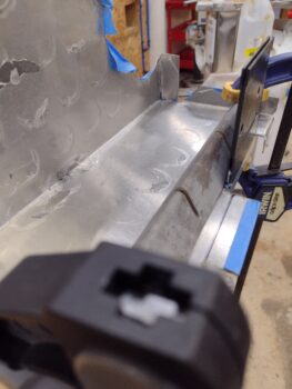
Below is the original bolt sitting on the C-clamp, and the Grade 8 equivalent clamped up to have the head drilled to take safety wire.

I didn’t mess around with trying to go through a corner, but rather went straight through a wrench flat… Success!

I then installed the new bolt, got the alternator positioned and then torqued it to spec.  Once in, as you can see, I got this sucker safety-wired up.

Now to digress a bit from engine stuff.

A while back I was looking at some various airplanes at the airport, including a Long-EZ, and noticed the seeming lack of STATIC ports on Long-EZs… clearly because the plans simply has an aluminum tube in the side wall with 3 tiny holes drilled into it.  I had planned on using more traditional static ports but as I thought about it, I liked the look (or “non-look”) of nearly imperceptible static port(s).  To be clear, I’ll note that the plans only has a static port configured on the left side.

In a recent discussion with Marco, I circled back to the plans style static ports and asked his opinion on going with one side only or both sides more in line with a traditional light aircraft (or quite a few out there I should say).  He was of the opinion that for a plane that is IFR capable it should have 2 static ports, one each side.  I point out this discussion because beyond observing what other planes have, I’m going to admit that I don’t claim to know the in-depth dynamics of one vs two of these suckers.  And honestly I’m not going to take the time to do research, so Marco’s kung-fu wins out here by default and I’m cramming 2 of the original style static tubes in my bird… one each side.

Thus, I pulled up Chapter 13, cut two 6″ lengths of 3003-0 tubing (plans calls out 5052, but I didn’t have any on hand) and cleaned them up.

I then crimped the ends on one side, flattened the outboard side a bit (to make the tube more “D” shaped, with the flat side going against the inner skin of the outer wall.  I then bent the tubes as I thought they would need to be inside the avionics area [that changed in rather short order… ].

Now, many, many years ago I had marked the sidewalls with the plans position for the static ports.  I’ll note that I have the more traditional looking ones actually on hand and those things are just under 1″ around max on the exterior side, much less than that coming through the sidewall.  One thing I wasn’t expecting (unintended consequences) was having a clearance issue with my embedded rudder/brake cable conduit and the now longer height-wise static tube.

This caused me to have to move my static ports up about 1/2″ from the plans position. Deal breaker?  I highly doubt it.

I spent about 20 minutes each side drilling the starter hole, then digging out the foam and increasing the height of the hole so the static tube would sit flat against the inside surface of the outer sidewall skin.

Before I micro’d the static tubes into place, I used my shop light to shine through the new holes/slots to mark the outside of the nose to establish a “drill line” where the 3 holes will get drilled (which I’m pondering the number now that I have 2 static inputs).

I then whipped up some wet micro, as per plans, and poured it into the static tube holes before then reinserting the static tubes into the wet micro.  Since a good bit of both holes are below the exiting tube, I simply used a piece of tape to keep the micro from running out and the tubes in place.  Tomorrow I’ll add more micro and probably a small patch of BID across the extended oval-shaped hole.

Here’s the left side static port.

And the right side.  The tape and popsicle stick is to keep the static tube flat against the outer skin.

I then got to work on the right aft lower baffle bracket, what I’ve been referring to as the “Melvill” baffle bracket.  I gooped up the lower and forward edge, as well as around the large engine bolt, before bolting the bracket into place.  I then safety wired the bolts.

Again, another minor yet important task complete!

On the left side I actually kicked off the no-kidding baffling installation by riveting the lower aft baffle segment to the underlying bracket (pic below)… Now, beforehand I did goop up the front edge tabs that go against the inner baffles.  After the rivets were installed, and I then taped up the area around/over them to protect against the black goop (RTV).  I then finished gooping up the front edges and corners of the left aft lower baffle.

I waited well over an hour to let the goop set up and then carefully pulled the tape off the top.  Some of the goop had cured fully and was rubbery, while some of it underneath was still wet and would cause a mess requiring cleanup.  Overall I think it looks pretty darn good (note the inboard rivets).

Tomorrow I’ll get up underneath the baffle and goop up all the seams from the underside as well.  I also plan on getting the right aft lower baffle installed, and… who knows?  Maybe the topside baffles as well!

Chapter 23 – Alternator installed

I actually installed that darn alternator 3 times! But let me digress and start from the beginning…

I started out today trimming and rounding the lower aft right baffle’s outboard mounting tab.  I then copied the tab’s shape onto a scrap piece of 2024 0.032″ baffling material to cut out a reinforcement doubler for the tab.

I then drilled the screw hole and riveted the doubler into place.  Another minor yet important task complete!

I then measured out and determined the rivet spacing on the left baffle inboard side.  Once I got the spacing dialed in, I then drilled the 3 future rivet holes and Clecoed the baffle to the bracket.

I then did the same thing on the right aft lower baffle.

Here we have the aft edge alignment between the left and right aft lower baffles… I have to say I like this stylistically, and thankfully Mike incorporated it into his “Beasley Baffles.”

I then focused on getting the B&C L40 alternator installed.  It was definitely an iterative process for getting both the alternator installed (especially with the crazy amount of tightness B&C calls out for on a new belt!) and getting the aft left baffle face alternator opening trimmed for the alternator to fit in there correctly.

Well, the third time is a charm!  Here we have the actual final baffle trimming complete with the alternator installed and belt tight as can be (since it’s a new belt).  Yes, there is a bit more of a gap on the bottom side of the alternator with the baffling, but as the belt stretches and the alternator is moved down a bit to keep the slack out, I think it will all work out over time.

In addition, I got the engine-side alternator bracket bolt safety-wired as well as the left side baffle bracket screw.  I do have the alternator-side bracket bolt yet to safety-wire.

I also needed to take out the “V” between the exhaust pipes on the right side baffle outboard/aft face (skirt”) to allow clearance for the crankcase vent tube that will be nestled in between the pipes on the top side.

Also note yet another right-side baffle securing screw (just below the clecos) that secures the baffle face to the underneath Melvill bracket.

Finally, we have shots of the baffle-to-pully clearance on the left side with the alternator installed, and on the right side as well.

I’m hoping to get these baffles no-kidding installed, gooped up at the seams and perimeter sealing material attached over the next few days.

Chapter 23 – Aft baffles: Closing in!

Today was about no-kidding getting the left and right aft lower baffles segments dialed in and very close to their respective, and colllective, final positions.

I started out by mounting the lower cowling to check clearance on both baffles sides.  Each side needed trimming at the bottom curve to provide clearance closer to a 1/2″.  The outboard areas needed more trimming as well to allow the exhaust pipes to come further inboard.

Also, the aft vertical 90° “outriggers” on both sides needed some trimming as well since they were both too close to the inside cowling surface.

Here are the trim marks on the aft vertical 90° “outriggers”… both sides were much too close to the upper cowling.

I then did some more work around the starter, and specifically on the B&C cross-brace betwixt alternator and starter.  This brace will be touching metal (or washers) on both the starter and alternator side as if it were mounted normally (if there is any such thing on a Long-EZ!!), the difference being now it will pin down the aluminum baffle edges in its center area between the bolts.

Also note that I drilled a screw hole at the top (seen through the flywheel balancing hole) and mounted a K-1003 platenut on the left baffle edge, to allow securing the two baffle segments together.  Besides the sealing material along the bottom edge of both baffle pieces, I also intend to install a rivet or two along the seam, below the cross-brace.

Another shot of the starter, mounted cross-brace and upper baffle seam screw.

I then spent some time on the outboard sides of the baffles, securing those to the aft vertical baffle walls once I got the positions dialed in.  Once the holes were drilled, I used clecos to tie them all together.

I also spent a good little bit drilling the outboard mounting screw tab to get the position and elevation as correct as possible on the right side (note: the elevations on these baffles are definitely not perfect, but functional and Pretty Darn Good!)

With the left and right aft lower baffle segments pretty much in final position, I measured the gap between the aft face of the baffles and the pulley on the flywheel at ~0.24″ minimum, so I’m good on clearance.

It was time to check my exhaust pipes’ positions, and to do that I needed the lower cowling back on since it has my left inboard exhaust pipe alignment mark.

With the bottom cowling mounted, I then confirmed my exhaust pipe positions and the clearance between cowl and the bottom edge of the baffles were good.  All checked out.

Here we have the lower center section —alternator and starter area— of the aft lower baffle(s).

I then installed the spinner lampshade flow guide to check how everything looked and again to take a look at the exhaust pipes in relationship with the flow guide, etc.

I then set the top cowling in place to check the clearance between it and the aft vertical 90° “outriggers” on both sides.  On the left the clearance is ~3/4″ while on the right it’s a bit less.

Then a shot each side of the overall look if one were to peer into the cowling.  And yes, my pipes still need work (I’ll reiterate that I am now convinced that these are the WRONG pipes for this cowling-engine configuration).

Inching forward . . .

Chapter 23 – Baffles: A new look

I started off correcting a minor alignment issue on the right aft lower baffle that was causing a bit too much of a gap between the inner CF cylinder baffles and the front edge tabs of this baffle.

Simply put, the outboard mounting tab was too far forward and thus pushing the aluminum baffle away from the cylinder and causing the inboard gaps.  The mounting tab needed to come aft about 3/16″, which meant re-bending it.  Which of course meant bending it back straight first.

Once back straight, I needed to trim about 0.150 off the top to allow using my Mini metal bender since it only has a 1″ depth on the deep side (3/8″ on the other side).

I then re-bent the forward mounting tab.  It’s hard to gage exactly when bending this aluminum sheet, and definitely got close enough… optimum would have been about 0.030″ closer to my line, but this will definitely meet my requirement.

I then set the aft right lower baffle back into place to check the fit along the front edge.

With the front side gaps good, I then proceeded to cycle through getting the inboard edge and the starter opening dialed in.  That took a good half dozen times removing the baffle and taking a trip to my Dremel tool station.  I eventually got it, and barring a few very minor touch-up trims, the aft lower right baffle is now fitting rather well in its location.

Here’s a closer up view of the front side edge of the aft lower right baffle.

I then went back and did some minor tweaks on the left side, and here it is set into position as well.

And a shot with both left and right aft lower baffles in place… remember, they’re not mounted so these positions aren’t exact yet.

And a shot of the lower, intersecting baffle skirts around the alternator and starter.

Speaking of the alternator, I had to buy a new, longer bolt since I want to mount the alternator-to-starter reinforcement bracket on top/aft/outside of the baffling.  Not only will this allow the baffling to have a more comfortable clearance with the flywheel pully bracket, but will also help secure the intersecting baffle edges together.

With both side aft lower baffles looking good, I then pressed forward with finalizing the aft vertical baffles’ configurations.

Here we have the alignment mark on the aft left vertical baffle with the aft edge of the lower baffle (in the background).

I then bent the left aft vertical baffle on the metal brake to create a tab facing 90° outboard…

As can be seen here.  I then transferred the fitted cardboard tab that I cut out last week to this aluminum vertical baffle tab… and then trimmed it.

Now, there is a bit missing on the bottom which I will fill in when I but the reinforcing 90° angle bracket on the “back” side (technically forward) of this corner.

I then repeated the process for the aft vertical baffle on the right side: creating the 90° outboard-facing vertical tab, then trimming it to shape.

The right side too will need a minor addition on the bottom.  Again, that will attach to the reinforcement right-angle piece that will get riveted into the corner.

Here we have a shot of the current baffle situation.  I plan on getting these things mounted soon, then getting the flexible baffle seals mounted to the edges of all the aluminum baffle walls to finish the job.

Pressing forward!


Chapter 23 – Baffles ‘bent into shape!’

I started off today with 2 tabs left to bend on the front of the right lower aft engine baffle. Since these tabs are situated on the interior of the front edge, with an obstruction on both sides, I needed to figure out how to get the very useful bending tool into that interior edge.

My solution was to simply cut off a 3.6″ wide section of the 12″ wide metal bending tool.  This would allow me to get the wider outboard tab bent downward 90° and subsequently out of the way for then bending the narrower inboard tab down 90° as well.

I drew my cut line and grabbed my cutoff grinder and got to work.

I will say that this is a robustly thick tool as it took me a good 15 minutes to get a nice cut all the way through… but persistence paid off and here we have the 3.6″ section of the metal bending tool, or what I’ve now dubbed the “Mini metal bending tool.”

I then clamped the right lower aft engine baffle inverted on the workbench just so that the edge was hanging off, and then used the new Mini metal bending tool to bend the tab downward (up in the pic) 90°.

Here’s the end result of that bending action:

I then did the same thing for the inboard interior tab (right side in below pic) and bent it downward 90° as well.

Thus, here we have the right lower aft engine baffle with all the required tabs bent into their respective positions.

And the same for the left lower aft engine baffle… all tabs bent as needed.

I also spent a good 20 minutes on the first round of trimming the required areas I had annotated before, to get this baffle segment to fit in place correctly (I’m sure there will be more trimming sessions no doubt).

Before removing the alternator, I figured out where my safety wire runs were going to terminate.  I then made a mark at each of those 3 positions.

And then drilled those 3 holes with a small drill bit to allow for safety wiring the 2 alternator bolts and also the bolt securing the inboard bracket for the left shelf & skirt baffle.

And with that, I called it a night (I’m also slowly cleaning the rust off my plasma cutting table metal components in prep for using it in the near future!).

Chapter 23 – Bending aft baffles

Today I started down the road of bending up the aft lower baffles to get them fitted onto the engine and hopefully put the engine baffles in my rearview mirror in short order.

In addition, I’ll note that I wasn’t liking my options thus far on how to secure the exhaust pipes —both to each other in pairs and to the engine to ensure none depart out the aft cowl opening into the prop, if there ever were a crack or a break— so I took another hard look at the instructions that came with the cowlings from Mike Melvill.  It was at this point I decided to mimic closely what he did and press forward in a different direction on my pipe brackets… Melvill style! (more to come on that in the near future).

I started my baffle bending endeavors by deciding what order I needed (or could) bend each baffle without “painting” myself into the proverbial corner of blocking the ability to do a certain bend by having done another preceding one that prevented access to it, or at least making it exponentially more difficult.

The first bend for both left and right aft lower baffles was the big 90° one on the metal brake.  Here we have the aft lower left baffle ready for bending . . .

And post bend.  Honestly it took more time marking the bend line and applying the protective tape then the 30 seconds to bend the darn thing!  I then repeated the process for the right side baffle.

Not shown in this post is the 2 front tabs on the forward side of the left aft side lower baffle that I bent downwards 90°.  These tabs will get RTV’d to the CF cylinder fin baffles to seal this lower baffle to the engine.

As you can see, the 2 outboard tabs: top and front (“shelf and skirt”) have not been bent yet.

I also checked the fit down below with both the exhaust pipes and the alternator.  I could tell by the alignment with the alternator that the outboard top corner of the baffle needs to come down about 1/8″ while the entire baffle needs to be rotated CCW to do that.  That will require some judicious trimming around the inboard baffle edges where it meets the cylinders… trimming notes already annotated.

I then mounted the CF 180° air induction intake tube to do a fit check with the baffles.  Here I’m holding a piece of cardboard up against the back apex of the air induction tube to check clearance with the new lower baffle.

It may be a bit difficult to see the aluminum baffle…

Which is why I grabbed these progressive shots below, to show the relationship between air induction intake tube and the bottom edge of the lower baffles.  I’m not worried at all here with clearance because I’m going to glass in (ok, CF) a mini-bulkhead wall into the lower cowling that will sit just aft of the air induction tube and stop at a height about 1/2″ below the aluminum baffle skirt.  Clearly the sealing material on the bottom side of the aluminum baffles will then seal against the top edge of the bulkhead (aka “aft bottom cowling reinforcement rib”).

Beyond the big 90° bend on the right side aft lower baffle, I did a bit of the opposite as far as the perimeter tabs are concerned:  I did the one upward bend along the front edge, which is the tab where the baffle gets physically mounted to #2 cylinder via a screw.  I also bent the 2 outboard tabs (top: down and front: forward).

Just as on the left side, I’m using a sheet metal bender that is common among HVAC guys for working sheet metal ducts.  If the material is clamped properly, this basic tool is quite handy and works a treat.  No issues so far (knock on wood!).

Here we have the top tab bent down 90° on the outboard side of the right aft lower baffle.

And then the front tab bent forward 90° on the outboard side of the right aft lower baffle (note the upward bent baffle attach tab on the right side of pic).

Although all taped up to prevent any untoward scratching, I grabbed this shot of the right aft lower baffle.

It was getting late and Jess was over making dinner, so I called it a night.  Tomorrow I’ll bend all the remaining baffle tabs and then dial in each side to fit.  If all goes well I might actually do the final install of the alternator with belt tensioned correctly as the left side baffle gets installed.

Chapter 23 – Engine Turned Baffles

Today I finished Engine Turning all the major baffle sections on the engine that I’ll be doing.  Here we have the lower left aft baffle just completed.

I set the lower left baffle in its approximate place and then prepped the lower right aft baffle for Engine Turning.  The lower right baffle is patient zero—the one that had the scratch that drove this entire Engine Turning craze!  As you can see in the upper right hand corner where I buffed it out.

A few hours later: Voila! the lower right aft baffle is complete with its Engine Turning as well.

And another shot of the all the major aft-facing baffle walls Engine Turned.

As I note in the video, using the method I used the 6061 aluminum didn’t turn out as spiffy keen as the front 2024 baffle panels.  They still look very presentable in my opinion, but they certainly show a lot more rings in each individual circle.  That being said, the offending scratch is virtually gone and these things are still functional… and will be somewhat obscured in the engine compartment, so I’m done worrying about them and pressing forward!

I documented my Engine Turning journey in this mini-documentary (haha… ok, it’s just a video!).  Enjoy!

Next I’ll be bending the aft lower baffle segments to get them mounted into place.  The upcoming “wings” on each outboard side of the upcoming installed lower “shelf & skirt” baffles may very well get Engine Turned as well, but that’s as far as I’m going on the engine baffles…

But how about those outboard CS spar Titanium firewall sections?  Hmmm?


Chapter 23 – Engine Turning Baffles

As I get back onto my build and focus on getting the airplane completed, along with that I also have a goal to get all my shop tools online, maintained and dialed-in as they should be.  Obviously having an immediate job that requires their use makes it easier to focus on a given tool.

And thus it is with this week’s “power tool of the week,” to focus on: my standing drill press.  I started this endeavor a couple nights ago as I scrounged around a couple of hours off and on to find the parts box.

The next day I spent well over 2 hours cleaning and removing a good bit of the rust off the drill press, especially the chuck which was a solid chunk of rust after going through the hurricane back in 2019.  By the time I got the drill press to my shop (from my old hangar) back then, it had all the handles, belts, etc. in one box, and the chuck in a bag of solvent to remove the rust (in the garage).  I then never assembled it or used it, and am just getting to it now.

After putting a nice scratch on the lower right engine baffle as I was drilling a relief hole, I was assessing my best options to remove the unsightly scratch.  It turns out that as I was on the COBA forums earlier reviewing posts on engine baffles and exhaust systems (aka “What would Klaus & Marc Z. do?”), someone posted a shot of their firewall that they had just finished Engine Turning (or “jeweling”).  This was pre-scratch so I simply filed it away in my mind as a point of interest.

Someone else on that forum thread placed a link to a pic of the Spirit of St. Louis, which is a great example of engine turning on the cowls.

Post-scratch:  To be clear, I like the nice smooth look of aluminum baffles around the engine.  But I was going to have to do something to remove the scratch, and clearly that baffle segment wasn’t going to look the same after the scratch was removed… and would very well likely need the entire baffle buffed out to blend the scratch in.  After spending a good couple of days blending the paint in on Guy Williams’ Long-EZ as I repaired its winglet, blending anything at this point was not something I wanted to engage in.  Thus, Engine Turning became my answer to resolve the scratch issue.

After a good round of research on how folks were doing it, I then tried my hand at Engine Turning on a scrap piece of aluminum…. looking pretty spiffy to me!

I then decided to Engine Turn all the baffle surfaces that face reward on the engine and that would be somewhat visible when looking into the cowled bird.  I started my no-kidding Engine Turning adventures on the front left baffle segment and got this far before calling it a night.

I finished the first big top forward baffles today… here we have 2 of the 3 front baffle segments Engine Turned.

Jess was sweet and cooked me dinner over at her place tonight, but before I left to go over there I was able to finish the last segment of the front engine baffles.  Here are all 3 front baffle segments Engine Turned.

Tomorrow I plan on getting the 2 aft lower baffle segments Engine Turned.