Today I cut the right aft lower engine baffle out of 6061 aluminum.
Unfortunately I dove in without drilling the relief holes at the bend edges, so I had to do that after the fact on a couple of them. Over towards the mid-right side as I was coming in from the edge the drill slipped and went across the face of the baffle, placing a decent-sized scratch on it for a few good inches. Soooo, I’ll have to see if that buffs out. If not, I think I have a backup plan to eliminate the scratch.
I then headed into town to pick up a sheet metal bending tool from Harbor Freight, but alas, they were sold out. I ended up grabbing some Thai food with Jess, and then headed home with a handful of stuff from HF, but not what I had ventured out for.
After doing some online searching, I ended up ordering the sheet metal bending tool off of Amazon.
I then spent a few hours doing some research on my next steps, as well as gathering up (read 45 min looking for!) all the pieces/parts to get my drill press back online —which I haven’t used since I moved into this shop nearly 5 years ago.
A significant milestone in cutting this thing out, now to get ‘er installed. More to come!
Today was all about moving out on the baffles. In fact, my goal is to have the baffles COMPLETE by this coming weekend.
One thing I’ve been pondering for quite some time now is how exactly to work the sides of the baffles: my decision being between leaving the side baffle segments long and extending them aft, or creating little mini-walls on the outboard aft side of the aluminum baffle segments to close off the air coming along the side.
I decided on the latter.
In doing so, I measured and marked where these mini-wall baffles would be, then marked those positions on the upper cowling. Using contours of the inside upper cowling, I then made some initial baffle mini-wall templates and taped them into place on the left and right sides.
I then put the top cowling in place, used a shop light to check the mini-wall baffles vs the top cowling sides, took the top cowling off, trimmed the mini-wall baffles, then repeated the whole process…. a good number of times. It’s an iterative process!
But I finally nailed down the configuration for both the left and right side mini-wall baffle segments, which we have right here:
Before doing any cutting or brake bending on the side baffle segments, I wanted to have the no-kidding position of each lower aft shelf and skirt baffle segment in place first.
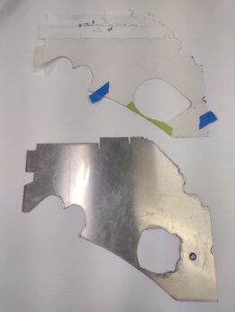
I started with the left side and traced the template onto the 6061 aluminum sheet.
It may be a little hard to see here, but the lower aft left baffle segment is ready to be cut out of the 6061 aluminum sheet…
Which I did next. Here we have the left lower aft shelf and skirt baffle segment cut out and ready for clean up and then some bending on the brake.
I then placed the template for the right lower aft shelf and skirt baffle segment on the 6061 aluminum sheet and traced it out.
Here’s the lower aft right baffle segment ready to be cut out of the 6061 aluminum sheet.
It was getting late so I decided to call it a night and will cut out the right side lower baffle tomorrow. I also plan on doing a good bit of bending these aluminum segments on the metal brake as well.
First off, I’ll regale you with a quick story: Fall 2013 and I’m in the middle east. I ask Mike Beasley where he bought his exhaust pipes from, and he sends me the link to Custom Aircraft Parts with the part number he bought. I send an email to Clinton detailing my bird’s cowlings, engine, etc. and he spits out the same part number as Mike’s. I know realize the key piece of information that I added to my email that tipped Clinton off to that part number was “Feather Light” and am almost certain that is why I received the pipes that I did. The actual key wording that should have been focused on was “Mike Melvill’s carbon fiber cowlings“… because although Feather Light made the Melvill CF cowlings, they were nowhere the same as the stock Feather Light cowlings (I’m guessing those were close to the Task cowlings, which I’m pretty sure is what Mike has).
I figured all this out from the multiple comments on the COBA forum while I was researching baffling and exhaust pipe configuration stuff. I should have opted for the Cozy exhaust pipes that have a significant S-curve up and then straight rearwards immediately aft of the cylinders… not the gradual curve that Mike’s and mine have, although I’m having to significantly modify mine. If I knew then what I do now, I would have demanded a swap-out for different style (part number) pipes.
Ok, part of my research was Klaus discussing that having your exhaust pipes separated about 1/2” apart is best since it keeps the vibration/harmonics/pressure waves of the pipes and exiting exhausts from affecting each other.
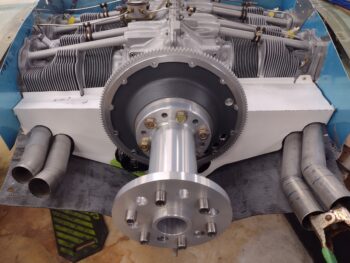
Now, back to Custom Aircraft Parts for a moment… if you look (closely) at Mike Beasley’s exhaust pipes you see a rounded “W” looking clamp that secures the pipes together (Dave Berenholtz and many other canards have these too).
[Also note the center crankcase vent tube in between the pipes… it comes into play]
Here’s a look at the bracket from Custom Aircraft Parts. The PRO is that I’m certain that it’s well-made and it does the job. The CON is that one pair costs $275, and that’s without shipping. Clearly to do both sets of pipes we’re talking around $600.
That dog will NOT hunt! Sorry, I’m not paying nearly $600 for these brackets, nor am I going to pay around $300 for one bracket pair.
I’ve already ordered the stainless steel from McMaster-Carr to construct a bracket pair for the RIGHT side, and the 1/2″ round tubing I’ll be using to create a securing brace for both sides. Moreover, I also ordered 321 stainless steel “P” clamps (AKA bare Adel clamps) for the LEFT side, all for just over $60 bucks (including tax and shipping).
Taking Klaus’s words of advice into account, I then modeled up a set of brackets in Fusion 360 CAD to test out his 1/2″ gap configuration.
I then 3D printed a narrower width version (0.4″ wide vs 0.75″) of the brackets to save both printing time and plastic. Here’s the result:
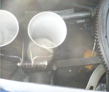
I then test-fitted the brackets onto the left side exhaust pipes. The 1/2″ gap between the pipes drives the outboard pipe out too close to the upper cowling wall, so I’m going to have to pass on his advice and go the more standard method that is seen in most canards (pipes nestled together).
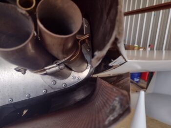
I then cherry picked through my stock of Adel clamps to find one that fits the 1.75″ dia. exhaust pipes spot on, which is the -25. This was merely a test fit as the potential issue here if I were to use an Adel clamp is that they are aluminum (from ACS) and their ability to fend off the intense heat of the exhaust pipes is —in my book— suspect. They do make stainless steel versions of these style clamps, which is what I ordered from McMaster-Carr.
Although I only have one clamp installed below, in the final configuration I’ll have one on each pipe, mounted back-to-back and secured by a 1/2″ brace that will serve to keep the exhaust pipes in position during normal ops, and also keep any pipes from exiting the cowling should either of them crack/break free.
As a point of reference, here is a shot of Klaus’s exhaust pipes… note the P clamps securing his pipes.
Finally, the reason I’m not using the “P” style clamps on the right side exhaust pipes is simply due to the crankcase vent tube that will nestle in between the pipes to create the lowest profile of this grouping as possible.
Last night I got my air compressor oil change and maintenance tasks finally completed, with some test runs to ensure the pressure valve was working correctly. All looked good.
I also took out the oil heat sump street fitting with standpipe to do some “spot welds” on it just to ensure it’s physically fit for duty in the engine.
Today I got back to work on the aft/lower engine baffles by putting the thick paper templates back in place. I made notes and trimmed the templates in various spots as I worked to dial in the final configuration of the lower baffle “skirt.”
After removing the aft/lower baffle templates, I figured it was time to add in the last reinforcement piece to the “Melvill” baffle bracket that mounts to the aft right side of the engine.
I scrounged around for the best piece of scrap left over from the VANs baffle kit, made up my tape template on the bracket and then transferred it to the scrap aluminum piece. I then cut out the reinforcement plate and bent the tabs on the metal brake.
Here we have the reinforcement tab riveted to the Melvill baffle bracket, with the bracket reinstalled on the engine.
And yet another lower view of it. Another task, of a myriad left to do, completed.
I then mounted the top cowling to capture all the tasks I need to finish on that, and take a hard look at the final exhaust pipes configuration. Assessing my exhaust pipes once again, I’m still convinced that these are the wrong pipes for my setup: a case where I (the layman) am correct, and the vendor is plain wrong. Which at this point means nothing now other than working the problems out.
After analyzing the exit positioning of all the exhaust pipes, I came to the painful conclusion that I’m going to have to once again cut the left outboard pipe to angle it both inboard and down a hair —so that it nestles in very close to the inboard pipe in its position below.
The right side exhaust pipes will be workable, with the only drawback being the position of the aft final bend in the pipe… which happens to be right where I need to trim them. The cut will either have to be a bit further in than I want (~2″ inside the cowling), or I’ll have to live with the aft pipe openings pointing outboard much more than desired.
Over the past week I’ve been involved helping my local Canardian buddy, Guy Williams, fix his Long-EZ that was damaged during its annual condition inspection, when the A&P pulled the batteries out of the nose without it being lowered first… Oops! And yep, up it went on its backside.
The nearly horizontal prop got a ding on one end, which Guy removed, boxed up to send to Joe Person for repair, and replaced with a spare wooden prop.
The lower aft winglets were next on the list of damage, with the right getting off fairly easy while the left took the brunt of the impact: cracking the tubular taillight housing, these being added to the bottom of the lower winglets by original builder Frank Tifft.
Here’s the right lower winglet with some minor cracks, which I filled both internally and externally with micro and flox.
Again, the damage to the left lower winglet was much more extensive and required sanding off the paint to expose all the damage.
Apparently neither Guy nor I got a shot of the left winglet’s damage, but my first task was to get all the cracked “jigsaw puzzle” pieces micro’d/floxed back into place and the original shape reestablished. I then did a 1-ply UNI wrap layup to secure the reassembled structure to the existing lower winglet. That did the trick and it was plenty strong with minimal added weight.
Also not shown was the remaking of half the top and the complete bottom taillight standoffs that are located at the upper and lower side of the light bracket at the screw mounting positions. After creating templates of the right light assembly, I made the new taillight mounting standoffs out of 1/8″ thick G10 phenolic and floxed them into place.
After an overnight cure on mounting standoffs, I slathered up the lower left winglet with micro, and cheese grated it about 3-1/2 hours later.
The following day I sanded down the micro to its final state, and then applied 5 epoxy wipes as per the Corey Bird finishing method. We then let that cure overnight as well.
After sanding down the epoxy wipes and blending that into the existing winglet paint, I then hit the repaired area with a couple coats of primer.
I then shot the lower left winglet with some color-matched Nasson paint that we picked up at Napa Auto Parts.
The blending is always the hardest part when you’re repairing a smallish area on a much bigger painted surface. Even though when I shot the paint I kept peeling back the tape to expose more of the original surface, there was a bit of a hard paint line that was distinct between the old and new paint.
I told Guy we could let it cure and see how the paint levels out, or try to blend it more. He wasn’t too keen on the distinct line between old and new paint, so I very carefully went sanded the junction line, prepped the old and new paint surfaces and reshot the yellow paint to blend it in more.
Here’s the result. It’s very difficult to see any difference on the inboard side of the winglet.
Admittedly, I am NOT a master painter, and the outboard side of the winglet looks really good, albeit the blending did leave a hair flatter surface towards the front lower side of the winglet that can be seen if you’re looking more critically at the paint.
In the pics above and below the taillights have been successfully reinstalled (note the light brackets were stripped, primed and repainted as well).
As both Guy and I quipped at the end of our repair effort: Good enough for government work. Time to get this bird back in the air! … and for me to get back to getting my bird in the air.
Today I spent a good chunk of the day repairing Guy Williams’ dinged up Long-EZ at the airport. Upon returning home I wanted to get at least one task knocked out, and with the new 45° street elbow and 90° AN hose fitting looking promising, I rounded up my oil heat system feed oil hose and tested out the length.
I knew it would be too long with the new fitting situ as it is, so I pulled back the fire sleeve and marked the cut line. In retrospect I should have cut it about 1/4″ shorter, but this dog will hunt.
I then installed the new 90° AN hose fitting, trimmed and safety wired the black fire sleeve in place, and finally added heat shrink over the exposed end to tighten it all up… Voila! The oil heat feed hose from oil sump is remade and the configuration is looking pretty darn acceptable (clearance always could be better).
And better still I didn’t have to move the fitting on the firewall!
I then spent well over an hour doing some much needed maintenance on my shop’s air compressor, including an oil change. I still need to check one of the main out lines to ensure there’s no leak… I’ll need this compressor soon for finishing the paint on the bird.
Yes, my friends, it’s been quite a few months since I was on this build. Dealing with the cold weather I got into a couple of other projects, one of those being getting engaged to Jess.
Yada, yada… time to get back to building.
My first task was swapping out the desiccant in the plugs on the engine. I broke yet another one so I taped it into place with green painters tape. Hopefully this is sign that I won’t need them soon?! (wink)
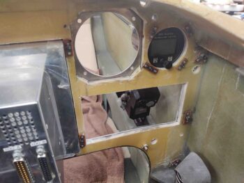
I wanted to clear some “low hanging fruit” off the proverbial build tree before jumping back into some major tasks. Over the last couple of days I modeled up an outline of my new 360 Avionics Mini-Uni 2 EFIS in Fusion 360 CAD to provide me a cutout template for the original composite panel. I also verified fit and mounting screw hole size by checking the Mini-Uni 2 with the aluminum panel.
My first effort 3D printing the cutout template is the one on the right, which is a 1/2″ thick. I then tweaked the corner chamfer sizes to match the actual EFIS unit’s, and then reprinted another version (left side) only 1/4″ thick.
As you can see, the dimensions of the 1/4″ thick 3D printed composite panel cutout template came out nicely.
I then did a general check of available spacing behind the panel for the EFIS.
And set the cutout template in space on the front to check I had enough clearance (barely, as par usual) to trim out the material.
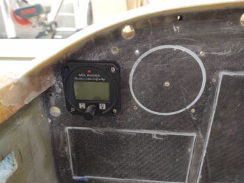
I’ll remind ya’ll that I had surface mounted the MGL clock that was in this position, with #6 nutplates floxed onto the back side of the panel to thread the screws into.
I knocked the four #6 nutplate assemblies off the panel and then proceeded to cutout the area needed to fit the 360 Avionics Mini-Uni 2 EFIS. To be clear —as I noted months ago— I wanted to ensure that not only with this instrument swap, but that in the future I could install virtually any 2-1/4″ instrument without having to remove all the instruments and aluminum panel to do what I’m doing now… making a lot of dust and mess!
I left the existing upper outboard screw hole tab of just the carbon fiber top skin of the original composite panel in place so I could verify fitting with the EFIS mounted to the aluminum panel (only), and having the required clearance with the composite panel.
The one fly in the ointment regarding clearance was my Autopilot “EFIS vs GPS” nav source switch. Although this switch is a mini-switch, it has 9 posts on it and is fairly robust in size.
After some pondering and evaluation, I decided I’m not messing with moving the AP nav source switch on the panel, and that the EFIS was going to have to sacrifice a bit to make this work.
If you look closely, the case of the EFIS is actually 3D printed (not by me), and is actually fairly thick, about 0.075″. I determined with the case thickness removed and about another 0.07″ shaved off the aluminum front bezel, I could reclaim the clearance required for the switch and press forward.
After I carefully removed the case and looked at the internal boards, and the screen components, I ascertained this could be fairly easily accomplished and set to work.
Here’s a test fit back in the panel after the surgery on the mini EFIS.
I then took the Mini-Uni 2 EFIS into the house and test fitted it into the panel with the actual switch… Voila! The plan was successful.
Another couple of shots of the mini EFIS switch clearance notch with the switch in place. Of course I’ll put some tape over the EFIS notched hole when I install everything to seal the case up. I’m very pleased with how all this came out.
I then got to work draining the oil out of the engine.
My plan here was to get the oil sump oil preheater from Anti-Splat Aero installed and off the to-do list.
On the front right corner of my Superior Cold Air Induction oil sump is a horizontal port that had a threaded hex seal plug in place, from the factory. I removed that steel seal plug and cleaned off the sealant and oil in the threads with acetone.
I then gooped up the threads on the oil sump oil preheater and installed it. Voila! Another task complete.
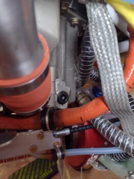
I then moved onto the bottom left side of the oil sump, where I had the rather robust steel 90° oil heat system outlet fitting installed. Note that I do not have the hose bracket installed into the ram air induction can since I cannot mount the orange SCEET tube with this behemoth steel 90° fitting installed… it has to go.
Another reminder: welded to the 90° steel fitting is a standpipe to ensure that the oil heat system will never syphon too much and always leave the engine with at least 3 quarts of oil in the oil sump. I removed the steel fitting and measured out the height of the standpipe (~4.5″) and then marked the new replacement brass 45° street elbow with to trim its attached standpipe to the same height.
I then installed the new brass 45° street elbow fitting into the engine oil sump port HAND TIGHT to check fitting and clearance with the orange SCEET tube (note mounting bracket back in place on the ram air induction can). Again, although not optimal clearance, but once I torque the fitting into place I’ll have about a 1/4″ clearance. As with all other components, this too will be monitored closely during the 40-hour test flight period.
A caveat on my being “back on the build”. . . My local Long-EZ canardian buddy, Guy Williams, had a mishap during his annual CI last week when the A&P took the batteries out of the nose without his short-nosed EZ being in the grazing position… yep, popped right back on the winglets and crunched them a bit (not too bad). That being said, starting tomorrow on I’ll be spending a few hours a day helping Guy get his bird fixed up.
I started off today by testing my removed lathe CNC control box KBSI-240D board’s MAX trimpot to see if it was working or not. After all my machinations with it installed, I figured I was going to merely confirm that it was a dead potentiometer and set about ordering a replacement.
But, as things seem to be playing out in this new year… I was wrong. I powered up the board with a homemade 120v plug and hooked up the VFD input to a 9V battery. I then tested the output with my multimeter as I manipulated the set screw on the MAX trimpot… and it worked as designed! Hmmm? Interesting. Now of course I’ll mount it back into the lathe CNC control box, double-check all the wiring, and see just what the heck is going on!
In other news, about a month or so back I reported doing some fairly in-depth research on a replacement for my MGL clock/timer on my panel. I like the display and as a clock and timer it had all the functions I wanted. But as I started pondering more and more, I wanted 2 backup functions on my panel in case either of my GRT EFIS screens went dark: a backup AI (or EFIS PFD) and an HSI/CDI to merely display ILS/LOC/GPS approaches from my GNS-480 GPS box. In short, if I lost a screen I wanted extra data display points to help ease the load and mitigate the requirement of switching screens on a single EFIS display if it ever came to that.
If you remember, I looked heavily at the Kanardia HORIS EFIS and really thought it was a nifty little unit. My initial thought/concern in replacing the MGL clock/timer —in some-what post haste fashion— is that due to space constraints in the upper left corner of my panel I have it surface mounted on the front of the panel, with #6 platenut assemblies on the backside of the panel structure to secure it. This of course works better for added instrument panel bulkhead strength, but if I ever wanted to swap this out with a “proper” 2-1/4″ instrument in the future, I would have to remove the entire panel and then do a bunch of messy cutting on a flying airplane (ahem, it WILL be a flying airplane!).
Now, the HORIS looked good, but just as with the other viable 2-1/4″ AI/clock/timer candidates out there (read: uAvionix AV-20s), none of them were fitting the bill of really what I wanted: a clock/timer first, and a back-up AI/PFD second. And while they had nice screen graphics, the timers were all in reality nothing more than simple count-up stop watch functions. This is one thing that drew me to the MGL, it had really good clock displays, but also a good countdown timer to boot for use as reminder when to switch fuel tanks.
Me being an avowed Neanderthal, the same thing proves true in my flying: nearly all done in fixed gear high wing aircraft… I don’t want an engine quitting oops simply because I forget to switch the darn tank!
Enter Vlad and 360 Avionics…
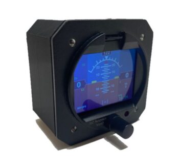
I actually found the 360 Avionics ELM 200 (MiniUni 2) on the Aircraft Spruce site. I then did a good bit more investigation. Here is a stock photo of this diminutive 2-1/4″ power house (its big brother is the 3-1/8″ MiniUni 3).
I discovered that the MiniUni2 had 97% of what I was looking for in an instrument to replace the MGL clock/timer:
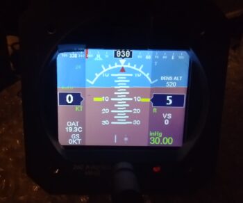
First, the AI/PFD screen has just about every bit of data you’d want in flying behind an EFIS. With pitot/static, OAT and GPS inputs it gives you all the basic airspeed, GS, TAS info along with a V-speed tape. It provides Alt, VS, D-Alt and Baro. In flight it provides your standard rate turn markers, as well as slip skid indicator. And finally it gives you True (GPS) heading (I would prefer Mag HDG as well, but this is a back-up AI/PFD).
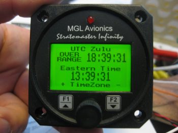
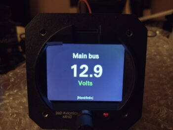
This pic below is my ELM200/MiniUni 2 sitting on my coffee table literally within 30 seconds after I connected power. I’m posting these pics in the default screen order in which they appear… I will change it up so that the clock/timer screen (shown further below) will be the first screen displayed.
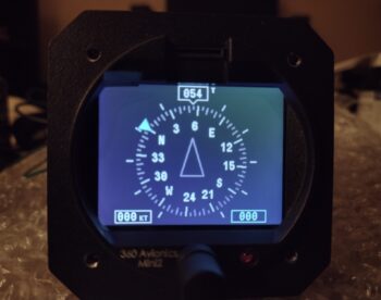
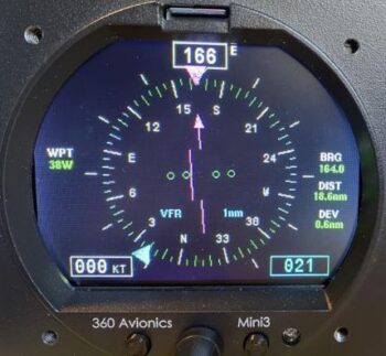
Screen #2 is the “DG,” or technically called the Compass Mode. It has a heading bug (lower right) and also displays airspeed (lower left).
As you can see, the clock/timer screen displays UTC/Zulu time, local time, flight time (initiated when aircraft reaches rotation speed), and a count-UP timer.
Whoa!! Wait a minute you say! What about your precious COUNTDOWN timer that you prattled on about? … well, wait. There’s more!
Separate to the countdown timer on the clock/timer screen above, is a menu configurable (Ez-Pz btw) countdown timer specifically for fuel tanks. Let’s be honest, you and I both know that pilots are crazed anal-retentive OCD types that tend to repeat the same processes over and over. Once I dial in the frequency to switch tanks, I doubt it will rarely change. In my book this is a fantastic little feature and fits the bill perfectly for what I was looking for.
It also has this handy little screen, although very redundant and not really required for my configuration. But good nonetheless.
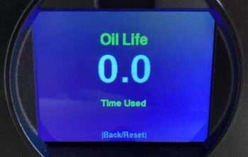
In addition, it does have this even more handy screen, which is a cumulative total of all the FLIGHT time to give you a good idea when your oil change is due.
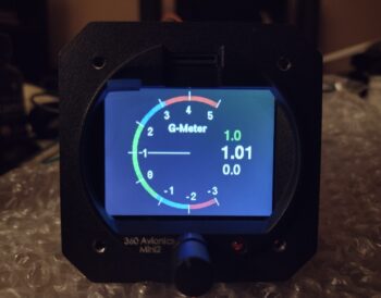
Although I don’t see using this screen below for day to day flight ops, I could see where it could definitely be handy during initial test flights and for testing out different maneuvers.
I’ll note it has a few more individual screens to display altitude only data (including baro), airspeed only data, and local time with flight timer.
Now, I had a good bit of conversation back and forth with Vlad regarding features and quality on his EFIS units. After I was thoroughly satisfied on the quality front, there was one area that I was not overly satisfied with: the MiniUni 2 lacked a key feature that the MinuUni 3 had… an ability to hook it up to your GPS navigator via a RS-232 connection to drive both a CDI, and a fair bit of GPS track info.
Well, Vlad’s a smart guy and apparently he saw this requirement being asked for in the future, so he had already been working in his lair adding those exact capabilities to the new version of the MiniUni 2. Thus, I’m happy to report that he built my EFIS as a much more “mighty” MiniUni 2 by adding these cool features.
Another feature that may not seem overly important on the face of it (uh… literally!) is how these units are updated/upgraded. Both the Kanardia HORIS and uAvionix AV-20s firmware update processes are (IMO) clunky and not elegant (i.e. a much bigger pain than desired). Conversely, updating the MiniUni 2 is fairly straightforward… it may be a bit difficult to see in all the other pics other than the one immediately above, but just above the screen is a micro-SD card slot. Simply download the firmware file from your computer to the micro-SD card, plug it into the MiniUni 2, power it up and follow the prompts.
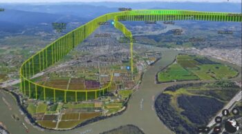
Now, having an onboard storage device in the form of a micro-SD card allows for utilizing another cool feature that Vlad incorporated into this unit (I’ll note that Vlad created a whole line of EFISs that he personally flies in his RV-10) which is called the “Black Box” function. Once enabled, this included option is a flight recorder that tracks all your flight data. You can then easily export that data to your computer and open it up using Google Earth.
Finally, here’s a video of Vlad discussing his MiniUni EFISs:
Again, this EFIS/clock/timer is my replacement for the MGL CLT-2 clock/timer, and it will be installed prior to first flight. I do have plans to replace my 3-1/8″ TruTrak ADI, which is in the works but won’t happen until quite a bit after first flight.
No, this is not frontline airplane building, but there are a number of parts that I need to make with this lathe for this build. I figure I would do a quick overview of a key issue I found, as well as my progress. Probably as much for me as a future reference as for you as an update.
Analogous to a long airplane building project, since I did a my initial stint of CNC conversion on this lathe the January before last, I had to pick back up where I left off. I completely failed to remember that I hadn’t even hooked up my spindle encoder to the Acorn CNC board. Probably due to the overall lack of ability to do any spindle manipulation since I hadn’t done the right mod to the main control board that allows me to control the lathe spindle via the Acorn CNC control system (I did this a few weeks ago).
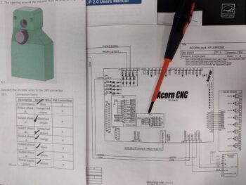
Now with basic spindle control “operational,” I need to refine it so that when I or a CNC g-code file commands a certain RPM, the lathe responds accordingly… which it is not currently doing. So today I finished a task that I started about 3 years ago: terminating the ends of the 9 spindle encoder wires with D-sub pins to create a 9-pin D-Sub plug. These 2 documents gave me the how-to on doing that.
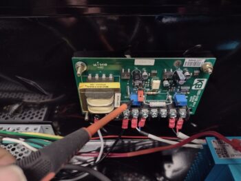
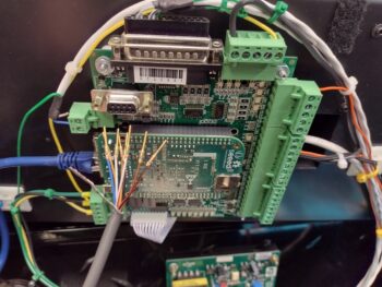
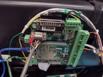
Here we have the encoder wires cut and pinned (pic 1) and then terminated into the 9-pin D-Sub connector, which is plugged into the Acorn CNC-12 board (pic 2). The red ring terminal is the shielded wire ground.
Notice the 2-post connector just to the left of the red ring terminal? That is the Variable Frequency Drive (VFD) 0-10 volt output that controls spindle motors on much larger lathes and mills than most home shops have. Most smaller hobby lathes and mills tend to use a 0-5 volt range to control spindle speed. More on that in a minute…
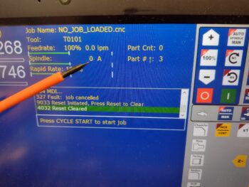
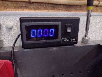
With the spindle encoder now installed, I tested out its operational capability. The good news is that it was spot-on and matched my external lathe RPM readout almost exactly as I cycled through RPM ranges by using the command line on the control screen.
The bad news is that the RPMs I was asking for on the command line screen were not being accurately produced at the lathe spindle. Again, the no-kidding spindle speed was being reported correctly by both the encoder and the external RPM display, but it wasn’t what I was telling the system to do.
Remember the 0-10 volt VFD output from the Acorn board? Well, for us home shop bubbas we tend to use a KBSI-240D signal isolator board to translate that 0-10 volt Acorn board output into a usable 0-5 voltage range to dictate lathe spindle speed. Zero (0) volts translates to a stopped spindle. 5 volts is max RPM, which in the case of this lathe is 2500 rpm.
On the KBSI-240D are two (2) trimpots: one to dial in the max voltage, and the other to dial in the minimum voltage. Taking voltage readouts while commanding various spindle RPMs has proven that the MAX trimpot ist kaput, TU, no muy bieno in that it won’t allow me to adjust the upper voltage down to 5 volts. In fact, currently it’s stuck on a whopping 12.47 volts, which is clearly no good for this configuration. Moreover, this sucker has been the hidden fly in the ointment over the last couple of weeks truly hindering my ability to get the spindle control dialed in. It makes total sense now after finding it.
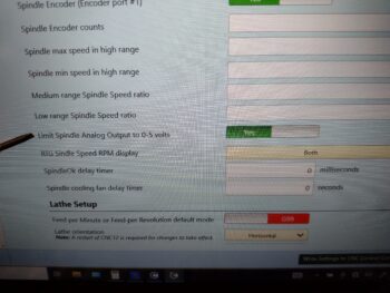
Now, a new feature in my new updated (note: not upgraded… yet) version 5.08 Acorn CNC software is that in the configuration is a menu item that allows the Acorn board to output 0-5 volts through the VFD port. I thought this might be my get out of jail free card, but alas, it did not work either when I tried to hack the system.
Thus, I pulled the KBSI-240D board and will do a final test on the MAX trimpot to see if it is truly bad. If so, I’ll order a new trimpot and solder it in at some future point. Since the lathe is currently spotty, I finally just pulled the trigger on some stainless steel rod, a M8-1.0 tap and 7mm drill bit to create my own stainless steel bungs for the compression style EGT fittings. Ones that won’t be so bulky and heavy.
Yes, during the colder weather I did want to get my lathe CNC conversion completed and get it online. I’m clearly much closer, but with the weather temps inching up as we move towards spring, I need to get back onto the no-kidding airplane build.