Chapter 3 – Lathe CNC squawks

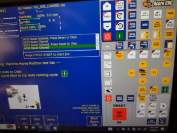
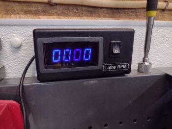
No, this is not frontline airplane building, but there are a number of parts that I need to make with this lathe for this build.  I figure I would do a quick overview of a key issue I found, as well as my progress.  Probably as much for me as a future reference as for you as an update.

Analogous to a long airplane building project, since I did a my initial stint of CNC conversion on this lathe the January before last, I had to pick back up where I left off.  I completely failed to remember that I hadn’t even hooked up my spindle encoder to the Acorn CNC board.  Probably due to the overall lack of ability to do any spindle manipulation since I hadn’t done the right mod to the main control board that allows me to control the lathe spindle via the Acorn CNC control system (I did this a few weeks ago).

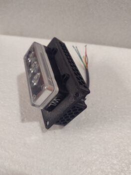
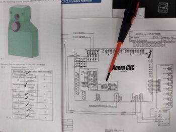
Now with basic spindle control “operational,” I need to refine it so that when I or a CNC g-code file commands a certain RPM, the lathe responds accordingly… which it is not currently doing.  So today I finished a task that I started about 3 years ago: terminating the ends of the 9 spindle encoder wires with D-sub pins to create a 9-pin D-Sub plug.  These 2 documents gave me the how-to on doing that.

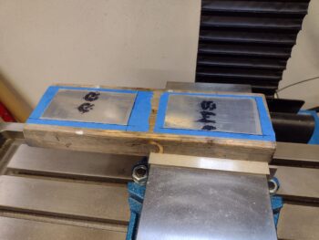
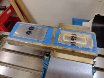
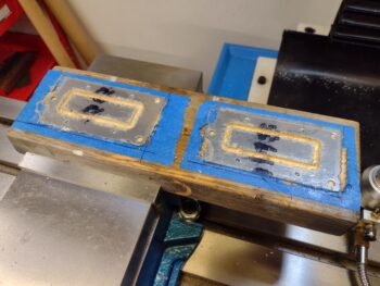
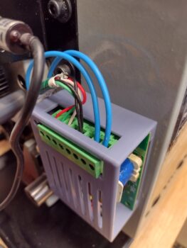
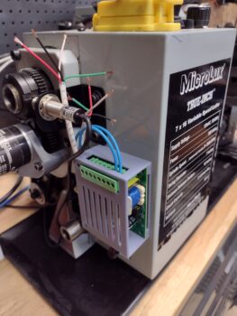
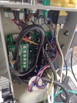
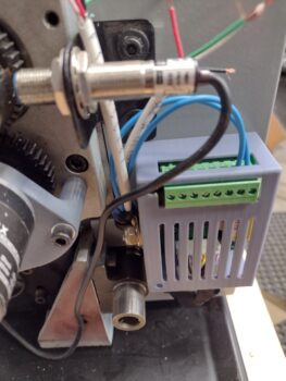
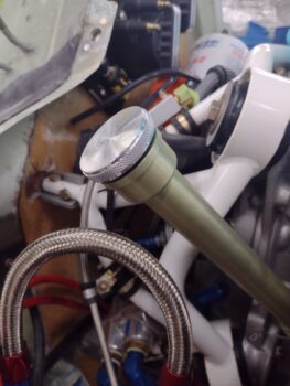
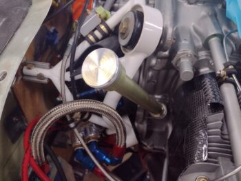
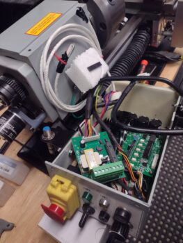
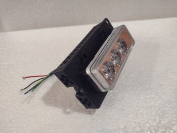
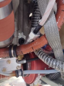
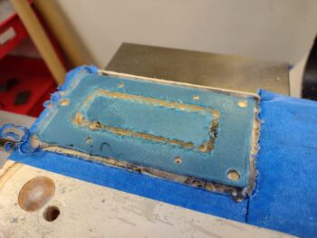
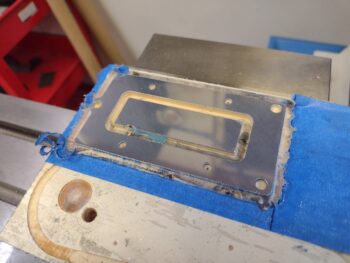
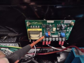
Here we have the encoder wires cut and pinned (pic 1) and then terminated into the 9-pin D-Sub connector, which is plugged into the Acorn CNC-12 board (pic 2).  The red ring terminal is the shielded wire ground.

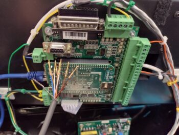
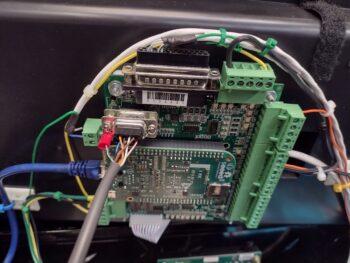
Notice the 2-post connector just to the left of the red ring terminal?  That is the Variable Frequency Drive (VFD) 0-10 volt output that controls spindle motors on much larger lathes and mills than most home shops have.  Most smaller hobby lathes and mills tend to use a 0-5 volt range to control spindle speed.  More on that in a minute…

With the spindle encoder now installed, I tested out its operational capability.  The good news is that it was spot-on and matched my external lathe RPM readout almost exactly as I cycled through RPM ranges by using the command line on the control screen.

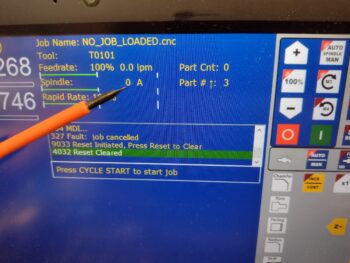
The bad news is that the RPMs I was asking for on the command line screen were not being accurately produced at the lathe spindle.  Again, the no-kidding spindle speed was being reported correctly by both the encoder and the external RPM display, but it wasn’t what I was telling the system to do.

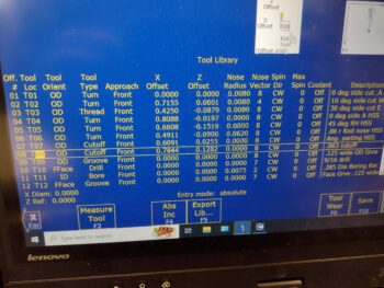
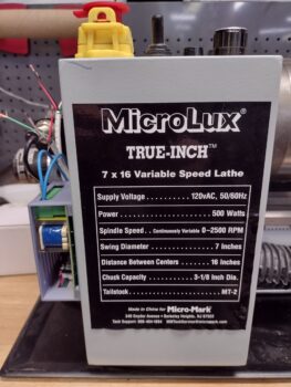
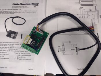
Remember the 0-10 volt VFD output from the Acorn board?  Well, for us home shop bubbas we tend to use a KBSI-240D signal isolator board to translate that 0-10 volt Acorn board output into a usable 0-5 voltage range to dictate lathe spindle speed.  Zero (0) volts translates to a stopped spindle.  5 volts is max RPM, which in the case of this lathe is 2500 rpm.

On the KBSI-240D are two (2) trimpots: one to dial in the max voltage, and the other to dial in the minimum voltage.  Taking voltage readouts while commanding various spindle RPMs has proven that the MAX trimpot ist kaput, TU, no muy bieno in that it won’t allow me to adjust the upper voltage down to 5 volts.  In fact, currently it’s stuck on a whopping 12.47 volts, which is clearly no good for this configuration.  Moreover, this sucker has been the hidden fly in the ointment over the last couple of weeks truly hindering my ability to get the spindle control dialed in.  It makes total sense now after finding it.

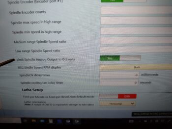
Now, a new feature in my new updated (note: not upgraded… yet) version 5.08 Acorn CNC software is that in the configuration is a menu item that allows the Acorn board to output 0-5 volts through the VFD port.  I thought this might be my get out of jail free card, but alas, it did not work either when I tried to hack the system.

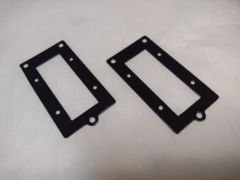
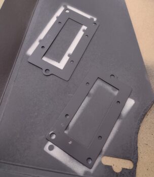
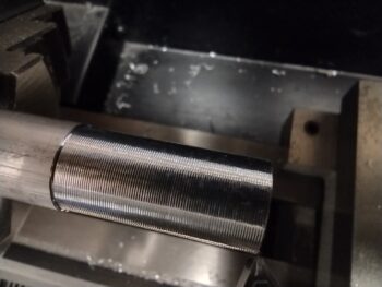
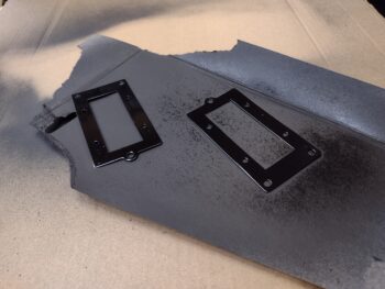
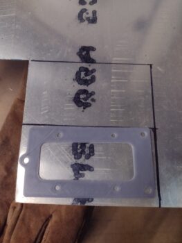
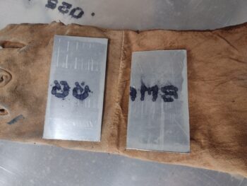
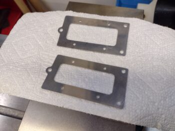
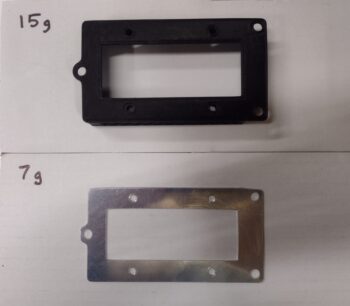
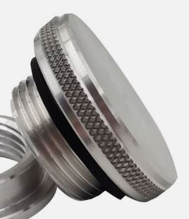
Thus, I pulled the KBSI-240D board and will do a final test on the MAX trimpot to see if it is truly bad.  If so, I’ll order a new trimpot and solder it in at some future point.  Since the lathe is currently spotty, I finally just pulled the trigger on some stainless steel rod, a M8-1.0 tap and 7mm drill bit to create my own stainless steel bungs for the compression style EGT fittings.  Ones that won’t be so bulky and heavy.

Yes, during the colder weather I did want to get my lathe CNC conversion completed and get it online.  I’m clearly much closer, but with the weather temps inching up as we move towards spring, I need to get back onto the no-kidding airplane build.


Chapter 3/19/22 – Lights & Lathe

Just a quick post showing that I finally got the wing light mounting brackets painted and clear coated without any further incident.  After the couple coats of clear coat cured, I then baked the light brackets in the oven at 175° F for 2 hours to harden up the paint as best possible.

I of course then worked most of the day on trying to get this lathe CNC finalized.  Currently I’m back on the spindle control piece of the puzzle since there are some squawks there that need to be fixed.

Chapter 3/19/22 – The struggle is real!

The struggle against the shop critters that is….

Case in point: I primed and painted my wing light mounting brackets last evening and left them to cure overnight, and had planned on clear coating them after this good 24-hour cure.  However, upon entering the shop I saw some type of footprints and very visible scratches on the surface of one of the brackets (note bottom of pic).

So I cleaned up the scratches and prints off the brackets and hit them with another couple rounds of paint.  Tomorrow I plan on clear coating them… hopefully without issue.

I then did another big round of cleaning up the shop.  Alas, the squirrels, et al, really did do a number on my shop while I was gone on my Christmas/New Years adventures… there was downed insulation panels, tufts of pink fiberglass and poop pellets everywhere.  From here on out I really have no choice but to remove their primary objective: the ceiling fiberglass insulation.  They love this stuff as they burrow their way into it, pissing and pooping the whole way… and then shred it so that it comes down in a myriad of pieces vs the complete whole panels that I installed.

I’ll again remind ya’ll that the combination of the persistent colder weather along with significantly much less insulation on the ceiling of my shop is hampering my ability to keep the shop warm for composite work.  Thus my current meanderings on other tasks.

Speaking of which: back on the lathe, I did some facing and touch-off cuts on some scrap aluminum stock as per the Centroid Acorn CNC-12 Lathe manual in order to set up my CNC-12 tool library.  Below is a cut I made with a carbide insert tool with a fairly shallow depth of cut and a somewhat rapid feed.  I think it looks kinda cool so I threw the pic in here.

And here is a shot of the screen as I add all the tools to the Acorn CNC-12 tool library.

I’ll note that my initial smattering of lathe tooling is fine for hacking my way through some manual lathe ops and some basic CNC, but not —as I’m learning— for any refined or optimized CNC lathe operations.  Thus, I do now have a decent amount of tooling on order and am awaiting those to arrive as I strive to get seriously online with my ability to use the lathe to make serious parts.

Pressing forward.

Chapter 3/19/22 – More Lathe Stuff

Today I continued pressing forward with the lathe CNC conversion by updating the Acorn CNC control software from version 4.64 to 5.08.

As I was writing out my task to-do list for the day, I got a call from my good buddy and fellow canardian Marco.  We of course discussed Long-EZs and projects, but we mainly discussed machining… specifically lathe CNC operations.  The call was perfect timing since I had a number of questions regarding employing CNC on a lathe, which is a much different animal (a more hybrid blend of CNC using less Fusion 360 CAM and a whole lot more Acorn CNC macros, or “canned” lathe cycles) than CNC on the mill.

When setting up an Acorn CNC control computer, it must be a dedicated CNC computer.  The Dell laptop I have has not been connected to the outside world via Internet in years, to keep Microsoft from sneaking in software that may crash a CNC program.  However, the catch-22 is that when new Acorn software is released, it is based on the current Microsoft .NET framework, with all the latest updates.  Thus, the first step in updating the Acorn lathe CNC software is to “briefly” connect the computer to the Internet and do a controlled Microsoft Windows update.  As you can imagine, this took multiple hours (pic below from later at night after new Acorn CNC software update to v. 5.08… note column of white buttons at left on gray panel: these are new pre-set lathe cycles that require simple parameters to be inputted before executing, an upgrade over the older software that didn’t have these pre-programmed macro/canned cycles).

While my dedicated CNC laptop was getting all the security and Microsoft .NET framework updates, I pulled down about a half dozen panels of pink fiberglass insulation that were clearly in use by unwanted intruders.  Yes, I may have won some battles, but the squirrels and giant field rats won the war.  The ceiling insulation is on its way out.  Currently my shop smells like a bathroom in an inner city bus station… the ever-present smell of squirrel piss wafting through the air.

I loaded my truck with a bunch of the nasty removed insulation panels and took them to the dump.  Upon my return —as the CNC computer slowly did its update thing— I did a good round of cleaning in the shop.

The good news is that the fewer the insulation panels, the less places for the rodents to invade and occupy.  And yes, I’ve tried traps, poison, ultrasonic blasters, barriers, etc. to keep them at bay.  The bad news?  Did I mention, it’s still cold??  So no major epoxy-based tasks until it warms up.

During yet another phase of my CNC computer update (it took about half the day), I cleaned up the inside corners of the wing leading edge light brackets, tested their fit on the actual lights, then cleaned up the brackets for a round of primer, then a couple of rounds of black paint.   I’ll clear coat them in the next day or two.

With the Acorn CNC dedicated computer finally updated with the latest round of Microsoft junk, I once again took it offline and locked it down.  I then proceeded to backup my old 4.64 software version (in case the new one crashes) and then updated my Acorn Lathe CNC software to version 5.08 (see pic above).  I then spent about 45 minutes updating the operating parameters in the software that is specific to my system (I took screenshots earlier of all these screens).

I’m happy to report that the lathe CNC software is updated, now back to getting it configured to make some chips!

Chapter 19/22 – Wing light brackets

Ok, folks… yes, I’ve been out of it for a bit.  As some of you may be well aware, we had a good little cold spell here.

During the cold weather I was digging in deep to get spun up to get my lathe CNC online.  I got a good ways before realizing that I need to upgrade my lathe software to do the CNC I need to do, so that will be another week or so.

Meanwhile, in needing to use my truck I had some issues with it that I needed to tend to, including installing both a new battery and alternator.  Moreover, I’m fairly certain that this last round of really cold weather was the straw that broke the camel’s back in regards to my well water pump dying.  Another near 2 days in sourcing a new one and getting that installed.

I would say that I’m ready to jump back into the Long-EZ build —which I am— but I’m heading out for a long weekend that I surprised Jess with, so I’ll be back on it for another day or two before heading out on another short trip, just for fun.  Next Monday I plan on digging back in hard core on the build (whew!).

As for today’s build shenanigans: a number of days ago I added a little meat around the edges of the wing leading edge light mounting bracket (in Fusion 360 CAD) … about 0.05″ each side for more space for the 3 mounting screws to secure it.  I then 3D printed a thin mockup of the new bracket version to allow me to use it more as a template for marking the aluminum stock for cutting.

Looking around the shop for exactly what stock I was going to use, I settled on 0.025″ thick 2024.  Here I’ve marked up the 2 pieces that I’ll machine to make up the wing light mounting brackets.

I then cut the 2024 pieces…

And did my favorite blue tape and super glue hack to secure them to a scrap 2×4 for milling (yep, you can’t take the Neanderthal out of a Neanderthal “machinist!”).

I then prepped and machined the first landing light mounting bracket …

then did the same thing for the second one.

Here we have the 0.025″ thick 2024 wing lights’ mounting brackets, after I cleaned them up just a bit.  In the next day or so (weather dependent) I’ll clean, prep and paint them.

My immediate goals are to finish up the aft lower engine baffling, and also get the stainless steel compression-style EGT probe mounting bungs trimmed down on the lathe (for weight) so I can get them welded into place and operational.  Over the next few weeks I’ll be working to finish up the engine stuff to get it finalized, including the firewall.  When the weather warms up enough to start slathering up the bird with micro to finish it in prep for paint, I want to be ready to get that ball rolling.

Chapter 3 – Lathe CNC spindle control

Today was one of those days where the amount of actual work accomplished was maybe 45 minutes while the amount of research and prep to do that work was half the day.  But I got ‘er!

Again, through a ton of research I was able to figure out the wiring to my just-installed Lathe CNC spindle control board (from Little Machine Shop).  This board, along with swapping out a chip on the lathe main control board, allows the CNC control software (I’m using Acorn CNC) to start and stop the lathe’s spindle, control the spindle/chuck RPM, and provide directional commands for either forward or reverse.  This comes in real handy not only during normal lathe ops, but especially during creating threads and tapping.

Here’s the lathe side wiring.

The main thing I needed to figure out inside the Lathe CNC control box was wiring up the two relays that control the forward/reverse direction of the spindle.  Here is that wiring.

The main issue I had when I went to test it was not any of the wiring I had just completed, but remembering how to use the darn software.  At first I thought my wiring was wrong but then I realized I wasn’t inputting the right commands… doh!  It’s just been so long working these functions in the Acorn CNC software.

That being said, when I did finally get it fired up, the control was spot on… and that 4″ chuck was very smooth, vibration-free and purred like a kitten.  I still have some final dialing in to do, so I’ll make a short video when it’s operational.

Again, after I do some test lathe ops on some scrap stock, I’ll be chucking up the compression EGT probes’ stainless steel mounting bungs to trim those suckers down a good bit to knock off some weight.  Those bungs are an excellent excuse —while the weather is still fairly chilly— to get the lathe up and running since I’ll need to use it to make a number of other airplane parts as well!

Chapter 3 – Tooling up: Lathe CNC

Today I continued my work to finally finish the CNC conversion on the lathe… it’s way overdue.  I’ll also again highlight that with the weather colder it’s a good time to do tool upgrades and implementation since big epoxy-based tasks are a non-starter currently due to low shop temperatures.

I’d say the primary hole in my plan for integrating this new CNC spindle control board into the lathe control system is analogous to my GRT rant a while back: documentation. While the install docs that came with the control board have the basic install covered, they don’t go into any detail on how it integrates with the CNC control system I have, so I will be diving deeper and making a few phone calls over the next 2-3 days.

Thus, the main goal today was to simply get the new CNC spindle control board, housed in its nifty 3D printed case, mounted to the side of the lathe’s electronics box.

The blue wires connect the CNC spindle control board to the lathe’s AC power mains.

I said the space was tight inside the lathe’s electronic box… too tight to mount the new CNC spindle control board inside there.  But even the connecting cable from the new externally-mounted board to the existing interior board takes up a ton of space.  It’s the big black cable that looks like an oval race track.

I then closed up and re-mounted the lathe’s electrical box.

I incorporated a reinforced hole on the side —in my design of the CNC spindle control board’s case— to allow for mounting a wire-securing Adel clamp.

As a reminder, here is the CAD model of the case I designed for this new control board.

A front view of the freshly mounted CNC spindle control board housed in its 3D printed case.  The front of the case is open to allow for installing the control board into the case, but also so that when the lathe cover is installed  . . .

… as it is here, then the end cover serves as the de facto front wall of the CNC spindle control board case.

Since I am clearly getting the lathe up to snuff to use it, I also pulled the 5″ chuck off the lathe to swap it out for a new 4″ chuck.  The 5″ chuck is simply to big and heavy, causing way too much vibration for this size lathe to handle.

Here is the new 4″ lathe chuck in the box… which I bought over 6 months ago?

And here is the new 4″ chuck installed on the lathe.

Inching closer to have the lathe ready for real world CNC ops!

Chapter 3/23 – Dipstick cap & Lathe

Well, between the still quite chilly weather, a good day and a half storm (causing a bunch of tornados inland that killed some folks), helping a friend using the trailer and knocking out a few other household tasks, I haven’t been as focused on the build over the past week as I want to be.

I’ll start off with reporting some good news.  I received the billet aluminum (or so it was advertised… it IS aluminum) threaded dipstick cap.  I immediately took it out to the shop and checked the fit: spot on!  It threaded in nice and smooth.

Here is the top face of the cap.  I’ll be drilling a 3/16″ hole in the center of this cap face to mount the dipstick rod.

This dipstick cap has an o-ring seal just like the Lycoming ones.  But unlike the Lycoming/Superior dipstick caps, this one is LOW profile to avoid clearance issues with the top cowling.

In other news:

I’ve also been doing some research to FINALLY finalize my lathe CNC conversion to allow me to get some parts made and tweaked (e.g. the EGT probe threaded mounting bungs).

I’ve had a kit from the Little Machine Shop in my possession for almost a year now that will convert my lathe to allow for the CNC system to control the lathe’s spindle speed and direction.  To do this, I have to add another board into the mix and tie it in to the existing electronics via a cable.

The first task in converting my lathe’s control board to allow adding in the new CNC control board was to swap out an integrated circuit (IC) chip one of the existing boards.  The removed original chip is in the Styrofoam block resting on the cables.

In addition, I needed to find a home for the added CNC control circuit board inside the lathe’s electronics housing.  The problem is that there is simply no room for this new board with how things are configured inside the housing.

After doing a good bit of measuring and assessing the setup, I decided to mount the new CNC control board outside of the electronics housing and simply run the cable in from outside.  It will be mounted to the left outside wall of the electronics housing under the left end spindle cover.

To minimize any dust or debris from dirtying up the new CNC control board, I designed up a protective box in Fusion 360 CAD.

I kicked off the 3+ hour 3D print on this new protective box, but about halfway through the ABS/polycarbonate filament I was using didn’t do well at all in printing out the box, so I switched to a standard ABS and restarted the print.   We’ll see how it turns out in the morning.

Since the weather over the next 6 weeks will most likely remain too cold for me to the major micro finishing on the remainder of the plane (unless we get a multiple day warm spell), I’m going to focus on all the other tasks —including cutting and mounting the firewall— that I can do until I can get to micro finishing.  Up next is still finishing the aft lower aluminum engine baffles.

Chapter 23 – Light brackets & oil pre-heater

I started off today by placing a strong LED light under the engine and searching for gaps in the CF inner baffles… I then slowly and carefully filled any gaps I found at the seams of the CF inner baffles.  With this task complete, it finalizes the install of the CF inner baffles.

Last night I worked a good bit on adding hexagons to the sides of the wing light mounting bracket…

Today, after finishing the gap sealing on the CF inner baffles, I then got back to work on finishing up the addition (in CAD) of the hexagon grids on the ends of the wing light mounting bracket.  The hexagon grids around the perimeter of the mounting bracket are not only for lessening the weight, but for air flow as well to aid in heat dissipation.

I then 3D printed the wing light mounting bracket.

Here we have a couple more shots of the wing light mounting bracket with the new hexagon grids added to each end.

I then test fitted the actual light unit into the wing light mounting bracket . . .

and it fit very nicely.

Now, with all that work done on the 3D printed wing light mounting bracket, there was one final check I needed to make: weight.  Here I checked the weight of the 3D printed wing light mounting bracket (15g) vs the 2024 aluminum wing light mounting bracket (7g).  Clearly the ABS mounting bracket is twice as heavy as the aluminum one, so my plan going forward is to stick with the aluminum wing landing light mounting bracket.

In other news, I received the oil sump mounted oil pre-heater from Anti-splat Aero to help heat up the engine on those cold flying days.

Here is the spot where I will mount it: the front right corner of the oil sump on the vertical sump wall.  This spot is right at the lower corner of the oil sump so the heater will “hover” just over the bottom of the oil pan, which will be a great configuration for heating the oil up.

I plan on running the electrical cord up over the top of the engine to allow me to gain access to the plug through the oil dipstick door.

Tomorrow I plan on jumping back on the aluminum engine baffles to get those knocked out.

Pressing forward!

Chapter 23 – CF baffles installed!

I started off today doing a good bit of research on my oil dipstick, to either buy one outright that would work or gather more info on making one myself.  In my research I stumbled upon a post on the VANs air force forum that contained information about a billet aluminum knurled oil dipstick cap with the thread size and pitch that I need (my old Lycoming dipstick won’t work since the thread size is incorrect for the new Superior oil level tube).

With this cap being WAY cheaper than buying a Lycoming or Superior dipstick outright, I went ahead and pulled the trigger on it.  Moreover, with its low profile design this oil dipstick cap already works much better in my configuration in regards to required clearance with the top cowl/oil check door than the taller stock caps.  I’ll assess this cap after it’s delivered to see if it will work for me (some mods required!)… I’m cautiously optimistic that this thing will fit the bill.

I then spent a good little bit of time aligning and drilling the through-hole in the cross shaped left inboard inter-cylinder baffle before adding a grommet and then installing it.  As I did on the right side, I also installed the 90° right angled tab using both glue and the 1/4″ bolt that secures the fuel injection distribution “spider” bracket.  Also note that I did the final install of the -4 fuel line to the fuel spider.

Knocking out these left side inter-cylinder baffle pieces finishes off the installation of all the CF inner baffles.  I will have some minor gap fill tasks to complete, but for the most part I’ll be heading back to finish off the aluminum baffle installs.

I then knocked out a task I’ve had on my to-do list for quite awhile: machining the wing leading edge light mounting bracket, or at least a test bracket to check out both its weight and functionality.  I’ll also remind everyone out there that these wing light installs are a prerequisite task to micro-finishing the wings.

Here is the freshly machined wing leading edge landing light mounting bracket which I milled out of some scrap 0.032″ thick 2024 (from the aluminum baffles).  The aluminum stock wasn’t a perfect specimen size-wise (a hair short in width and on height at one corner), but definitely close enough to provide a good working test bracket.

Here is the cleaned up newly machined wing leading edge light mounting bracket along with the previous 3D printed initial test bracket.

Finally, here is the machined wing leading edge light mounting bracket with an LED landing/wig-wag light test fitted into the bracket.

Tomorrow I plan on starting on the lower aft aluminum engine baffles.  I’ll also be working on finalizing the trimming and final configuration of the exhaust pipes as well.