Chapter 22 – Instrument Panel

Along with my recent acquisition of the Insight Strike Finder, I threw together a quick updated mockup of my instrument panel.  I realize it looks a little busy, and I think that’s at least due in part to both my Android phone (Left side of panel) and iPad Mini (Lower center panel) screens not showing aviation related info.  The Android phone will connect to the GRT system via Bluetooth and will display engine instrument data.  The iPad Mini will display an electronic flight book like Foreflight or FlyQ EFB.  Also, the switches are displayed with white strips of paper for spacing, when of course they will be mounted in normal fashion with standard aircraft style labels.

So, with that, here is the latest version of my instrument panel:

Chap 22 - Instrument Panel


Chapter 22 – Strike Finder

After reviewing my intended mission profile and realizing that using the Long-EZ’s range in traversing the US–meaning midwest thunderstorms–as well as flying up and down the mid-Atlantic region with its inherent summer thunderstorms, for safety and increased comfort factor I wanted some form of real-time lightning detection capability… above and beyond NEXRAD weather.  I researched out the various lightning detection systems, and decided that I would like to install either a Stormscope or an Insight Strike Finder.

Chap 22 - Strike Finder

I found an older Strike Finder on eBay and decided it was worth purchasing.  Although it was an older model, I had pre-coordinated with Insight Avionics to check out and upgrade the unit to an Ultra Bright LED display.  This upgrade replaces the face of the instrument so that not only is the display much more readable and reliable, but the the entire instrument face is brand new.

Chap 22 - Strike Finder Sensor

I was able to buy both the control head and the sensor unit (antenna) as well.  I shipped the control head and sensor off to Insight where they provided a sensor cable, and checked out the unit.  After the control head & sensor units checked out fine, the Insight techs upgraded the display to the Ultra Bright LED.

Here’s the actual unit (before upgrade) shown below:

Chap 22 - Strike FinderChap 22 - Strike Finder

Here’s a description of Strike Finder’s capabilities from the Aircraft Spruce site:

The STRIKE FINDER® Digital Weather Avoidance System detects and analyzes the electrical activity emanating from thunderstorms within a 200 nautical mile (nm) radius of the aircraft. A unique graphic display plots an accurate, reliable and easily-interpreted picture of electrical activity that you can use to circumnavigate the hazards associated with thunderstorms.

The STRIKE FINDER® System analyzes the individual strike signal properties to determine the bearing, range and severity of the activity. Strike data is plotted on the display as single orange dots by range and azimuth, in relation to the aircraft symbol (“heads up”). As the number of lightning strikes increase, so does the number of plotted strike dots. Cells start to form indicating increased lightning activity.


Chapter 22 – Trio Autopilot Servos

Avionics update.  Oddly enough, I have had the Trio Autopilot on my list for quite some time now as a January 2014 purchase.  Admittedly, I vacillated between buying the whole autopilot system or just buying the servos.  Specifically, I was looking at the Trio Pro Pilot, and to be clear, I put it on the “to-buy” before I knew I was going to spend a year in the Middle East for Uncle Sam… thus planning to be much further along in the build.

Now, I’m going to digress just a bit to elaborate on how I came to the decision to go with the Trio Pro Pilot Autopilot.  I had never heard of Trio before the Summer of 2012, when I was engaged in one of my many research sessions on Mike Beasley’s site.  On his panel, he had a cutout of the Trio EZ Pilot.  Being the curious type and intrigued as to Mike’s choice of autopilot, I did some research on a new found prospect.  After watching a couple of YouTube videos on the Pro Pilot–taking something to me that was shrouded somewhat in a cloud of mysticism and magic (i.e. autopilots) & making it look relatively simple–I was initially sold on the Pro Pilot.

That all being said however, I do TRY to approach my aircraft component selections somewhat clinically and empirically, so during my time in Tampa I set out to confirm my initial feel-good thoughts on the Trio Pro Pilot by contrasting and comparing to other autopilots.  The contest came down to the Trio Pro Pilot and the GRT “insta-” autopilot (just add servos!).

Now, there’s no doubt in my mind that GRT has a fantastic autopilot (cheaper and lighter too), but three things stood out in my mind for the Pro Pilot being just a cut above GRT’s autopilot:  1)  Redundancy.  GRT can easily run the Trio Pro Pilot, but at the same time, if my GRT EFIS fails, I still have an autopilot system that can be operated completely separate from my EFIS system.  2)  Ease of use.  Either the guys at Trio are true geniuses or just completely lucky, because IMO they absolutely nailed the interface and created an autopilot that is really darn easy to use (I think it’s both, but no doubt the Trio guys are geniuses… and great to work with!).  3)  Integration.  Lastly, since the Trio guys are EZ guys, there are clear-cut specific instructions on how to install these things into a Long-EZ, Cozy, etc.   No guess work or interpolating!

Ok, so back to my component purchase plan.  After pondering it a bit, I rearranged my purchasing plan and kicked the Trio Autopilot can down the road.  I figured all major electrical & avionics purchases should wait until I’m farther along in the build.  Besides, I still have one major purchase left for the engine: the cold air induction system from Sky Dynamics.  Thus, I demoted the Trio and moved up the cold air induction system and felt pretty good about holding to a prioritized plan.

Ahhh, but fate & irony always play into the story, eh.  In January, as I was spending some time perusing eBay for stuff, I ran across a guy who was selling his Trio Pro Pilot servos that he had picked up a few years ago for his Zodiac 601XL project.  His price was not that far below what a new set of servos would cost, so out of curiosity I inquired Chuck at Trio about any possible upgrades or mods that might be needed on some servos that were a few years old.  Chuck did confirm that there had indeed been some upgrades in the past few years, and that they would be happy to upgrade the servos to new specs if I purchased them.  Well, after doing some cost analysis, it just wasn’t worth getting the older servos.  So I let the servos go and moved on to other things.

Well, I noticed about a month later that, apparently, the gentleman selling the Trio servos wasn’t able to sell them and had them back on eBay for a much lower starting price.  Thus, armed with the knowledge and known cost for upgrading the servos to new specs from Chuck at Trio, I had a cost window to operate within for possibly getting the servos and saving a fair amount in the process.  Well, being a self-proclaimed eBay sniper I watched the auction for 6 days, and in the last 10 seconds there were 2 other guys that bid on it, but I was fortunate enough to win the bid.

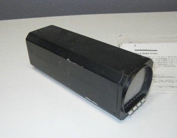
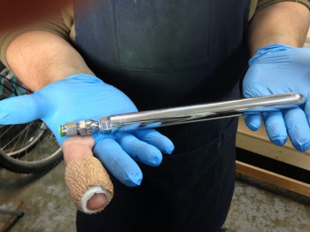
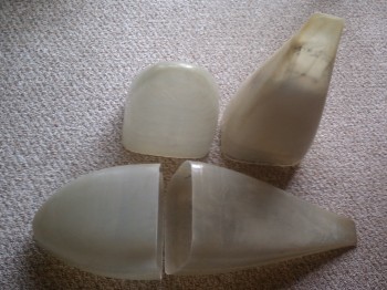
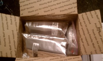
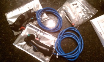
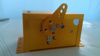
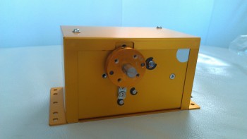
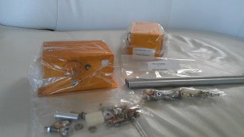
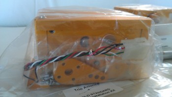
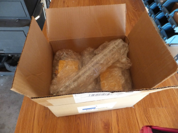
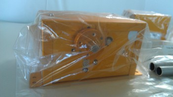
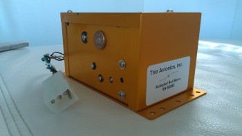
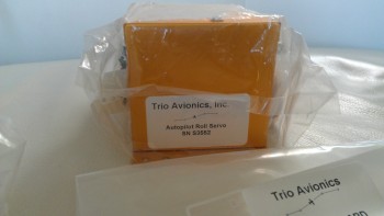
Having pre-coordinated with Chuck on my intentions, I had the seller send the servos straight to Chuck at Trio, where they checked them out, made a couple of upgrades to bring them up to new specs, and then function tested them to ensure they were A-OK operationally.  With the hundreds of dollars I saved on the servos, I had Chuck throw in a Trio Pro Pilot wiring harness and a few hardware pieces specifically for a Long-EZ install.  Below are some pics of my new Trio Pro Pilot Servos.

Chap 22 - Trio A/P Servo

Chap 22 - Trio A/P ServoChap 22 - Trio A/P ServosChap 22 - Trio A/P ServoChap 22 - Trio A/P Servo KitChap 22 - Trio A/P ServoChap 22 - Trio A/P ServoChap 22 - Trio A/P ServoI feel fortunate to have found these servos, and ironically stick to my original purchase plan, even though I had changed it.  I feel compelled to quote an old boss here as he defined “luck” as “when preparation meets opportunity.”

Chapter 22 – Instrument Panel

Over the past few months I’ve been going round and round on my Instrument Panel layout. I’ve researched a myriad of instruments & avionics, built matrices to compare various components–from clocks to autopilots–and am slowly getting a picture of WHAT components are going on the panel, maybe just not exactly WHERE the components will go on the panel.  Of course, since I’ve been working on my electrical system, current draw, integration, weight and cost have all been factors in the panel plan as well.

Moreover, a  lot of the panel layout will be based on ergonomics, which of course requires me actually sitting in the cockpit making airplane noises before I decide on my final configuration.

Still, I thought I would post a few pics (out of MANY) of my proposed panel options.

Chapter 22 - Instrument Panel LayoutChapter 22 - Instrument Panel LayoutChapter 22 - Instrument Panel LayoutChapter 22 - Instrument Panel Layout

Again, my panel is currently an ever-changing storyboard.  For the most part, the avionics and instruments are what I’m planning to go with presently, but as time moves on & new technologies and/or opportunities (e.g. the TruTrak ADI) present themselves the panel design can of course easily be updated.

Finally, one point of note.  My panel cutout is about 0.7″ shorter in height than my real panel, so in reality I have a little bit more wiggle room to play with when stuffing various electrowhizzies onto the panel . . .  if it all fits on my mock up.


Chapter 22 – Backup Attitude Indicator

Just an update on the continuing project planning & component acquisition efforts.  I have been spending a lot of time both on my electrical system & subsequently on my instrument panel.  As I get more research under my belt, gain a bit more knowledge, and figure things out, I then of course ask my building buddies what their plans are for whatever I’m currently carrying on about.

In one of the latter iterations of my planned instrument panel, my buddy Marco noted the myriad of redundant capabilities I had for simply displaying airspeed and altitude.  Of course I want SOME redundancy in my systems for backup purposes, but having 4-5 different ways to measure airspeed may be a bit overkill!  I hadn’t intentionally planned on having this many, just so many of the newer avionics these days have built in extras that may add more than we need if we go back and assess our actual requirements.

One of my primary culprits in this area was the TruTrak Gemini PFD.  It’s a great piece of technology and really has a lot packed into a nice, small package.  But when I went back and re-assessed my requirements, I had included it on my panel for one primary reason: as a backup attitude indicator.  I had accepted the fact that it provides airspeed and altitude information simply as a bonus.  But at what cost?  Cost here meaning actual money, since at 5.4 ounces it wasn’t necessarily breaking any feasible weight allowance thresholds.

So, in the vein of saving money and sticking to a prioritized plan to get this project in the air soonest, I decided to forgo the extra ASI & ALT features built into the Gemini PFD and focus on the primary capability I needed here, again, simply a solid backup attitude indicator.  In my ensuing research I found a TruTrak ADI for sale on Ebay for way below half the cost of a new Germini PFD (and well below the new touchscreen 3-1/8″ TruTrak ADI as well).  After a number of emails back and forth with the seller–who had just pulled it out of an RV-8 during a panel upgrade–I decided to pull the trigger.

Now, I will suffer about an 8 ounce weight penalty vs using the Gemini PFD/ADI, but for now I’ll simply put the Gemini PFD/ADI (or whatever future equivalent) in the “planned upgrades” category, to be purchased down the road after my bird is flying.  Swapping TruTrak for TruTrak will be a fairly easy upgrade both physically & electrically, but will of course require a new weight and balance . . . but most likely I’ll have a few more upgrades & modifications in the mix around that same timeframe, so I’m sure a new W&B will be in order regardless.

Thus, introducing the latest addition to the instrument panel:

Chap 22 - Trutrak ADI

TruTrak ADI (3-1/8″) Features:
– Gyro / VS pitch display
– Bank Angle display
– Built-in Ground Track DG (via built-in GPS)
– High Bank Angle Warning
– Low Airspeed Warning
– Slip/Skid ball


Chapter 22 – ADS-B Receiver

In looking back over my notes I failed to post this in the correct order.

So the plan right now is to definitely have full ADS-B by using the Trig S-mode Transponder and a capable ADS-B receiver to provide that capability.  I have to say that one thing I really like from the GRT folks is they tend to play nice with others, this means options.  On GRT’s page where they discuss the various ADS-B receivers that will integrate nicely with their EFIS systems, they provide some pretty good info.  Of course, I original set my sights on the Navworx ADS-600B, but after looking at & assessing my actual bottom line requirements I decided that if I am going to have enough funds available to get this bird in the air within the next 10 years, I better forego the almost $2600 receiver and get a little more pragmatic (my primary goals were to have an ADS-B receiver that would integrate with my Trig S-mode transponder, display weather & traffic data on both my EFIS display and iPad, and meet the FAA’s 2020 ADS-B requirements).

Enter Radenna’s SkyRadar ADS-B Receiver.  Although at first glance the SkyRadar seemed to be nothing more than a portable receiver, as I looked at it more and more it seemed to be a very capable receiver.  And, as with the many components I’m looking at or have bought, a number of the RV drivers give the SkyRadar enthusiastic thumbs ups. So, the SkyRadar went on the list as the most likely candidate that I would purchase in the future for my ADS-B receiver.

Chapter 22 - Skyradar-DX ADS-B Receiver

You may be asking, “What happened?”  Well, if the recent past tells you anything, then you’ll know that I’m cheap… and in being cheap I refer back to my oft cited mantra that sometimes you’ve got to spend money to save money!  Ok, the bottom line is I went to Radenna’s website to confirm some info on the SkyRadar-D, when lo & behold they had just come out with the SkyRadar-DX . . . which includes a built-in AHRS!  Moreover, they [are having] a sale where the first 50 buyers get $200 off the price that the SkyRadar-D normally sells for (the offer appears to still be going on!).  So, after a few hours of conformational research to ensure this was in fact the ADS-B receiver I wanted, I pulled the trigger.

So here’s the info on this device:

SkyRadar-DX Dual Band Receiver with Built-In AHRS

Key features:

  • SkyRadar-DX’s operating frequencies are 978MHz and 1090MHz and the latter conforms to DO-260 standard.
  • 5Hz GPS receiver
  • Artificial Horizon Information
  • Output data over Wi-Fi network (multiple displays can be connected)
  • Operates as Wi-Fi Access Point
  • USB high speed serial port output
  • Input voltage 11-36 volts
  • Power consumption less than 5 watts

The SkyRadar Receiver contains the following major components:

  • UAT receiver tuned to receive and process ADS-B data
  • High accuracy GPS module
  • WiFi module transmitting data to iPad, iPhone or iPod Touch

Chapter 22 – Flight Data Instrument

Well, since I’ve been researching out my avionics & instruments alongside my engine components, I’ve started scheduling out some purchases for some of the panel avionics that I know I’ll for sure be installing.  One such item I serendipitously stumbled across in my research is the Flight Data Systems AFP-30 Air-Data Fuel Computer.  This guy was developed by an RV driver to add some more data points that he wanted to see in his cockpit.  After researching this out and cross-referencing it in a matrix I have to compare all the functions of all possible avionics and instruments, I decided that this was definitely going on my instrument panel to provide me both unique & back-up instrument capabilities.

Chap 22 - Air-Data Fuel Computer

The AFP-30 performs functions in 3 main areas:

Air Data Computer

  • Altitude
  • Density Altitude
  • Indicated Airspeed
  • True Airspeed
  • Mach Number
  • Total Air Temperature
  • Saturated Air Temperature
  • Winds Aloft
  • Crosswind Component
  • Headwind Component

Fuel Flow Computer

  • Fuel Flow (Gallons/hour or Liters/Hour)
  • Fuel Used
  • Fuel Remaining
  • Fuel to GPS Waypoint
  • Fuel At GPS Waypoint
  • Range
  • Endurance
  • Fuel Efficiency (NMPG, MPG, MPL)

Performance Computer

  • Manifold Pressure
  • RPM
  • Percent Horsepower
  • Mach

Chap 22 - AFP-30 Air-Data Fuel Computer


Chapter 13 – Initial Nose Plans

Well, today I decided to act on yesterday’s vow to figure out my build plan for the Davenport extended nose.  I broke out the Davenport extended nose plans, figured out a myriad of details and made a template for my NG-30s.

One thing in specific I was looking at was the battery position & its installation configuration in relation to the heated pitot tube, and how it effected the capability of retracting the pitot tube.

Now, let me backtrack to February 2013.  I may have been a little remiss in the reporting of my project progress since I overlooked an extremely important component: my retractable heated pitot tube made for me by good friend Marco, a fellow Canardian and Long-EZ builder . . .

My Retractable Heated Pitot Tube

Yes, Marco–being the excellent & talented machinist that he is–machined me this beautiful retractable heated pitot tube.  Of course this wasn’t just a simple ‘throw some metal on the lathe and here it is’ endeavor, it took literally a couple months of research and discussion, and quite a bit of engineering and design.  And countless hours of machining work by Marco.  Marco describes the first part of the process here on his Blog What have I gotten myself into!

In addition, Marco covers the features of my Pitot Tube in this awesome video he made:


January 2013 – New Year, New Stuff!

I went ahead and just lumped all my acquired bounty into one post for the month of January.  Obviously, while I’m here in Tampa and my project is back in Germany, there’s not much building going on.  There is however, a whole lot of time to design my electrical system and other major end items, and actually think a bit on each component, have some lengthy discussions on them, and then make some purchases.

One such item was my wheel pants.  I was told by a few of the Old Guard that Sam James makes some great wheel pants.  So I caught up with him at an EAA breakfast in Ft. Meyers a few weeks after I ordered them and picked them up.  The wheel pants are sized for a 500×4 Lamb tire.  Again, trying to keep things light!

Chap 24 - Wheel PantsChap 24 - Wheel PantsChap 24 - Wheel Pants

I also took the opportunity while in Florida to pick up my canopy from Todd Silver in Ft. Lauderdale (there’s a lot of forts in Florida, eh?).  Another nice guy!

My Canopy

Chap 18 - Canopy

After a few discussions with JD Newman, I figured out all my buttons & switches (I think!) and then ordered my Infinity stick grips.  Very nice grips! And pre-wired too!

Chap 22 - Infinity Stick GripsChap 22 - Infinity Stick GripsI ordered a fairly new-to-the-market 2-speed trim controller from TCW which was made specifically for heavier duty trim actuator motors (read: NOT Ray Allen servos!).  Also nicely packaged and looks to be good quality.  I had a few long discussions with the TCW bubbas about their different products, and these are some pretty smart guys!

Chap 17 - Pitch Trim Controller (TCW)

Along with a new Starter Contactor, I also picked up a new Master Battery Contactor: the Gigavac GX-11SA.  Why?  Well again, in my discussions with the electrical gurus, I realized that to keep as light as possible in my build that I want to utilize B&C’s L40 40 Amp alternator, which is about as light as you can get in alternators (vs the vacuum pad designs).  Thus, I need to conserve amperage anywhere and everywhere I can.  The standard battery contactor takes about 1 Amp to keep the contactor closed and electrons flowing.  The Gigavac GX-11SA has a special internal circuit that once the contactor closes and the circuit is completed, it keeps the contactor closed for less than 1/10 of an amp (0.090 to be exact).  So, for the same contactor weight, I gain 0.9 of an amp.  Doesn’t seem like much, but when you only have 40 amps to play with, and a decent amount of “electro-whizzies” (as Bob Nuckolls calls them) that you’re using in the cockpit, you want (I want) as much spare power as possible.  (The pic below is not my actual Battery Contactor, but a representative one… just as I did for my starter contactor).

Gigavac GX-11 Master Battery Contactor

Is there a down side?  Yes, there is a slight bit more electrical noise, but according to Bob Nuckolls & Eric Jones, it’s negligible.  (The high efficient internal coil is shown at lower right in the diagram below).

Gigavac GX11 Contactor Wiring Scheme

Finally, below is a shot of my roll bar and my support down-tubes that will tie in the roll  bar to the base assembly.  I was originally going with a 0.1″ thick steel plate for the base that would travel from one longeron to the other, but that’s too heavy, especially if you add any cross support tubes to the mix (see my diagram with a couple square tubes under the steel plate).  So right now I’m looking at having one rectangular-tubed cross support and taking my vertical support down-tubes from the back of the roll bar straight to the rollover assembly side supports on the longerons to eliminate a second/rear cross tube (which is the way many people build it). This will further eliminate some weight.

Chap 8 - Rollover Bar & support struts