Chapter 13/22 – Parking brake installed

Crazy that it took me about 7 hours to get all this done… of course, I had planned on getting much more accomplished than I did.

First, I watched a couple of videos on Flaring tubing and also did a review of the Matco emergency brake specs and installation, including a good video on that as well.

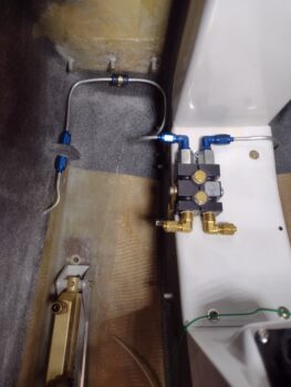
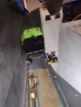
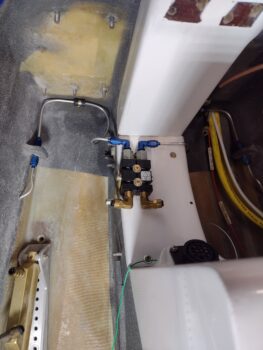
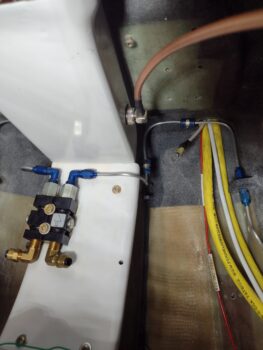
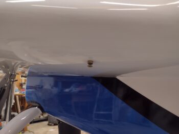
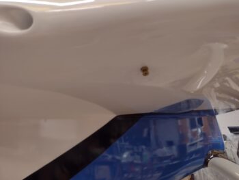
The flares on the right side brake tubing cross-connect, which I did after the left side, were much better than the left side’s.  Thus I cut a new length of tubing and remade the left side with much better flares.  I then did the final install of the left side aluminum tubing brake line cross-connect to the parking brake valve (pic 1).  I then did the final install on the right side brake line cross-connect as well (pic 2).

I then installed the Parking Brake engagement handle . . .

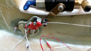
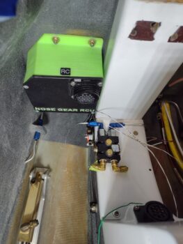
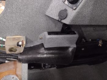
after I installed the parking brake ON indicator light microswitch (close up below).  After getting the handle cable installed at the correct engagement length in the parking brake valve lever, I did the final install of the Nose Gear RCU (Relay Control Unit) that was awaiting all the brake line cross-connect shenanigans to be complete to allow its installation.

Here’s an old closer-up shot of the microswitch that powers the panel “Parking Brake ON” LED indicator.

And another closer shot of the forward left NG-30/aft Napster bulkhead area.

And a video I shot 8 years ago showing the parking brake handle cable functioning:

Yep, slowing inching forward!

Chapter 13/22/25 – The Big Swap

Again, a 2-day post here . . .

Day 1 was the big swap.  I loaded up the canard this AM and with the “outboard wing” (now canard buffing) sawhorses that I reinforced with cross-bracing loaded up last night, delivered the canard to Phil’s shop.

I met Guy there where he helped me load up the right wing in the trailer, while we placed the top cowling in the back of his covered truck bed.  I also had the aft nose/avionics cover in my truck cab.

After delivering all that back to my shop…

we then loaded up the left wing in the trailer and the bottom cowling in his truck and delivered that to Phil’s shop.

Here we have the left wing in Phil’s shop.

And a wider view of the canard and left wing at Phil’s shop.

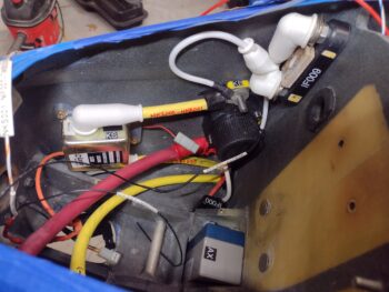
By late into the evening I had finished cutting and terminating the big yellow starter cable in the nose and installing it onto the bottom terminal of the starter contactor (anodized gold box center left of pic), which in turn has a big yellow cable that connects to the battery contactor (middle, black cylindrical).  I also mounted the ANL-40 inline fuse block and connected the B-lead from the alternator to it, and from it the cross-connect cable to the battery contactor.  All in the forward nose battery compartment, of course.

Day 2: Phil had some slight break-throughs on the canopy’s blue paint, so this morning I mixed up a small amount and took it to his shop and spent a couple of hours touching up those break-throughs.

Here we have Ray in the foreground working on the canard, with Phil behind him working on the left wing.  Behind Phil is the canopy, ready for its final buffout and ceramic coating after a minimum 24-hour paint cure.

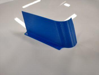
Back at the house I spent a couple of hours in CAD drawing up this seemingly simple protective cover (from fingers touching a potentially powered circuit) for the ANL-40 inline fuse.

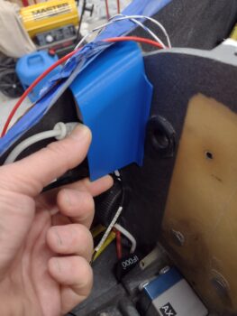
My dimensions must have been spot on since this is the first and only 3D print I did of the protective cover… here being test fitted into place.  I’ll probably Velcro it to the Napster bulkhead and call it good.

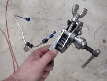
I then got busy fitting, cutting and flaring the 1/8″ 3003 aluminum tubing for the forward brake line cross-connects.  I had already made these before, but lost them either in moving down to NC or in the hurricane/tornado that hit my hangar back in 2019.

Here is the initial fitting of the 1/8″ 3003 aluminum tubing forward brake line cross-connects for the left side (pic 1) and the right side (pic 2).  I need to get the brake lines installed and square away before I start running wires aft of the Napster bulkhead.

Pressing forward!

Chapter 8/19 – Pilot headrest installed

The past couple of days have resulted in yet another couple significant milestones in that both the GIB seat cores and the pilot headrest are installed in the bird.

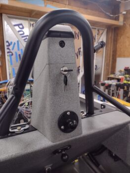
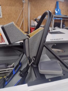
Here we have the pilot headrest no-kidding bolted in place on the pilot seatback, with the upper and lower headrest pads attached and the GNS-480 GPS antenna puck covered with a nice spiffy white radome.

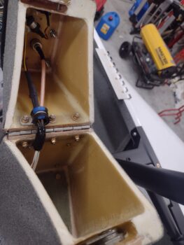
On the upper back side of the pilot headrest one can clearly see the “Big Brother” aft-facing wide-angle spy camera to keep tabs on any back seat suspe— er, ah, passenger!  And to have a good view of top cowling engine/prop stuff (hopefully never needed for that purpose!).

Here the pilot headrest is open for storage access (pic 1), where you can also the camera wires and GPS antenna cable (pic 2).

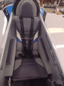
I officially finished off the back seat upholstery by installing the armrest pads (pic 1), where the right side will be most likely removed often (pic 2), to gain access to the decent-sized storage compartment under the pad, in the armrest (pic 3).

In prep for swapping the left wing out for the right wing at Phil’s shop tomorrow, I finished cutting and adding Thermo-Tec inside the wing root.  After the physical application of the Thermo-Tec was completed, I then used my gray hi-temp RTV to fill in the joints, seams and edges to avoid any dirt and oil from getting up underneath the Thermo-Tec.

And with that, I called it a night.  Lot’s of logistics going on tomorrow!

And, as always, pressing ahead!

Chapter 24/26 – Headrest pads installed

Another 2-day post here…

First off, here is a shot of the back seat area with the GIB headrest pad in place… honestly, I don’t remember if it was actually mounted or not.

But it definitely is mounted here below, as is the pilot headrest lower pad… both pads secured with #6 screws.

Also note the GNS-480 GPS antenna atop the pilot headrest is covered with a painted 2-ply fiberglass radome…. just to make it look snazzy.  Gotta have some fun with this stuff!

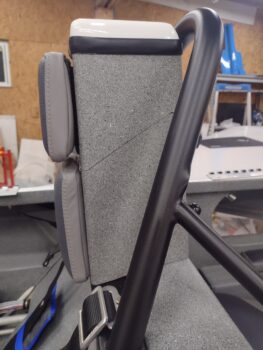
Here’s a side shot of the pilot headrest mounted lower pad.  It looks good secured to the surface with the aft side nice and flat.

I made a video on how I mounted these pads, which is something that would have been helpful to me when I was figuring out how to do it.

Lastly, here is a quick shot of the left rudder gust lock, painted, and a quick fit check.  The paint needs some cleanup, but besides that it is functional.

Again, pressing forward!

Chapter 8/21/26 – Hydramats & Rollbar

Today was yet another busy day just getting a bunch of tasks done to get this bird in the air ASAP.

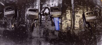
I started off by removing the tape from the just painted, labeled and clear-coated keys (pic 1).  I then separated them into pairs, added the labeled gas keys and put them on their respective rings: one primary set of keys with the red tag, and one backup set of keys (pic 2).  Keys are done… pressing forward!

My next task (later below) was actually shooting clearcoat on the rollbar… for clarity I grouped that together later on.

I did a good bit of painting and RTV/Permatex #2 work today because the next few days will be VERY cold… below freezing.

I taped up, mounted and degreased the CS spar bolt hole opening covers and the left rudder gust lock before shooting them with sealer first, then a couple of coats of white paint.  Not perfect at all, but will do the job.  Note that with the excess white paint in the cup, I taped and touched up a couple of the left vortilons to finish the touchups required on those.

Today was the day to knock out the installation of the Holley Hydramats in the GIB thigh support sump tanks.

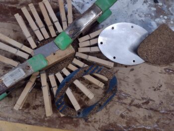
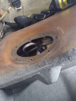
I started by cutting new full sized gaskets for the underside of each cover.  Versus the old oval “ring” style, I’ll note that a full gasket eliminates a possible exit point at the upper inside seam of the oval gasket.  After cleaning the underside of the cover with Acetone, I slathered Permatex #2 on both the gasket and the cover and clamped them together.  The bare cover and gasket to the right is the right side cover waiting to have its gasket attached.

I cleaned out each sump tank with Acetone, let it dry and then vacuumed it to get as much dust and debris out as possible.  I then installed the left tank Holley Hydramat.

And then the right tank Hydramat.

See what I call the “Madonna Bra” looking thing on the front wall of each thigh support sump tank?  I grabbed this shot to show this . . .

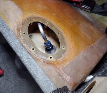
And then the inside of the sump tank.  That’s a low level fuel sensor that will ring off if the fuel ever drops below that level inside the sump tank.

Here we have both Holley Hydramats installed inside their respective left and right sump tanks, and the covers and gaskets secured in place, with all the excess Permatex #2 that I slathered on the edges removed and cleaned up.

Again, here we have my FIRST task of the day, but I forgot to grab a pic of the roll bar until much later, with other components in the shot.  Easier to just report on it here.

First, here is the 2K matte clearcoat that I dropped a pretty little penny on this morning at NAPA.

It did a great job in giving the roll bar a nice black sheen, but not too shiny as to blind the GIB when the sun hits it.  Note the white painted stuff you saw earlier, but also to the left is the pilot headrest with shot bags on top of the white painted “radome” that covers the GNS-480 GPS puck . . .

Which I installed with new, longer stainless steel screws that I also picked up on my quick shopping run this AM.  I actually did the initial drilling and screw-setting on the perimeter seal last night, but today I trimmed it so that the GPS puck was not on the seal edge, but firmly mounted and touching the ground plane.

The final install of the seal, which is a shape turned sideways (90°), has RTV on both the top interface and along the side edges of the headrest.

I then RTV’d the top side of the rubber seam and popped the radome into place.  After cleaning up the excess RTV, I weighed the radome down with shot bags and tightly taped around the seal perimeter (shown in pic above).  Tomorrow, after cure, I’ll of course remove the tape and shot bags.

I checked the tech sheet on my matte clear coat and it states that it dries extremely fast.  With that info I proceeded to mount the upper seatbelts and then install the roll bar.  In hindsight, I’m wishing I would have waited 24 hours since I had a few spots that showed the paint/clearcoat was still a bit too soft.

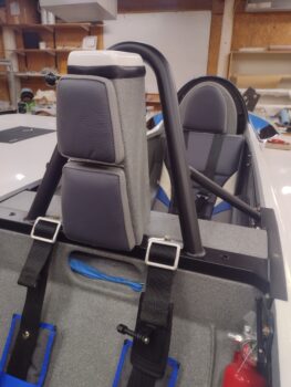
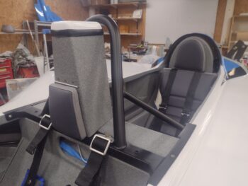
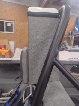
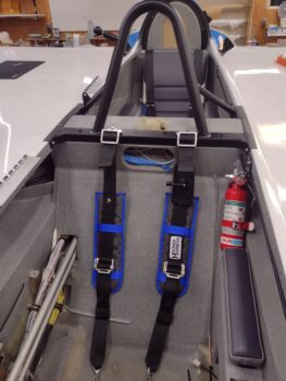
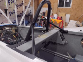
Regardless, the roll bar with the upper seatbelts attached is installed (pic 1).

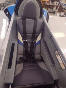
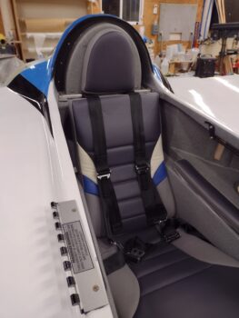
Now, before I installed the roll bar I actually installed the GIB armrests and then did the “final” install of the GIB seat cushions… meaning I pulled the wax paper off the Velcro strips and no kidding set them in place and then sat on them for about 15 minutes to set the Velcro adhesives as best possible (pic 2).

One last shot of the final install of the roll bar.

Yep, slowly moving out on this beast to get ‘er in the air!

Chapter 21/22/25 – Paint ‘n stuff

I started off today adding a bit more filler around the edges of the Ram ball mounts on the roll bar and sanding that before hitting it with a final primer coat before painting it flat black.

I also sanded down and hit the keys with primer as well.

A bit later I shot the keys with black paint and let them flash for about 45 minutes before carefully adding the labels to the keys.  Once the labels were in place, I then shot the keys with a few rounds of satin clear coat.

In between the rounds of paint, I marked and removed the GIB lower right side kickplate to allow me to cut the cable access hole in the top a bit bigger to allow for the cable cover that I then installed, for both sets of wires in this area (pic 1).  I also replaced the previous cable cover to the wires inside the CS spar opening (pic 2).

Although I didn’t get to it tonight, I removed the screws and covers off the GIB thigh support sump tanks in prep for installing the Holly Hydromats inside the tanks.  I plan to get to those tomorrow.

I also dabbled a bit on the pilot headrest/storage compartment by setting the GNS-480 GPS puck in its final position and drilling out the screw holes.  I then added aluminum tape to the top of the headrest as a ground plane for the GPS antenna.

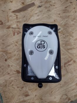
Here we have the GPS antenna in position on its ground plane (technically the ground plane is supposed to be a bit bigger, but this is all it gets!).

And with that, I called it a night.  Pressing forward!

Chapter 8/23 – Another milestone…

Today I was able to knock out yet another milestone: welding.

As of right now, after my visit to a local welder I am —to my current knowledge— done with welding on this bird.

Now, to back up just a bit, I’m going to invoke my oft-cited mantra: It’s better to be lucky than good.  A couple weeks back Guy Williams asked me to help assess a broken arm on the soft top of his convertible car.  After some discussion, I told him that I would look for others having that issue on any online forums.  He did, and then found a good local welder through a fellow EAA’er.

Well, after his glowing report of the welder at our last EAA meeting, I decided it was time to get my exhaust pipe bracket seams welded up… versus relying solely on my ugly tack welds to keep them cobbled together!

Here’s the result of that welding effort.  And after I got back to the shop I cleaned up the inside of each exhaust pipe cradle.

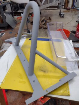
I also spent a good little bit of time last night and this morning to prep 3 attachments that I wanted welded onto the roll bar (here, after I shot it with 2 coats of primer).  You can actually see all 3 accoutrements in this pic below: A RAM ball mount threaded insert on the left aft side (just above the support arm), a RAM ball mount nub on the upper right side, and a lanyard tie-off loop on the lower right side support arm.

Here’s another look at the roll bar after I shot 2 coats of primer.

Here’s a closer look at the attachments that I had welded onto the roll bar:  On the aft left upright I had Noah weld a 1/4-20 threaded circular insert to allow attaching a RAM ball mount for a video camera, etc. (pic 1).  On the forward side of the upper right upright I had an NPT nub welded on to accept another RAM ball mount, that will be mounted permanently.  This mount will also serve as my headset holder when I’m parked (pic 2).

The last accoutrement that I added to the roll bar was a simple lanyard loop, that I fashioned by bending a 16-penny nail, that Noah welded to the aft bottom side of the right support arm.

Specifically, this will be used to attach a lanyard to secure the canopy air strut block to ensure it doesn’t run off or get lost somewhere… my canopy is a very large canopy and any time its open, it needs this block in place.

Tomorrow, I plan on painting and clear coating the roll bar and pressing forward in my GIB area configurations and installations.

Chapter 18/24 – CS spar hole cover

Another 2-day blog entry here.

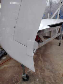
First off, here is the left winglet aft lower cover protective cap that I glassed with 2 plies of BID.  I still need to do the right side.

I taped cardboard underneath on both sides of the winglet to mimic the foam padding I’ll have on the inside of the cover.  I don’t really care if it falls off when hit, I just want it super light and the initial impact for both impactor and impactee to be as least injurious as possible, for both parties involved.

While Phil is doing a great job on my bird buffing out my combat paint job, he has been suffering from some major back issues, with definite surgery in his future.  Not surprisingly, between that and his assistant being gone way longer for the Thanksgiving break —delayed a week due to snowstorms— the buffing out of my painted components is at a crawl.  I was expecting to have all parts back mid-December and be turning and burning with installs to get this bird airborne shortly after.
That’s not happening.

The bright side of all this is that tasks I was going to kick off until after the bird was flying, I’m now “pre-loading” and getting them off the docket.

Today’s task is a perfect example: a cover for the CS spar center hole to keep the GIB upper seat pad from sinking into it.  I don’t know how other builders have their seat pads situated, but my GIB top seat core top edge ends right at the top of the CS spar.  The big access hole in the CS spar makes it so the seat pad top “falls into” the open hole and deforms the seat pad.

To fix this issue, I planned to cover both openings in the GIB seat bulkhead, both the bottom round one and the CS spar access hole.  The bottom one is complete, and many moons ago I glassed the lower edge, or catch, of this cover that wrapped around the transition lip at the bottom of the CS spar access hole opening… think inverted “U” shape: (or rounded “V” really).

Today I cut 2 plies of carbon fiber to add the actual hole filling part of the cover.  The layup was a bit tricky because it attaches to the AFT side (inside the CS spar) of the bottom transition lip catch.  I prepregged the 2 plies of carbon fiber, laid that up, THEN constructed and taped into place the foam board to fill the access hole.

Here we have the CS spar access hole cover 2-ply carbon fiber layup, peel plied and curing (pic 1).  And then later after cure (fast hardener) with the peel ply pulled (pic 2).

Here is the taped in place foam board used as the layup back wall support.  To tape the foam board in place on the inside I had a small oval cutout in the center to get my hand inside the CS spar.  I then taped the oval cutout into place along with the rest of the foam board.

A few hours later I pulled the 2-ply CF cover out and cleaned up the edges a bit.  Here we have both front (pic 1) and aft (pic 2) sides showing.

Since I was in a rush during the time I created this form mid-layup, I didn’t get any pics of it going in.  So here is an idea of the center access port (pic 1) I created to get inside and tape the perimeter of the foam board (which itself was cut at the same dimensions of the CS spar access hole except along the bottom).  I then cut out the foam board but left the perimeter tape for the final front side layup (pic 2).

Here we have the CS spar access hole cover trimmed and sanded in prep for the final layup:  A center core of Lantor Soric wetted out, with edges micro’d for a smooth transition, the small gap along the bottom catch and aft wall filled with dry micro, then a single ply of CF over the top of all that.

After laying up the final ply of carbon fiber and peel plying it, I then set the CS spar hole cover back into place and taped the perimeter to keep it in its final position as it cured.

As the cover layup cured, I sanded the epoxy wiped left rudder gust lock and hit it with 2 coats of primer.  I also want to label my assorted aircraft keys, so yesterday I Dremeled off the raised manufacturer’s mark on one side and micro’d the surface.  Today I sanded those down and epoxy wiped them for upcoming paint, labeling, and clear coating.  Finally, I taped up 2 of the left vortilons before touching up the black paint stripes on those.

A few hours later, after nearly fully cured (fast hardener again), I pulled the CS spar cover out of the bird and set it on this heated table (heat lamps below it keep it quite toasty).

A couple of hours later, I pulled the peel ply off the CS spar access hole cover, razor trimmed the excess carbon fiber and hit the edges quickly with a sanding block.

And voila! Here it is, ready for action.

My last official task of the evening was the final install of the canopy latch handle.  All these years I’ve been using the AN screw-head bolts that I love so much, but for the final install I switched to no-kidding AN3 bolts.  And since the threaded holes are different depths, I have at least 2 lengths of bolts in the mix.

And the requisite outside shot of the handle.  Looking good!

My generalized goal at this point, besides ensuring the left wing is ready to go to Phil’s shop for its paint tweaking, is to get the back seat area squared away before moving physically forward on electrical and component installs in the nose, panel and pilot area.

Pressing forward!
Chapter 18/25 – Right N number on

I didn’t get that much done on the bird the last couple of days, with the cold weather and getting some Christmas shopping done.

I finally got down to the one place left in the county to get some Kerosene for the heaters.

After filling and firing up a heater I then got to work doing a quick layup on the left winglet aft bottom corner cap that will keep me and any other unsuspecting victim from hitting that sharp corner.  Plus it will protect the corner, as I’ve noted my right winglet aft bottom corner has already been hit at Phil’s shop, by who I don’t know, but it’s not as sharp as it was and it has bit of paint off of it.  Exactly the purpose of this little cover: to protect both people and winglet … sorry, I forgot to grab a pic.

I then spent nearly 3 hours cleaning and organizing the shop, emphasis on organizing. Primarily focusing on tools and hardware.

I was able to scrounge up another four (4) MS21042-3 nuts, which I soaked in vinegar for about 30 minutes and hit them with a brush to clean/brighten them up a bit.  Tomorrow I will order another bunch of them.

I used the revitalized MS21042-3 nuts to install the forward canopy latch rod and hooks in the pilot seat area.  That being said, I left the aft of these 2 hooks installed with a temporary nut to confirm the best thickness of the washer between the hook and longeron in interfacing with the canopy.

The next morning I got a call from Phil, who wasn’t going to be in the shop due to some major back issues he’s having.  But he did let me in long enough to knock out putting on the right winglet’s N number.

I used the top of the winglet as my W.L. “zero” level reference by taping a yardstick to it, then measured down from it to get a somewhat straight line for the N number.  I then taped the N number in place in prep for applying it.

I’ve given up on trying to get anything perfect on this plane, since curves and all its varying angles will make just about anything look off… especially given from what reference angle you look at it.  Same applies with this number.

Moreover, I’ll note that even though I wanted the N number centered front to aft, in checking with the DAR they stated the most important thing to them was for it to not be on any control surface.  So I scooched it as close to the front rudder edge as I could get it as centered as possible (I know some builders put the number on the lower winglet, but I wanted it higher).

Placement aside, I think it looks pretty damn spiffy, especially considering that I ordered these numbers long before I was certain on my color scheme. Hoo-ah!

Back at the house I made a number of phone calls re. the bird and did a good bit of research the rest of the day, interspersed with holiday festivities prep…. still inching forward! (smile)
Chapter 8/18/24/26 – Bits ‘n pieces

After my last full night of work (my last blog post) I finally caught the flu bug that both my wife and stepson battled through.  I thought I had dodged a bullet, but it hit me like a freight train that night, and throughout most of the next day and night (yesterday).  I slept a ton, feel much better now and am back at it.

I’m guessing there will be a lot more of these somewhat disparate reportings in the next week or so until I finally get to the point of primarily focusing on final electronics/ avionics, fuel system final checks/flushing and engine install/first start prep.  I guess final flight control rigging will be in that mix as well . . . yes, still a good bit to do (sigh).

First off, my last blog post was incomplete, as I failed to report the gooping up (with Permatex #2) of threads and final install of the strake fuel tanks drains.  Here those are:

Today I started out by removing the peel ply and cleaning up the left wing outboard trailing edge fence.  I then marked it for trim, and after removing all the tape from the wing, set it back in place.

I’ll note that I had a few layup/micro tasks on my to-do list, but after my shop heater ran out of my final on-hand kerosene supply, I had to dump any tasks that required a warmer environment as the shop temp was low-to-mid 50s.

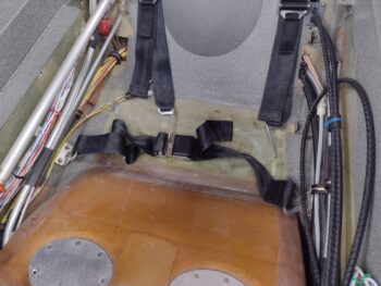
I did get the GIB lower seatbelts installed using the hardware ID’d in the plans.

I also took a surprisingly longer amount of time than expected to get the GIB right sidewall kickplate installed, as it was being finicky going in (some slight sanding required for final install).

On the left side it took me longer to find the correct hardware than it did the few minutes to install the GIB throttle quadrant and throttle/mixture cable protective cover.  Task complete.

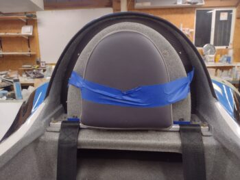
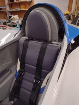
Still in the GIB realm, I quickly mounted the D-deck front cover, then taped the GIB headrest pad to that to ensure my mounting location for the pad to cover is good. Note the dark blue tape at the bottom which was my original guess of where the bottom of the headrest pad had to be at or above to clear that seatbelt upper strap crossbar (which I did in the house, confirmed in the shop).

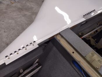
I also installed both the front and aft bottom canopy hinges.

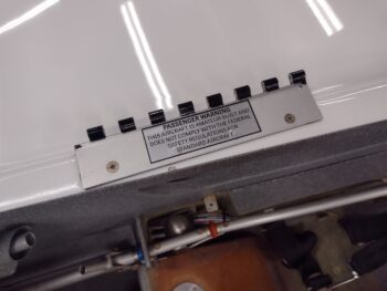
A couple comments on the canopy aft bottom hinge:

First, I applied the FAA mandatory passenger warning in pretty much the same spot that Mike Beasley did his on the canopy’s aft lower hinge plate, although I liked his sticker better but couldn’t find it (silver letters with black background).

Second, I’ll note that I used my cordless hammer drill to drive the hinge screws while I secured the nuts with a wrench on the bottom side of the longeron.  I had one screw that had jacked up threads, which caused my drill to jump and take a good ding out of the longeron paint —I of course had everything protected but this minor edge… go figure!  No big deal… just add it to the paint touch-up list (queue another dramatic sigh).
I then got to work on installing the canopy latch rod and hooks down the left longeron.  Besides pushing my 2100 rendezvous to have dinner with my wife, I also came to horrific realization (at first determination) that I have burned through nearly my entire stock of MS21042-3 aircraft grade nuts.  How?!  Who knows.  I guess I needed way more than I expected to finalize all the installs on this bird.

. . . or more likely there is a full bag of them hiding somewhere in my shop.  Regardless, I got the GIB side of the canopy rods & hooks to final install.

And since I couldn’t finish off the forward side canopy rod & hooks, in an act of sheer and utter defiance, I installed the fire extinguisher… with its requisite bracket of course (take that!! whoever!!!)

Ok . . . still nugging it all out.  One step at a time.