Chapter 23 – Final engine turning!

For the record, today was yet another 100° day in the shop… but who’s counting!

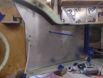
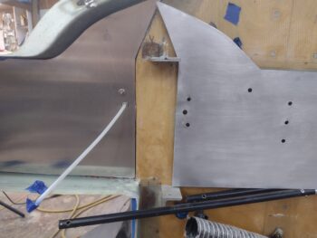
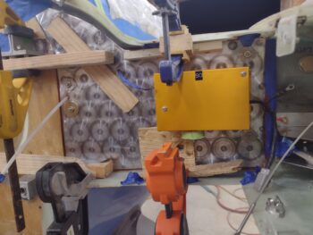
I started the day off by engine turning the left side CS spar and shoulder 6061 aluminum overlay.

I then put it in place to see how it looked and grab this pic.

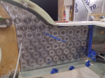
I needed to use some of the clamps and hardware from the right side, so I went ahead and removed all that stuff to reveal the mounted right side CS spar/shoulder aluminum overlay.

Not my best engine turning effort, since I was using a new disc and was having some initial issues with the pressure and it “biting” into the aluminum, but hey, this will be somewhat buried behind the engine and normally under cowl, so I’m calling it good.

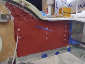
As I did on the right side above, on the left I completely covered the Fiberfrax and Thermo-Tec with a thin layer of red RTV.  Since the Thermo-Tec is slightly thinner than the Fiberfrax, I put a few thicker dollops of RTV on that small wedge area.

Then, using a 1/8″ notched trowel I applied the red RTV to the front face of the aluminum overlay . . .

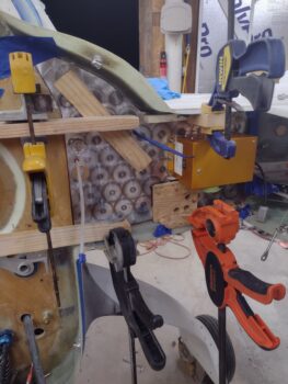
and then pressed it into place onto the Fiberfrax and Thermo-Tec.  I only have 3 Clickbonds on the left side, so I used 2 lengths of angled aluminum held in place with wide washers to press the middle area of the overlay firmly against the Fiberfrax, along with the other perimeter wood pieces clamped into place to also keep the overlay secured.

Of course my payment for the entire task above was being drenched in sweat from head to toe, so I took a quick dip in the pool to cool down.

After changing clothes, I got back to work for a couple hours wet sanding all the areas I had epoxy wiped after either some aggressive sanding, micro-filled holes or pinholes that needed epoxy filling: strake leading edges, upper fuselage/nose sidewalls and the upper side of the nose.

I’ll note that the right sidewall just under the canard is going to need another round of micro, since it’s got a few distinct and offending low spots.  It was getting a little later in the evening, and Jess had made a tasty dinner, so I called it a night.

Tomorrow my plan is to knock out the majority of creating the forward heat shields in both wing roots, which will require making up cardboard templates, importing those into CAD, and testing my templates before plasma cutting/bending them.  Also, I’ll need to layup some tabs for platenuts inside each wing root in order to secure the forward heat shields, so it will take a least 2 days for the forward wing root heat shields task to be completed.
Chapter 23 – CS spar overlays

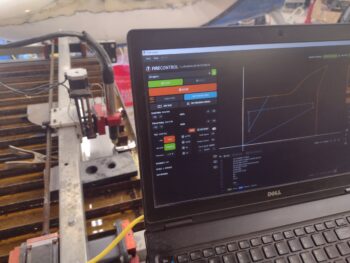
Last night I prepped my plasma cutter and plasma cutting table to allow me to start cutting metal parts.  I had a little bit of a hiccup with my configuration since I had used my plasma cutter off the table and needed to do some digging in the manual to get the cabling correct.

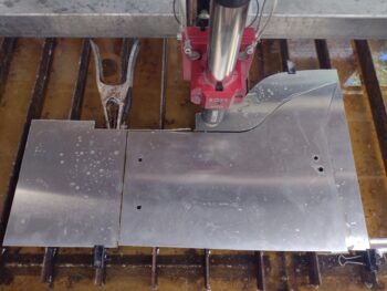
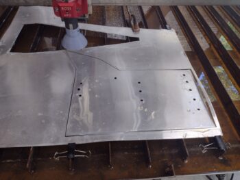
Once I got it all cabled up correctly, I then set up to plasma cut the right CS spar “wing” and shoulder overlay out of a 0.02″ thick sheet of 6061.

Here’s the result of that plasma cutting job.

At this point in the day my house AC parts were delivered, so I spent the next couple of hours installing those.  Thankfully it appears to have resolved the issue, and my house AC is once again up and running.  We’ll see how long it takes to get the in-house temp back to normal from the current 95°.

I then test fitted the right CS spar overlay, which after some minor tweaks fit very well.

I then set up to plasma cut the left CS spar overlay out of a 0.032″ thick piece of 6061 aluminum.

And here is the freshly cut out left CS spar and shoulder aluminum overlay.

I then test fit the left CS spar/shoulder aluminum overlay, and it fit a treat.  Note the finish on this piece of aluminum, which is pretty good.

However, the right side overlay had water spots and blemishes on the face of it that would not come off with Simple Green, Acetone or white vinegar.  I then tried wet sanding it up to 2500 grit sandpaper before buffing it out… unfortunately it still looked like crap.

Now, my preference —and plan— with these CS spar overlays was to simply cut them, clean them and then mount them.

But I just didn’t want to install an overlay that had some very visible blemishes, so I bit the bullet (and spent 30 minutes looking for my sanding disk) and engine turned the right CS spar/shoulder aluminum overlay.

I then put it in place to grab this shot to show how the engine turning looks before installing it.

I then removed the overlay and slathered up the Fiberfrax and Thermo-Tec shoulder with red hi-temp RTV.

I then applied red hi-temp RTV to the aluminum overlay with a notched trowel (I was rushing, so no pic) and then attached the overlay to the Fiberfrax/Thermo-Tec on the right side.

I temp installed the autopilot roll servo along with wide washers onto all the Clickbonds.  I also clamped pieces of wood in various spots with wedges to keep the aluminum overlay firmly pressed into place while it cured.

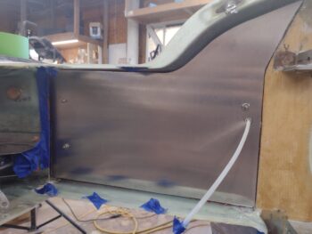
Here’s another shot of the installed right CS spar/shoulder aluminum overlay.

Tomorrow the plan is to engine turn the left side aluminum overlay and get it installed, after which I’ll start working on the forward wing root forward heat shields.

Yep, pressing forward… just not as fast as I’d like.

Chapter 23 – Engine bay heat shields

After taping up the Clickbonds, wire cable and rudder conduits, I started out today by slathering up the mating surface of each Fiberfrax piece with red hi-temp RTV and attaching them to the aft face of the CS spar on each side of the firewall, which I also used a small notched trowel to apply the red RTV.

The left side (pic 1) got a little messier than the right side because I had lot more pieces to fit into place, and with my RTV curing on a seemingly accelerated exponential scale due to the shop temp, I had to get these pieces attached post haste.

Yes, not your typical 70° degree shop temp… nope, today was yet another 100° plus day in the shop.

With the Fiberfrax in place over the exposed CS spar areas, I then cut and applied some Thermo-Tec hi-temp shielding to the shoulder areas on the top side, each side.

With my Thermo-Tec supply out and in-hand, I decided to do a few hour detour on a task that I had not yet fully committed on mentally, but decided it was a GO today: applying Thermo-Tec to the inside face of each inboard wing rib.

In my research/final check on how to apply Fiberfrax to the firewall, etc. not surprisingly I read a few horror stories re. engine fires. I figure anything that adds very little weight yet provides precious minutes or even seconds of flight time in the event of an engine fire is worth getting done.  And now was the time to do it.

So I used painters tape on the inside of the left wing to make up a template.

Which I then removed and took inside my lovely HOT house (AC parts due in tomorrow!).

And imported the template into Fusion 360 CAD.

I then again used my plasma cutting table as a plotter and made a line drawing of my inboard wing rib template on thick paper.

After a few iterations inside the wing, I had refined my left side inside wing rib template configuration.

Which I then used as a pattern to cut out a piece of Thermo-Tec heat shield.

I pulled the backing off the Thermo-Tec to expose the adhesive and carefully fitted it into place.

Here’s another shot of the internal left wing rib vertical wall covered with Thermo-Tec high-temp (up to 2000°) heat shielding.

I then flipped the left side paper template over and made a few minor tweaks to match the right side inside wing rib.

And again used that as a pattern to cut out the Thermo-Tec heat shield…

Which I once again pulled the adhesive backing off and carefully applied it to the inside vertical wall of the right wing rib.

I then spent a good hour getting my plasma cutter and cutting table prepped to cut metal, which I will undertake tomorrow to cut the left and right CS spar “wing” aluminum overlays to protect the Fiberfrax heat shielding.  After the CS spar “wing” heat shields are completed, I will then get to work on the forward wing root heat shields, one per each side.

Chapter 23 – More spar “wings”

So today was yet another ungodly hot day.  I spent about 2 hours working on my house outside AC unit, then another 45 minutes inside researching parts before pulling the trigger on those.  I bought a new capacitor and contactor, which I believe should do the trick.  I also ID’d a new fan motor to buy if it turns out to be that.

Back in my 100°+ F shop, I thought I had more 1/8″ Fiberfrax than I apparently do… so I played the “where might it be?” game for a good half hour, again in that blazing hot workshop.

Alas, I finally accepted that I only have enough to cover the actual spar proper on each side, with one full piece of Fiberfrax on the right side…

And barely enough actual Fiberfrax to cobble together a patchwork of pieces for the left side (sorry for the pic quality).

I had planned on attaching the Fiberfrax to the CS spar on each respective side TONIGHT but wanted to do a little bit more research on how to actually attach it.

I know some builders have used 3M 77 adhesive spray to attach the Fiberfrax to the spar and/or firewall, then in turn used the red high temp RTV for attaching the metal overlay onto the Fiberfrax.  Other builders use the red RTV for all attachments.

In looking at CP 82, buried on page 11, it notes to use the red RTV for attaching Fiberfrax to the firewall, CS spar, etc., so I’ll go that route… tomorrow.

Needless to say, I’m not exactly thrilled with this crazy hot weather… the multiple shirt changes and added shower or two more per day is just getting ridiculous.  Since after 30 minutes of work I’m drenched literally from head to toe with sweat.

Still… pressing forward.

Chapter 23/25 – Shop heat wave

So the heat wave continues… I said to myself at around 3pm that I should grab a pic of thermometer in my shop.  It was at about 104° at that point, and dropped a few degrees when I finally got around to grabbing this shot at 5:30pm.

In addition, the capacitor on my outdoor house AC unit gave up the ghost, so I’m in the process of locating one to buy.  My indoor house temp “only” hit a “cool” 95° compared to the shop (thank God Jess’s AC is working!!).

Regardless of the heat, I need to get this bird done.  I aimed the floor fans towards the front of the plane and finished sanding the re-micro’d areas on the nose, sidewall, strake LE’s, etc.

I then epoxy wiped the sanding scratches and pinholes with a couple coats.  The two biggest issues in completing that task was first containing the simply profuse amount of sweat from dripping onto the surfaces that I was applying the West epoxy to.  Since I had the West pump already in the 205 fast hardener, I pressed forward… thus issue #2 was anything more than a half pump of epoxy resulted in getting VERY close to exotherms with the internal shop heat being so high… needless to say it was probably the quickest, sloppiest epoxy wiping session I’ve done on this bird.

But I got ‘er done… all with about a 20 minute gap between coats because it was curing so darn fast!

Earlier in the day I had tweaked my left and right CS spar “wing” templates in CAD, and mid-evening tonight I again plotted them out using my plasma cutting table.  The final fit on these were much better so I’m calling these templates good and will be pressing forward with using them to cut the Fiberfrax as well as cutting out the aluminum sheet overlays to cover the Fiberfrax on each side.

Yes, the forecast shows we’ve still got a lot of days upcoming that will be hot as hades, but the build must go on!

Chapter 23 – CS spar “wings”

Over the past few days I have been able to finish up sanding all the epoxy wiped areas I finished nearly 2 months ago.  Not to brag, but that’s quite a decent little feat given the average shop temps have been well in the 90’s, with the heat index way above 100° F (I’ve also been helping local Canardian Guy Williams on stuff with his Long-EZ).

Here we have a the right side of the fuselage and nose adorned with pencil marks to be used as my ‘poor man’s sanding guide.’ (pic 1).  And after some aggressive sanding with both the new Jitterbug pad sander and the 30″ longboard I finally had to admit defeat in this area and apply another round of micro/West 410 to the low spots (pic 2).

I slathered quite a number of small divots and major pin holes all around the recently sanded epoxy-wiped areas with micro, including the nose as well.  I suspect on the nose and upper sidewalls that I’ll finish off the finalized micro with another round or two of epoxy wipes to clean up the scratches and any pinholes.

Back near the firewall, I used painters tape to create a template for the left CS spar “wing” (outrigger, exposed area… whatever the term) to allow me to transfer it into Fusion 360 CAD.

Which I did next for both left and right side CS spar “wing” areas.  My focus is on these to knock out first, which in turn will allow me to finish off the wing root forward heat shield on each side.

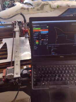
Although I grabbed this pic well after 9pm, the shop temp was in the mid 90’s (note fan). Here I’m once again using the plasma cutting table as a plotter to gin up some thick paper templates for the left and right CS spar “wings” on each side of the firewall.

I’ll note that there’s a way to edit the G-code that inputs a pause after each hole circle is drawn to allow me to lift the Sharpie to keep the line from being drawn between holes, obviously making the final diagram much cleaner.  But since these are merely temporary templates, I didn’t take (waste IMO) the time to modify the G-code and simply pressed forward.

Here are the plotted and cut-out left and right CS spar “wing” templates in place, with minor tweaks required for both… which I’ll knock out tomorrow.  I’ll note these templates will be used for cutting the Fiberfrax that will get Hi-temp RTV’d into place.  Then, with the CAD drawings dialed in, I’ll use those to plasma cut the thin aluminum coverings to protect the Fiberfrax.

Heat be damned!  Pressing forward!

Chapter 25 – Back to Finish

With my having been crazy busy over the past 6 or so weeks as I focused on Jess and mine’s wedding (and subsequent honeymoon), this post covers a smattering of tidbits back from the very beginning of May.

First up, here we have the floxed and glassed Clickbonds on the right outboard corner where the CS spar meets the inboard right wing root.  These Clickbonds will secure the front lip of the forward wing root heat shield that will also serve to keep hot engine compartment air/cooling air from flowing down this interface channel betwixt wing and CS spar.

Also from early May is the completed install of the Clickbonds on the left side of the CS spar for the same purpose:

To gain access to do the work above, I had removed the engine and had it hanging on the engine hoist.  To ensure the hydraulic cylinder didn’t bleed down over time, I secured a 2×4 to the cylinder with tie-down straps to ensure that the hoist arm wouldn’t lower over time, to avoid my engine ending up on the shop floor.

Over a couple of weeks the engine did drop a little, but I chalked that up to hoist flange merely biting into the wood a little bit more.  As another week passed, I then found something even a bit more insidious going on: the 2×4 was acting as a fulcrum, the engine was lower by a good bit more, and the wheels of the engine hoist on the opposite end were off the ground by a good 2-3″ (pic 1).

To solve this weird engine-hoist predicament, a few weeks into May I merely transferred the engine back onto the rolling engine stand and called it good… pic 2 (with more components now on the front [accessory case] of the motor I had to plasma cut some notches in the steel engine mount frame that was pre-mounted on the rolling engine stand).

I will also note that at the end of April my “little” buddy came over a few different days and really helped me in removing nearly everything out of the 2 far bays, blowing off and wiping all the micro dust off —again: everything— before it coming back into the shop.  We got both bays 2 and 3 cleaned out very well, but alas, Bay 1 (long work table and machining tools) is still dusty and cluttered.

I don’t have any pics, but last week I spent a few good hours sanding down the epoxy wiped micro fills on the aft ends of the aft wheel pants, as well as the epoxy wiped micro on the front half wheel pants… that was a good workout by itself.

Fast forward to this past week, where my main focus is finalizing the sanding of all the epoxy wiped areas that I never got a chance to sand, and prepping the exposed CS spar “wings” inside the engine compartment for a ply of Fiberfrax to then be covered by aluminum as a protective overlay to the Fiberfrax (firewall will be Titanium).

I took my previous foamboard template for the right side and reinstalled it with the new Clickbonds in place that will secure the forward wing root heat shield (pic 1).  I also removed the autopilot roll servo cable Deutsch connector (not without some drilling out of the inside click-in-place tab that would not come out without a fight).  This will allow me to slide the cable through a hole in the protective aluminum fiberfrax covering (pic 2).

I then got to work sanding.  A few months ago my issue was the persistent cold weather we were having, and now that my schedule has allowed me to go back to work on the plane the current weather is VERY hot.  And my shop AC is inop at the moment (a few calls to AC repair shops that said they don’t work on split systems).  The heat index is currently well over a hundred, but after doing some nitnoy prep tasks I finally bought an extra shop fan, bit the bullet and dove into about 4-5 hours of sanding per day the last few days: first on the epoxy wiped right and left strake leading edges, and then down the left longeron and fuselage sidewall.

Next came the fuselage sidewalls in the area around and under the canard, as well as the aft nose substructure.  As you can see in pic 1, I’m trying out a new air-driven “Jitterbug” pad sander that is working out quite well.  Still a ton of sanding required with even that, with a lot of excess cured epoxy coming off the surfaces (as seen on the plastic in pic 2).

My last task of the evening was the initial sanding to knock down the epoxy wiped upper nose.

After hitting it with the Jitterbug I then did a good amount of block sanding by hand to get it cleaned up fairly well.

I found a few major pin holes and minor divots throughout my recent sanding adventures, and the nose was no exception.  I’ll fill these with some West 410 compound and then sand the surfaces to final contour before calling them good for primer and paint.

Officially back at it… and pressing forward!

Chapter 25 – Wrapping up micro-finish

As I am getting into domestication mode in prepping my house for a ton of guests for my upcoming nuptials, I have been trying to continue to get key tasks done on the bird build as well.

I knocked down and final sanded the added micro on the both sides of the aft wheel pant tails.  I then epoxy wiped the new micro with a couple coats of West epoxy.

Although no pic, when I epoxy wiped the aft wheel pants above, I also hit the strakes lower leading edge micro fills (after final sanding) with epoxy wipes.

On the glassed spots on the inside of the aft nose cover, I razor trimmed and pulled peel ply on the previously delammed bare wood inside surface (pic 1), and did the same with a little edge cleanup on the front left corner layup (pic 2).

My goal was to get both side CS spar Clickbonds floxed/glassed in place, but it got too late too fast, so I only nugged out the final/top Clickbond on the left side.  Again, this is to secure the left wing root forward heat shield.

I plan on knocking out the pair of Clickbonds on the right side in the next day or two.

Although it took a few rounds, my final significant task was the epoxy wiping of the forward sidewalls, the avionics bay/aft nose substructure, the top forward nose, and the nose hatch perimeter lip, obviously on both sides.

And here’s a better shot of the epoxy wiped nose and nose hatch perimeter lip… again, from both sides.

My next major task will be to sand/wet sand all the epoxy wiped surfaces I’ve done over the past few days.  As I finish up the final fit and integration of the aft nose/avionics cover in relation to the canopy front skirt, I am starting in on the CS spar “outrigger/ wings” and the wing root forward heat shields, to be completed before the wings come off and flipped to finalize the micro finishing on each of those.  Since I don’t really want the firewall installed before paint, its cutting and install will come a bit later.

Still pressing forward… just in slow-mo for the next month!

Chapter 25 – Plodding to Finish

I started out today using the Fein saw to trim the overhanging glass that I laid up on the aft top (not glare shield) edge of the aft nose/avionics cover, at the seam with the front edge of the canopy skirt.  I then sanded the glass smooth to match the underlying vertical micro/foam.

I then flipped the aft nose/avionics cover over and did 2 layups: one on the left inside “flap” or “wing” that wraps around the nose over towards the fuselage side.  I discovered a delam here and cut out all the offending glass, and am laying up a single ply of BID to cover the bare wood underneath (Pic 1: And yes, we’re allowed to have would in/on these planes, but we have to cover it all in fiberglass to pretend it doesn’t exist… like a bastard sibling! haha).

I also needed to do another layup on the inside of the front left corner, and then added a very small dollop of flox at the edge to allow shaping this corner to fill in the gap better between it and the canard leading edge (pic 2).

I used Pro-Set epoxy for the layups above, and when done —not surprisingly— I had a decent little bit left in my cup.  I normally use fast hardener, so to be able to casually do an entire subsequent new layup from scratch is a nice break.  Here I’ve glassed the first (lower) of the two Clickbonds on the left side CS spar that will secure the left wing root forward heat shield… which will also serve to close the gap at the opening of the channel down the length of the wing and CS spar (hot engine compartment air = no good).

I had planned on starting my task below on the left side, but with my impromptu glassing-in of the lower Clickbond, I pressed forward on the right side.  I first made up a tape template, transferred that to foamboard and then pressed it into place over the numerous Clickbonds poking out.

Over the next day or few I plan on using this foamboard template to cut the underlying piece of Fiberfrax, and also as a template in CAD to plasma cut a thin piece of overlying aluminum (the firewall will be titanium).

Pressing forward!

Chapter 19/25 – Finishing end near?

After adding another round of micro around the nose-side perimeter edge of the nose hatch door, today I started off spending well over an hour fine-tuning the sanding on the micro lip.  I’m considering the nose micro around the nose hatch door complete, with a caveat that minor tweaks may be required as I prime and paint these components.

On the added lower mounting Clickbond for the right rudder cable bracket, I pulled the tape and peel ply and cleaned up the layup and threads (pic 1).  I then test mounted the right rudder cable bracket to check out the threaded mounting studs (Clickbonds) on the CS spar (pic 2)… all good.

After sanding the epoxy wipes on the aft wheel pants, I discovered that there were very slight, but noticeable (especially after paint) bumps where the glass from securing the two pant halves together were rearing their ugly heads (pic 1).  These layups are from me widening the Sam James VANs wheel pants to better fit around the Long-EZ gear leg, brake and wheel (ala Wayne Hicks).  Thus, another round of micro was required on the aft end, each side, of both wheel pants (pic 2).

I had a rough patch on each strake lower leading edge that when I micro’d the aft wheel pants above, I also hit those spots on the strakes as well.  I fully expect those to be the very last of the fills on the strakes, and after sanding I will epoxy wipe the leading edge of the strakes with 2-3 coats.

I sanded down the front wheel pants and took a bit more off on the rounded nose area, on each pant, more then I was expecting too.  With these good bit of sanding breakthroughs back into raw micro, I wanted to fill some voids and re-protect the pant noses… so I epoxy wiped them again with a couple rounds of epoxy.

With the engine off, I then got to work on the wing roots.  Here on the left you can see I trimmed and sanded the left wing’s aft heat shield platenut tabs.

Over on the right wing root, I grabbed a “before” pic with the tabs marked for trimming (pic 1).  And an “after” pic with the tabs cut and sanded (pic 2).

My last job of the evening was to lay up a hard edge on the lip of the Aft nose/avionics cover where it intersects the canopy.  For whatever reason it is way low in comparison, and instead of job globbing on micro, I added a 6-ply 3/8″ wide lip to create a harder edge which I will then finish contouring in micro.  Here it is a few hours later after it was mostly cured.

I realize in my recent banterings on what I need to finish I left out the aft nose/avionics cover… yes, I have a few final micro finish steps I need to do on this as well.

A reminder that tomorrow is my last full day of work on the build until June.  I’ll probably post about every 3-4 days since I’m limiting myself to only 1-2 hours a day on the build.