Chapter 22 – Electrons vs labels

This post covers a smidgen of my efforts over the last couple of days.  My overall goal at this point is to get the Tri-Paragon as prepped and pre-wired as possible before it gets mounted into the plane.

Besides cleaning it and blowing out all the nooks and crannies with compressed air, I realized that I was a bit premature in mounting the relay deck plate onto the top shelf, given that I just didn’t have the access to get in to wire up the AG6s, etc. so off with the top shelf and associated components.

I’m pretty much going through every component, connector and wire to again ensure that the Tri-Paragon is as prepped, clean and optimized as possible to get mounted into the bird.  Lord knows there’s an insane amount of wires hanging off this thing, and then add that to the insane amount of wires currently inside the bird?!  I need to be focused on connecting everything up, not fixing or redoing something that I could have caught on the bench.

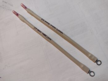
One thing I did was I went through all the wiring diagrams and inventoried the total amount and types of Fuse Links I needed.  The final tally was two 22 AWG fuse links: one off the Master Bus connecting stud for the ALT FLD (B&C voltage regulator) circuit breaker lead and the other off the E-Bus connecting stud for the P-Mag circuit breaker.

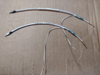
With my alarm inputs paired down to 5 per AG6 to allow me an audio alarm out to the audio mixer, I worked up those two single-wire shielded cables and finalized those connections.

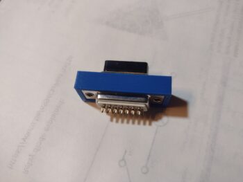
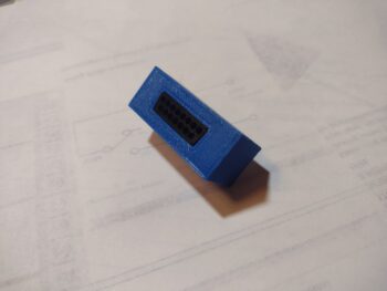
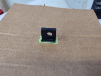
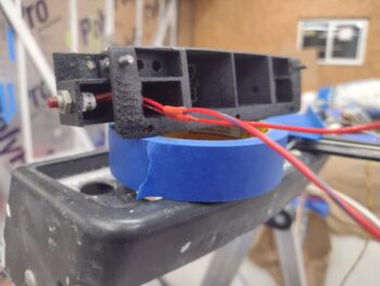
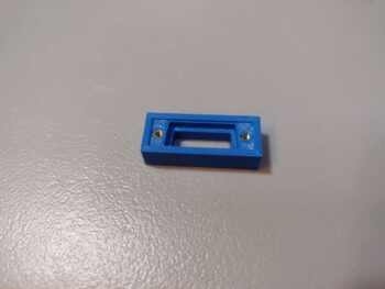
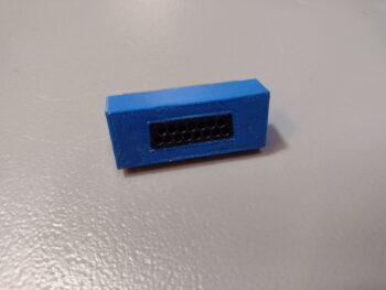
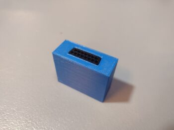
I also took a few moments here and there to work on my new G7 ground bus, where I did a quick measuring of the screw holes in the 15-pin D-Sub connector and transferred those over to the mounting bracket CAD model.  I then 3D printed out this test top section of the mounting bracket and used a special-tipped soldering iron to heat sink some 4-40 brass threaded inserts into the plastic (common practice in the 3D printing world).

I then test fit the male and female DB15 connectors into the bracket top test piece and secured them with screws into the brass inserts.  Yes, these are 3/4″ long screws, so I’ll need to pick up some 1/2″ long to finalize the assembly of this.

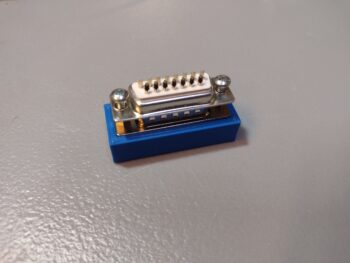
Here’s the front/top view after the screws were threaded in place.

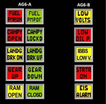
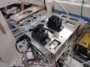
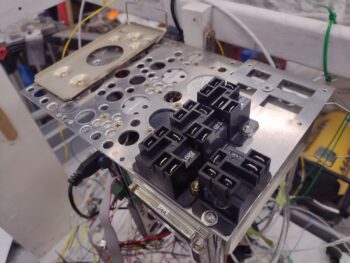
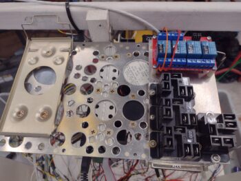
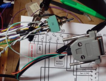
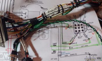
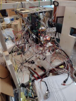
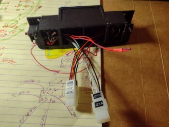
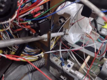
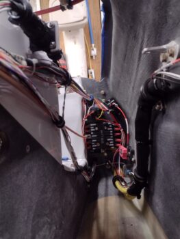
After my G7 ground bus mounting bracket shenanigans, I got back to work on the seemingly endless amount of wires, connectors and components on the Tri-Paragon. I have both AG6s wired for power, ground, dimmer and audio, with 3 of the 5 inputs wired up on the right side AG6-B.  The other input wires are physically in the aircraft.

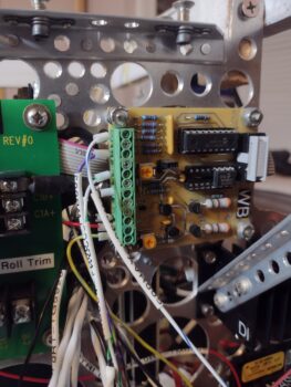
I only have 1 of the 5 inputs on the left side AG6-A wired up, so I didn’t feel inspired to grab a pic of that (note the Roll Trim relay board on the left side of pic above: that will get wired up once the Tri-Paragon is mounted in the plane).

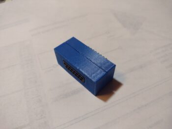
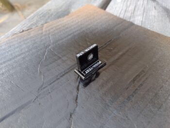
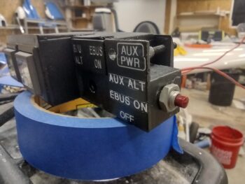
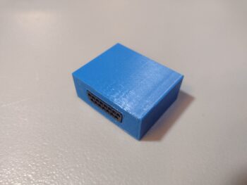
After a few more hours working on the Tri-Paragon, including at least 15 new wire labels applied, I spent about 5 minutes in CAD to increase the height of the G7 ground bus mounting bracket body, and then kicked off the 45 minute print.

Here is the result of that…

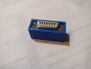
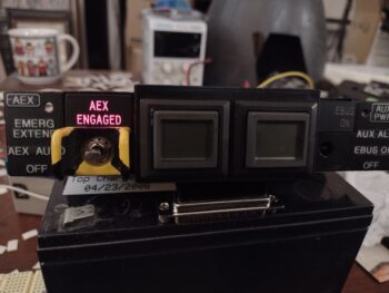
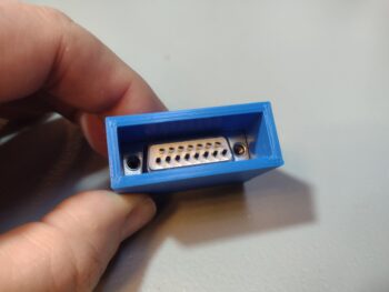
And shots with the DB15 D-Sub connectors in place:

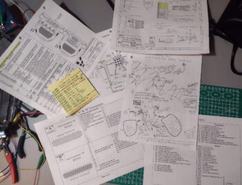
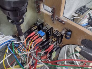
A good bit of what I am doing is simply verifying that the current configuration is, in fact, current so that the physical component installs, wiring and labeling all match… after all these years and countless modifications, changes and updates.  I’ll provide two quick examples to emphasize what I’m discussing:

Case #1:  On the wires exiting relay #9 —which controls the switching of PTT, headphones, etc. between COM1 and COM2— I had two wires labeled with masking tape: one “COM 2 PTT Pin 7” and the other “COM 2 Pin 14.”  There is only one glaring issue with these labels, neither of those pins are required on the Trig TY-91 com radio.

Perhaps I got them confused with the GNS-480?  Which I had originally designated as COM2… but it has multiple connectors (aka “plugs”) on it that are all preceded by “P” as in P1, P5, etc.  So it wasn’t that.  I then looked up my old wiring diagrams on my computer… nothing.

Clearly these wires didn’t match my current wiring diagram.  After pondering for a bit, I remembered I had considered using the MicroAir M760-REM as my COM2 radio.  After finding the manual on the GRT website under “Legacy Docs” I found the culprits.  I was then able to finalize the conversion (8-10 years later?) from the way old COM2 radio connections to the “new” Trig COM2 radio.

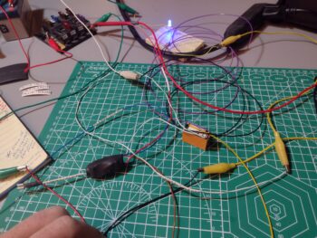
Case #2: I also focused on wiring up the dimmer (1 of 2) connector that is used by the AG6s, TruTrak ADI, etc.  While working in the rats nest of wires on the right side of the Tri-Paragon, where the dimmer connector is located, I happened across a gray wire with a red stripe.  The label denoted it was from the HXr to be wired to the dimmer I was working on.

Excellent! Another wire terminated and off the to-do list I thought.  So I trimmed the wire to length, stripped it and was just getting ready to crimp a D-Sub pin onto it when I thought, “I better double check the connector pin-out diagram for this.”

Sure enough, no HXr dimmer connection existed on any diagram, nor on my connector pin-out page.  But it WAS clearly labeled.  So I did another 10 minutes of investigating to find that I did have this HXr dimmer connection at one point, but nixed it since I had no space and needed a pin to hook up the avionics panel ammeter located in the nose. So out that wire came to make room for the Ammeter #2 wire to get inserted (that wire is also currently in the bird patiently awaiting to be connected!).

I am really beginning to wonder if it would have been better to simply wire everything up all at the end of the build!

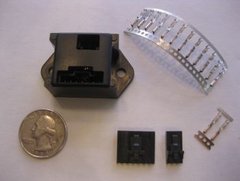
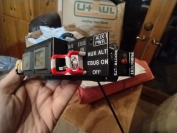
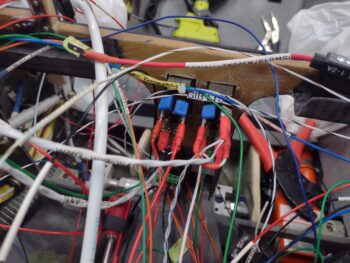
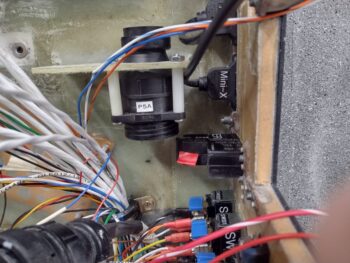
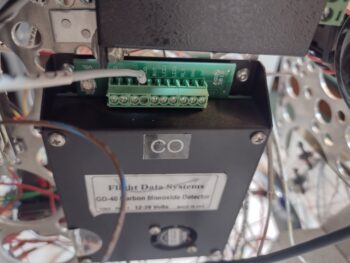
Speaking of wiring!  Another target for finalizing its wire connections before the Tri-Paragon is installed into the bird is the Carbon Monoxide warning sensor (Flight Data Systems GD-40).  I must say that verifying the wiring in the manual completely reinforced my decision to pull this input off the AG6.  The audio warnings out on this unit is actually quite impressive with a caution message first, then a warning message and also an all clear notification.

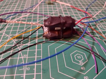
All the capabilities are fine and dandy, but we of course need to connect this CO Detector to the audio mixer, so yet another single-conduit shielded wire to gin up for that specific purpose.

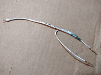
And here is that audio wire terminated in the GD-40 CO detector.

Tomorrow I plan to finish off terminating the remaining wires as well for the GD-40 CO Detector.  I’m hoping that by the end of the day tomorrow I will be ready to no-kidding haul the Tri-Paragon out to the shop and install it into the bird.

Pressing forward… albeit slowly!

Chapter 22 – AG6s configured

Today was all about finalizing the testing and configuration of both AG6 warning annunciation units.

After my discussion with Rich, the creator of the AG6 unit, I committed to pair down each AG6 to 5 vs 6 inputs to allow me to use input #6 as an audio out connection (technically through pin 7, which negates using Input 6) to the 10-channel AMX-2A audio mixer amplifier.  Rich noted that hearing an audio warning while an alarm flashes increases your chances of noticing it exponentially.  This exact dynamic has been stated by my buddy Marco (he’s even pointed out this phenomenon in some of his avionics videos during flights in his Long-EZ) and I totally concur… thus my emphasis on adding audio.

Before I get into the particulars of today’s task, here is the final (at least at this point in time) depiction of the AG6-A (aka #1) and AG6-B (aka #2) units.  Since I only had 1 of the 5 “Ok” screens for AG6-B, I simply left them off.  But as you’ll see below, they do exist.

The above depiction shows 5 alarm inputs on each AG6, versus a week ago when there was 6 per AG6.  Again, I combined (AG6-A) the 2 separate Gear UP/DOWN inputs into one to free up Input 6.  On AG6-B I deleted the “Slow Speed” Input 4 and swapped it out with the Starter ON alarm from Input 6.

That all being said, I started off on AG6-A by swapping out the previous Carbon Monoxide alarm (that also feeds into the EFIS for an onscreen warning) for the Fuel Pump ON/OFF on Input 1.

I then spent nearly 2 hours working the parameters to get all the AG6-A alarms working.  Again, I also combined the Gear UP alarm on Input 4 with the Gear DN/Locked alarm on Input 5.  If you saw my blog post from yesterday, this eliminated the non-colored “ghost screens” that I was getting.

Finally, I configured AG6-A to output warning audio on Output 7.

I then focused on AG6-B, and started testing all the alarm screens.

Input 1 on AG6-B is the Low Volts Alarm from the B&C voltage regulator.  I’ll note that the alarm condition for all the amber or red alarm screens flash until I press the acknowledge button (screen).

AG6-B Input 2 is the backup external oil pressure alarm (separate from the GRT EIS) that gets its signal from the Hobbs meter/backup oil pressure switch.

Input 3 on AG6-B is the low voltage warning light output from the IBBS.

Ok, so Input 4 was the Low Speed alarm that I swapped out for what was on Input 6, the Starter ON alarm.  The reason I pulled the plug on the Low Speed input was that originally I had it hooked up to an airspeed switch that was set at 70 knots.  But as requirements for various components hooked up to it changed, I changed the airspeed switch setting to 90 knots, so off it came from the AG6-B . . .

and in its place is the Starter ON alarm.  This is to monitor the starter in case it hangs up and doesn’t disengage.  As I’m sure you all know, this is a very dangerous situation in that it will fry the battery if that circuit stays open too long.  It’s the very event that burnt down Brian DeFord’s fairly new Cozy in a matter of minutes on the ramp.

On Input 5 I have the GRT Engine Information System (EIS) external alarm.  This obviously is a warning to scrutinize all the engine gauges to ensure all parameters are in spec and operating correctly.

And as with the AG6-A unit, I then programmed Output 7 on AG6-B to send the alarm-out audio to the audio mixer amplifier.

Tomorrow, with a little less snow, I plan on taking an even bigger bite out of my electrical to-do tasks to get the electrical system complete and the panel installed in this bird.

Chapter 22 – The AG6 Dance…

So my wife, Jess, and I have essentially been holed up in the house for the last 2 days as we weathered the North Easter coastal blizzard that hit ‘ol North Carolina pretty good.

Oddly enough, in talking to Marco, who is almost 4 hours north of us, they got barely a smidgen of the snow that we got.  Typically quite unusual for here, although we did a good little bit at the beginning of last year as well.

The crazy wind is what created the major varying depths of snow, with it just a few inches in some spots and over 18 inches deep in other spots.

During our time cooped up in the house, I took the time to go back through some videos on the GNS-480, HXr and Mini EFISs, as well as the Trio ProPilot autopilot to re-familiarize myself with the panel component functions… as I mentioned in my last post.  I also did some more assessment of my AG6 warning annunciator systems.

In fact, I spoke with Rich, the creator of the AG6s, for over an hour about my setup and how to tweak it to what I want it to do for me.  I need to get some info to Rich and he also needs to do some of his own deep dives in working out the solution to meet my requirements (hopefully).

Today, Day 3, I brought the Triparagon in from the shop to hook up power to AG6 #1 and test out all the input circuits.  I haven’t reprogrammed input no. 1 for changing the Carbon Monoxide (CO) meter input out on the AG6 to the fuel pump, but I did check out the functioning as it would be with the fuel pump hooked up… and it check out fine.

Input no. 2 is the red canopy open warning (I just finished this circuit as part of the 2-relay configuration atop the relay deck) with the green “Canopy Locked” screen lighting up once that action is complete (I’ll note that in person the black lettering on the red screens is just as dark and pronounced as they are on the green screens).

I couldn’t get either the “Landing Brake DN” and “Landing Brake UP” screens of input no. 3 to fire up, so I’ll have to work that.

You might have noted the trend from above that most single inputs have a pair of alarm, warning or “ok” screens as the outputs… except for this next pair since they are actually separate circuits:

Input 4 connects to the AG6 via one of the microswitches on the throttle quadrant, so that when the throttle is closed <10% AND the gear is up, this alarm will light up (pic 1). Once the gear is down (again, a completely separate circuit), Input no. 5 lights up to verify that the gear is down (pic 2).

Now, due to the fact that these two inputs are normally a set pair on one input, I noted that I’m getting a no-color “ghost screen” flashing up from each one after I acknowledge (press the screen/button) the warning/notification.

Again, I’ll have to work with Rich to see if I can eliminate these two “ghost” screens.

Input no. 6 is RAM Air open and is an output of Relay 19, which means it lights up if I’m below 90 kts and my RAM Air valve is still open… again, I want something motivating me to close the valve as to not subject the engine air intake to any possible FOD.

And yes, there is a green “RAM Closed” screen that indicates once I close the RAM air scoop valve, I just forgot to grab a pic of it.

Tomorrow I plan on testing out the inputs on AG6 #2, and then send off my findings to Rich so we can troubleshoot the issues I’ve discovered.

Snow be damned… I’m pressing forward!

Chapter 22 – Inch by inch…

Over the past few days I’ve finalized all the circuits and inputs to the AG6 warning annunciators.  During my inventory of those, to simplify the wiring, minimize power connections, and optimize flight information management, I’ve decided to pull the carbon monoxide alarm reporting off the AG6 and swap it for the fuel pump, which is currently just an indicator light.

Why?  Well, the CO meter already reports via RS-232 to the HXr EFIS, which is of course part of the warning annunciation system.  It also requires a connection via a resistor to a power bus (unlike the fuel pump), so the swap is on.

As for the fuel pump, the AG6 can use the signal input as both a simple pump ON indication as well as a time-delayed flashing red warning if the fuel pump is left on and needs turned off.  With using the exact same wire for either indicator light or AG6 screen, I find that much more useful than just an “ON” indicator light.

Meanwhile, the indicator light slot left open by moving the fuel pump up to the AG6 will now be utilized to report the Autopilot Servos Disconnect & Pilot Controlled Steering (PCS) function when that button is pushed on the control stick.

All this of course took a couple of days to figure out, and I do have a multi-question email to Rich, the guy who designed the AG6, for some assistance on the respective AG6 units’ reprogramming.

I also finished installing the Tri-Paragon’s top right shelf relay deck plate, which involved drilling out the screw holes and installing a good bunch of platenuts.

Here we have the Tri-Paragon relay deck installed, with the initial two heavy duty relays installed.  One of these relays will be pressed into service for the StarLink Mini versus Heat component power feed (can’t have both powered at the same time due to excessive current draw).  The other/second relay is a spare… both of these mounted before the relay deck plate was secured in place since I didn’t use platenuts on these.

However, through the magic of platenuts at the other 2 relay positions, if need be I can easily add up to 2 additional heavy duty relays… but will leave them out unless called for.  Obviously left off for now for weight reduction.

I then spent a good little bit working on a multi-faceted circuit that involves the canopy latch internal lock:

… the JB Wilco canopy & gear warning module:

And a feed to one of the AG6 Warning Annunciators:

In lieu of using a heavier duty DPDT relay for these circuit machinations, I decided to use 2 of the lighter duty relays on the 4-relay board I was testing this past week.

Relay 1 is controlled by the canopy latch internal lock that remotely controls micro-switch sw085 on/off, which is wired to the Relay 1 control input.  Relay 1 sends power to the AG6 circuit that annunciates a red “CANPY OPEN” screen (opposite the green “CANPY CLOSD” AG6 screen seen above) OR sends power to control Relay 2 when activated.

Relay 2 controls input into the JB Wilco module, connected both via straight off the relay terminals and through a throttle quadrant mounted micro-switch.

Once I confirmed the 2-pair relay circuit logic was good, I mounted the 4-relay board onto the Tri-Paragon relay deck.

In other news, I ran out of ground points on the Tri-Paragon and in the panel area, so I ordered a few solder-cupped 15-socket D-Sub connectors.  To allow me to easily mount the combined pair of DB15 connectors, I started whipping up a mounting bracket for them, spending 5-10 minutes every hour or so to do a little bit more on this side project.

Here is the initial bracket wall test fit with the D-Sub connectors… fit like a glove!

I then created the top piece that fits around the Female (pins) side of this contraption.  Again, a nice tight fit, with the D-sub pin holes showing (pic 1).  And then with the initial bracket body sides slid into place (pic 2).

And then the back side of the bracket, which will also get enclosed and mount against the vertical plate of the Tri-Paragon when all is finished.

Starting tomorrow, and lasting for the next 2-4 days will be a Nor’easter hitting us, with a LOT of wind, snow and freezing weather… so I will most likely be doing some panel avionics refresher training to brush back up on my GRT HXr & Mini EFISs, GNS-480 GPS navigator, Pro-Pilot autopilot, etc.

Still… pushing forward!

Chapter 22 – Tackling the endless?!

This post covers the past 4-5 days, where I have actually been working some long hours each day on the electrical system…. just hard to grab “action shots” of seemingly endless hours of inventorying and verifying components (relays, inline fuses, micro-switches) etc. that may have been changed out, eliminated or functionally repurposed over all these years as my electrical system has morphed a bit and circuits consolidated in a number of instances.

Starting off, I did get the little Push-to-Test button cover glued to the right end of the Warning Annunciator Sub-panel, replete with labels.  I did note in this pic the wisp of glue that seeped out and promptly removed it after the photo-shoot (ha) was done.

On the P5 connector positioning to provide a scooch more slack for the control stick cable, I was able to wrangle another ~3/8″ to get a hair more slack, with both sides of the P5 connector mounted in their original configuration.  I’m calling that more than adequate and will now focus on protecting the cable from chaffing in the area around the bottom of the control stick.  Issue resolved.

Not shown is that I soldered up the inside-conduit wiring harnesses for the Right wing’s leading edge landing/wigwag light and wingtip nav/strobe light.  I did have an issue with the setscrew binding and stripping while installing the nav/strobe light assembly, and have gathered up the bits and tools to resolve that issue (hopefully)… the issue is, as you all may have heard (or are experiencing), the current weather is really darn cold.

Thus, I’ve been holding off on shop tasks until I need to really crank the heaters and do multitude of hours worth of work to justify burning through my Kerosene to heat up the shop to a halfway comfortable working temp.

One current and one future capability task I undertook was to connect up my “new” mini-EFIS (MiniUni2) —that replaced my MGL clock/timer in the upper left hand corner of the panel— with the Aviation/MAPCOM data feed out of the GNS-480.  This feed enables the CDI screen and GPS waypoint data displays on the MiniUni2.

Additionally, since I literally had to create a notch in the case of the MiniUni2 to allow clearance for the outboard bottom corner of the “EFIS vs GPS” (GNS-480) panel switch, I figured I would just tie into this switch for the data feed.  The gray D-Sub back shell lower right is to the MiniUni2 EFIS.

Also on the switch above and tied directly into the GRT HXr EFIS wiring bundle are more ARINC leads to provide for a couple of future capabilities that I’m seriously considering, and much easier to tie into everything now while it’s all exposed and accessible, with a consolidated pigtail to tie into later if I choose to, than to have tear everything apart at a later date… even if I don’t go in any certain direction in the future.

As I mentioned before, the inventorying and verifying of components and parts, which may have been changed/updated on one or two diagrams, but not on others that denote the same components… as well as ensuring that any re-ID’d or renumbered bits get in their final position and true nomenclature annotated.  This includes jacks, plugs, relays, inline fuses, and micro-switches, to name a few.

Then there is the deep dive into each component/system to ensure the circuits are correct both in design and physical implementation, not just on the wiring diagram.

For example, starting in the upper left of the pic below is the AMX-2A 10-channel audio mixer.  I had a question on my circuitry since my pin-out didn’t look exactly as was prescribed in the manual’s primary example.  I couldn’t find any notes or annotations I had made so I emailed Vern Little, the designer of this little gem, to verify ALL my circuits were good.  Within about 10 minutes he emailed me back with a satisfying ALL GOOD (paraphrased)… pressing forward.

At top center is the wiring and pinout sheet for the Video Camera MUX that came to life through a collaboration with Bob Nuckolls (Wichita, KS), Eric Page (Washington), and Alec Meyers (BC, Canada) based on my requirement to connect more than one video feed into my HXr EFIS, and be able to cycle through the feeds.  In the instructions it says that in order to stabilize the video quality and not expose/induce harmful voltage spikes to the board that ALL cameras should be powered from the MUX.

Well… ooops!  The wide angle camera in my pilot headrest looking aft is a 5v camera, that I had powered off of the one 12v-to-5v converter I have in play behind the panel. I queried Eric Page on this, asking if I could use an inline “Buck” converter for this one power source to keep it on the MUX’s power feed… he said he has a small PCB device that he designed for his taxiing camera on his Kitfox which is much more electrically quiet than your typical cheap —but noisy— Chinese-made converter, and that he would make one up for me and send it out…  after being the ringleader in the Video Camera MUX creation, ginning up the “Deslumpifier” for both me and Marco, the mini-amplifier to allow inputting the correct data signal voltage into my EIS for the Electroair’s timing advance monitoring, and now this??  Eric is truly my electronics Guardian Angel!

I’ll note that I also ordered a number of required plugs/components to allow wiring up the video cameras to the Video MUX.

The yellow Post-It pad is me doing yet another inventory of every single micro-switch (aka “snap action” switch) to verify which ones are still in play, which ones have been consolidated and dual-purposed, and which one or two have been replaced with a relay…

Which is pretty much what the chicken scratching page is in the center… although it is my creating a circuit diagram for a relay replacing a regular switch vs a micro-switch.

This new relay, RL019, is a DPDT relay that controls two (2) distinct and separate circuits, both reporting the status of the RAM air can’s valve —open or closed— since that info can range from good-to-know to must-act-now to keep possible FOD out of the engine innards.

Here is the post-wire soldering to the new Relay 19 (orange) testing to ensure the physical wire solder joints are good as well as the circuit logic.  Both were fine.

As I noted above, Circuit #1 on Relay 19 is controlled (and powered) by the RAM air valve switch being flipped into the “valve open” position.  This powers the relay and the “RAM Air Open” panel Korry indicator light in the row just above the HXr EFIS.  This is an informational light only, denoting that the RAM air valve is open… nothing else.

Here we have the wires of Relay 19 wrangled and tied closely to the relay body (pic 1) which then allowed me to heat shrink all the wires tightly to the relay–and label it (pic 2).

See the short white/blue stripe wire lead between Relay 10 and Relay 19 above?

This is the second circuit that is fed in from Relay 10, it itself which is controlled (on/off) via the #2 airspeed switch.  If the plane is slower than 90 knots, which generally means in the pattern and preparing to land, then Relay 10 powers that white/blue lead to Relay 19’s second circuit common pin.  If the RAM air valve is open via its switch, which in turn powers Relay 19 on, then it closes the Relay 10 feed through the common pin to the NO pin to send power to one of the AG6 warning annunciators with a red flashing “RAM air open” to denote action required in closing the RAM air valve before landing [I would have preferred to use an altitude signal to do this function, but using an airspeed switch based on landing speed profiles was much easier and way less costly].

For ease of mounting on the Triparagon, I then laced the two relays together.

A closer shot of Relay 19 and Relay 10 secured together.

I do have another circuit I’m testing out to keep the canopy-open warning from blaring out when I have the plane parked and the Master switch on… and I had a 4-relay bank board lying around, so am doing a bit of testing on that to see if some of its unique features might work… still underway and to be determined.

My next focus will be confirming, verifying, and wiring up all 12 component alarm inputs into the pair of AG6 warning annunciators, as well as finalizing the wiring and pinout of the separate canopy/gear warning system.

Pressing forward!

Chapter 22 – Warning subpanel wired

Another 3-day post here… where does the time go??

Besides wrapping up my remedial soldering training, and ordering some of the correct consumables for my soldering irons, I’ve been slowly deconstructing my instrument panel mock-up that has been around for about 7 years now.  It houses the venerable (ha) “Tri-Paragon” that is somewhat analogous to a glorified T-shaped motherboard that houses many of my electrical, flight control and avionics system components, as well as electrical system power and ground busses.

If you look closely you can see behind the mock-up is the removed GRT HXr AHRS and Trig COM radio and transponder remote units.  I also pulled all the mock-up specific wiring out to clean it up in prep for the no-kidding wire interfaces that await it inside the bird.

Within the next day or two I plan to get to some no-kidding wire and cable management accomplished to clean and organize it all as best possible to facilitate its move into the airplane.

I have a few component and wiring tasks to complete before they too are added into the mix, so just next to the mock-up I carved out a little spot on the kitchen table as a make-shift work space for soldering and assembling those few components remaining.

What components you may ask?

Well, first out of the gate is the Warning Annunciator Sub-panel which sits TDC on the instrument panel.  Besides the pair of actual AG6 Warning Annunciators, it also houses the Automatic Gear Extension System, or AEX, switch and indicator light on the left side [this replaces the original switch and LEDs that came with Jack Wilhelmson’s EZNoseLift nose gear extension system].

On the right side it houses the switch that isolates the E-Bus (cutting off Main Bus power) and fires up the SD-8 backup alternator that supplies the E-Bus with about the same current that it draws.

Here we have the left side AEX switch and indicator light wired up.  Yes, it won’t win any wiring beauty awards, but it’s functional, fits, and works.

I terminated the wires from each switch/light(s) combo into mini-Molex connectors to both facilitate installing the Warning Sub-panel onto the panel via the two 3/4″ holes I drilled for each AG6 compartment, as well as terminating all the wires after it is installed.

I then tested out the AEX switch/light combo… which worked a treat!

The morning of Day 3 I drew up a surrounding cover in CAD for the “last minute” (circa 2018?) addition of the row of Korry indicator lights’ —which adorns the top edge of the HXr EFIS— Push-to-Test button to get it off the panel (very tight space for stuff!) and into a spot that easily makes it a side note: the right end of the Warning Annunciator Sub-panel.

The somewhat diminutive push-button installed with not too much problem (some finagling required), but I had no viable way of identifying exactly what its purpose was… with no good visible surfaces to affix any labels.  Thus the 3D printed surround that has two vertical edges to attach said labels.

Here is the 3rd and final version, just off the 3D printer and ready for painting (pic 1) and after a few coats of hi-build primer, black paint, then labeled and clear coated (pic 2).  I’ll note that most of the past week was COLD weather, but today it was in the mid-60s… perfect for painting.

I then spent the requisite few hours wiring up and installing the right side E-Bus ON & Aux Alternator (SD-8) power switch and indicator lights.  Here you can see some of the final wiring and the mini-Molex connectors labeled.  Note the pair of red wires which is for the Push-to-Talk button.

And here is a short video that provides a quick overview of the Warning Annunciator Sub-panel, which also covers the functioning of the switches and indicator lights.

I expect that within the next week max that I should have the Tri-Paragon installed in the bird and will be pushing to no-kidding start populating the panel with instruments.

Chapter 22 – Light switches wired

First off, this blog post covers the past few days…  which were a bit busy.  Jess and I spent later afternoon into Saturday evening prepping for, and then attending, the EAA holiday party/potluck, which was a good time had by all.

I was able to get most of the landing and wig-wag light switch wired up in the couple hours I had available to work on the plane, finishing it entirely the next day.  I then wired up the Nav/Strobe light switch to finish off the switch side wiring for these 2 light switches (the power and ground connections still need terminated into the appropriate busses).

I installed the P5A connector below its bracket (vs on top) with 1″ spacers to assess providing a bit of slack to the control stick cable.  It looked fine until I received the battery for the ELT remote switch, and installed both the battery and the switch (temporarily… not screwed) into place.

As you can see, the ELT remote switch intrudes into the space of the P5 connectors —not enough clearance— so I need to go back to the drawing board and consider one of my other options.

I also hooked up the Landing Brake ground wire (middle of pic – vertical) and the control wire (labeled) that is terminated into the P4 connector (throttle switches’ wire cable).  Both these wires tie into a pair of wires that can be seen just above the top outboard corner of the ELT, and together make up one half of the circuit to the Landing Brake switch on the throttle.

I’ve been having an issue with my soldering iron tip giving me grief during splices, etc, so I did a multi-day, multi-hour deep dive on that to order the correct tips and hone my soldering Kung-Fu skills moving forward.

Day 3 I received my order from Steinair, including a new 5A circuit breaker to replace the one that I destroyed with such manly power installing the screw on the wire tab (ha!).

As you can see the new one is in and wired up, with no issues thus far.

A couple nights ago I copied the wiring circuits from the wiring diagrams and verified the circuits for the Auto Gear Extension system and SD-8 Backup Alternator and E-Bus only switches that both reside in the Warning Annunciator Sub-panel.

In prepping to wire up those switches (thus my critical emphasis on a well-working soldering iron) I drilled/bored out the holes a little on the right side to install the Push-to-Test button for the row of On/Off LED indicators just above the center EFIS.  It took a little persuasion, but for the most part the push-button switch cooperated and went into place (pic 1).  I then solder-spliced (after cleaning the solder tip with a new compound) wire extensions onto the switch leads to allow the wires to be run through the instrument panel fairly easily (pic 2).

After hauling all the tools into the house for a few rounds of soldering to finalize as much possible on the Warning Annunciator Sub-panel and right (which I’ll work tomorrow), I called it a night.

Chapter 22 – Dim(mer) witted!

I started out today by wiring up and then installing the Pitot Heat switch.  I then focused on getting the two (2) dimmer switches installed, which required me getting back into their respective install manuals to get the job done.  Those required wiring up as well.

The new switches will require the Tri-Paragon to be installed to truly finish up the wiring, as with nearly all the switches on the panel.

I spent a good hour organizing, cleaning up and deconstructing my wood panel mockup in preparation for the Tri-Paragon to soon be installed in the bird.  Obviously having a temporary functional mockup meant that I had to run a bunch of temporary power and ground wires.  Thus, after pulling those off the mockup, I repurposed them on these Dimmer switches for both the power and ground —replete with already attached FastOn terminals (power) and D-Sub pins (ground).

Here we have the front side of the panel showing the Dimmer switches installed (and the orange wires peeking out from underneath for the Pitot Heat switch.

It was quite chilly today and my shop heater ran out of Kerosene in the mid-afternoon, so I ran down to get some more.  While out I stopped at a small hardware store that has a good “Aviation Hardware Department” <wink>.  I grabbed some 1″ spacers and SS screws to test out installing the P5A connector lower to provide the control stick cable another inch or two of slack.

The green tape on the panel is where the ELT Remote Switch mounts.  The battery for that should be delivered tomorrow, at which point I’ll install it and verify clearances between the combined P5 connectors, the ELT Remote Switch and everything else.

A backup option that I have for providing the slack I want for the control stick cable is to convert the P5 cable connector to a D-Sub connection, which would be much smaller and easier to fit into such a busy corner of the panel.  But before I lop off all those CPC pins and sockets I want to do my fairly quick due diligence and see if these current connectors will fit into this corner melee.

Inching forward…

Chapter 22 – All about the Bus…

The BATTERY BUS that is!

I finally got my wire label heat shrink cartridge delivered today and quickly pressed it into service to make 2 batches of labels, a number of which I used immediately.

I got a late start in the shop today, and even when I got out there the physical space that is inside my panel area pushed me to call an audible regarding my to-do list.  I had planned on knocking out the top pair of switches (landing and nav/strobe lights) on the center strut of the panel to all my big switches knocked out.  But after assessing the space, I realized I would be making the install of the lower switches and dimmers quite a bit more difficult access-wise and visually.

I decided to start on the lower triplet of switches (Pitch Trim Master, Pitot Heat, and IBBS Master) and work from the bottom up.  The Pitch Trim Switch is currently hardwired to the TCW trim system unit on the Tri-Paragon, so will not be installed until the Tri-Paragon is installed.

The simplest of the two bottom switches left was the IBBS Master power switch, so I targeted that.  However, it had some required prerequisite tasks (par usual) before I could install it: I had to route the wires from the nose aft.

Sitting about the #4 slot on my to-do list for at least a week, which keeps getting squeezed out with new tasks, was the installation of Adel clamps on the NG-30 upright (aka “goal post”) on the aft side of Napster bulkhead (just above/inboard of the Battery Bus) and in a few spots on right side of the NG-30 cover.

Ahhh, but running the wires through the Adel clamps had its own prerequisite tasks (see why I’ve been kicking this can down the road?!): collecting up ALL the wires —to ensure proper Adel clamp sizes— which entailed A) finding them all, B) extending the short wires to make the journey through the Adel clamp “gauntlet” and C) terminating wires coming forward from the panel area to connect to the Battery Buss (plus simply organizing the wires in their appropriate bundle grouping).

I started by solder splicing a length of green/red striped wire to the Relay 18 control wire (upper center of pic).  Later I had to extend the white signal wire of the CS6 ammeter that reports panel current to the HXr EFIS.  Next was rounding up and routing the Landing Brake power wire to the Battery Bus as well as the cigarette lighter charger at the right base of the panel strut (both terminated middle right of the Battery Bus).

Once these wires were terminated, heat shrank, etc. and installed into the Battery Bus, this completes the Battery Bus component wire population (not a bad milestone to reach!).

I then spent the next 2-1/2 hours routing/rerouting, zip-tying, sizing/installing Adel clamps a low bundle of wires and top bundle of wires down the right side of NG-30 and its cover.

I still have a couple of straggle wires that will need extending (or terminated to its mate on the Tri-Paragon) and there is a possibility that I may have to swap out the big grounding cable that connects the “Forest-of-tabs” ground bus on the Tri-Paragon to the battery’s negative terminal (it may be just an inch too short).

Here we have another shot of newly corralled wires down the right side of the NG-30 (pic 1) and from the F22 leghole looking forward at the Battery Bus (pic 2).

The convergence point of the P2 connector, upper and lower wire bundles coming aft is a single Adel clamp just forward of F22, about an inch up from the very aft NG-30 side plate, but actually on the NG-30 cover.

As I’ve labeled this pic: Yep, that’s a lotta wires!

Don’t forget the IBBS master power switch… which I finally got to nearly 4 hours later!

Yes, now that the IBBS power wire was routed up to the aft edge of F22, I could better ascertain the required wire length since clearly it terminates on the switch itself.  I soldered the IBBS power wire to the switch, and then rounded up, cut and soldered a black ground wire on the other switch terminal.  The label for this ground wire is on the list and will be printed with the next batch and applied then.

Tomorrow I plan on installing the Pitot Heat switch and the 2 dimmer switches above that.

I spent about 45 minutes on my last task of the evening which included installing the battery, which BARELY fit into the battery compartment… it was a struggle and I wasn’t sure if it was going to fit with the IBBS AND the main bus power and ground cables coming in/out the top of Napster.

My main reason for installing the battery was to get an exact recon on the black ground cable that goes to the Tri-Paragon ground bus.  Again, it will be very close on if it fits or not.  And to be clear, this is a repurposed cable that I original bought from B&C, and then decided not to use it where I had originally intended it for (as in, I didn’t cut it to this length, just trying to make it work if possible).

Again, another VERY late night… but slowly getting there.

Pressing on!

Chapter 22 – Big 3 switches wired

I’m not overly happy with the somewhat remote locations of my main and endurance busses on the TriParagon.  I didn’t know what I didn’t know starting out so many years ago, and now with the nose enclosed, nose hatch installed, canard installed, etc. I can see that finding a fuse that has popped, admittedly rare as that is once the systems are dialed in, will at a minimum require a mirror, and perhaps even a flash light.  So I did a good amount of assessment on that issue, with 3D printed footprints of the busses to assess more optimum locations, and an assessment of wire flow, accessibility, etc.

After that exercise, I finally got out to the shop, where I spent nearly 4 hours finalizing all the wiring on all but one post of the circuit breakers, and on all of the Big 3 switches in the lower right side of the panel.

Now, see the green tape on the circuit breaker below the row of Big 3 switches? That was the 2nd to the last final wire I was installing onto the circuit breakers.  I couldn’t get the best angle with my Phillips screwdriver, so I used a larger flat tip.  Well, giving it a firm push down as I installed the screw —as I’ve done with all the other circuit breakers— the tab gave way and the bottom of the CB cracked with a couple of pieces of plastic falling onto the floor of the bird.

Yep, 5A circuit breaker CB000 is no muy bueno.  Este es muerto (excuse my hack Spanish: it’s no good and it’s dead).

Back to my busses for a minute… I texted Marco for pics of his busses.  In our discussion, he pointed out the “Lit when blown” ATC fuses to help with ID’ing a blown fuse in the nether-regions of the nose.  I had already decided on those and had them on a list of items to buy from Steinair… and now I just added another item: the 5A CB.  With that added, I finalized my order and pulled the trigger late this evening.

Lastly, see those blue 3D printed caps on the unused switch top tabs on the middle switch?  I drew those up in just a few minutes in CAD, guessed on all the dimensions and thought I’d have to do another version or 3 to dial them in, but they fit nice and snug the first try.  I have another batch printing and will cover all the unused tabs on my big switches, to minimize any hand impalements while working behind the panel, any errant wires or inadvertent grounding, and simply to better assess circuits on those switches.

Back at it tomorrow.