Chapter 22 – Executive Decision

If you’ve been following my blog you know that I’m on a brief hiatus from building to finish up my Instrument rating.  My plan is to finish up my rating by mid-March, at which point I plan on getting back to the build hot ‘n heavy.  Who knows?!  Maybe I’ll even finish up installing those wheel pants! ha!

One reality that I had to accept as I was preparing for an upcoming Instrument flying stage check was my lack of understanding of the Garmin GNS430 GPS navigator, which is installed in all the Cessna 172s that I fly for training.  I had resisted in really getting deep in learning the GNS430 since for my Long-EZ, my plan was to install an Avidyne IFD 440/5×0 GPS.  But alas, with a couple of stage checks and my FAA check ride looming on the near horizon, I realized that I really needed to nug out some training on the GNS430.  This decision was made easier in part when I received an email from the ubiquitous King’s offering a 20% discount on any of their training courses.   So I pulled the trigger and bought the King GNS430/530 training course (which is pretty good by the way).

As I was just getting into the 430 training, I was thinking I would buy a 430W to install in the Long-EZ since I use it so much in my training airplanes.  With the completion of my Commercial rating still looming on the horizon, I would still require a lot of time behind the 430.  Since the Avidyne IFD440 is a slide-in replacement for the Garmin GNS430W, why not use the 430 now and simply replace it with the IFD440 later?  Sounded like a good plan.  For clarity, I discussed this at length with Marco who agreed with the merits of my logic (although being a big Iron driver, he’s not a big fan of the 430).

My GPS Navigator choice: GNS480

Although it wasn’t my intention initially, as I dug deeper and deeper into learning the GNS430, curiosity of how its features compared to other units got the best of me.  So during breaks in training I would sneak in quick peeks at the Avidyne and GNS480 features.  As I would Google certain features that I wanted more info on regarding the 430 (holds, OBS, airways, etc.) I kept coming across overwhelmingly positive reviews on those features for the GNS480 [Admittedly from those bubbas flying behind them… to the guys that hadn’t flown the 480s, the report was that the learning curve was ‘too steep,’ the interface ‘too FMS-like,’ and a constant projected fear of no further Garmin support on these units].

As my curiosity deepened, before bed one night I spent a good 45 minutes watching a video specifically on the GNS480 operations.  I was deeply impressed with the power & capability of the GNS480, and every chance I got I would spend a few minutes here and there researching it more.   After a day or so of this, I sent the 480 video to Marco with a good hunch that he’d really like this unit as well (he did!).

If you’ve ever gotten a feel for my modus operandi, it will probably not surprise you that I was already communicating with a number GNS430W sellers in line with my latest 430W plan.  However, there was an oddity playing out during my short-lived quest to acquire a 430W.  First, nearly every seller of every 430W unit that I engaged with turned out to be a scammer.  Moreover, I spent a good week working a promising deal that in the end turned out to be yet another scam.

However, I guess all things work out for a reason, because during the week I was working the potential 430W purchase with what turned out to be yet another scammer (NOTE: nearly every 430W listed on Barnstormers and other sites turned out to be a scam), I was concurrently learning more and more of the GNS480’s capabilities.  Remember, during the majority of this time I was practicing instrument approaches and studying IFR flying. Truth be told, this training was probably the tipping point in my choosing the GNS480 over the GNS430W.  Why?  Well, as I re-flew my recent actual IFR flights and approaches on the respective 480 and 430 simulators side-by-side, the GNS480 clearly had superior capabilities when it came to flying IFR flights and approaches (in my opinion).  [I’ll expound on the specific comparisons in a later post].

GNS480 Main Map Page

To be clear, with the great price (but not unrealistically low) that I would have paid for the GNS430W that I was dealing on, I would still have gladly bought it and installed it.  My requirements goal here was to install a lower cost WAAS GPS unit that allowed me to fly my Long-EZ IFR.  Nonetheless, by the time I determined that the 430W seller that I was dealing with was a scammer, I reset my search primarily on finding a quality, well-priced GNS480 unit.  Well, in short order I was able to serendipitously do just that, finding a local GNS480 seller (and experienced pilot) that had a unit for sale.

My "new" GNS480 Kit

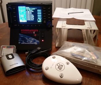
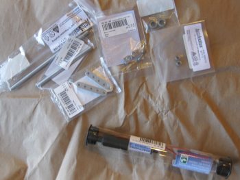
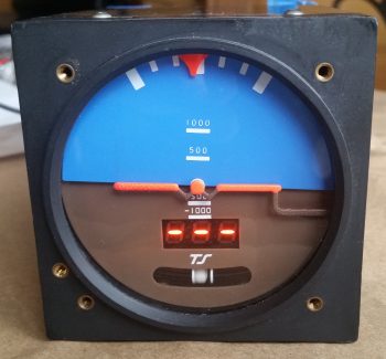
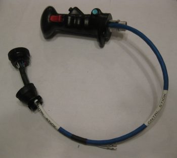
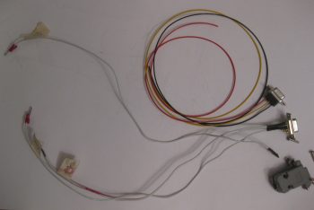
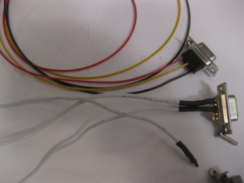
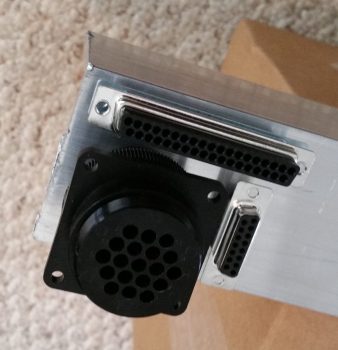
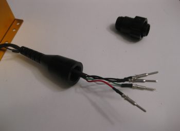
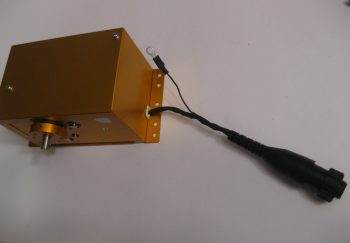
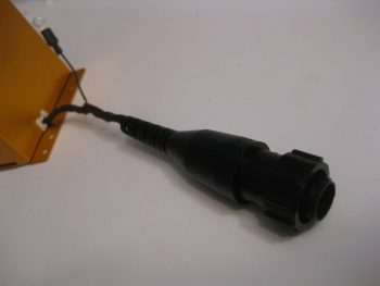
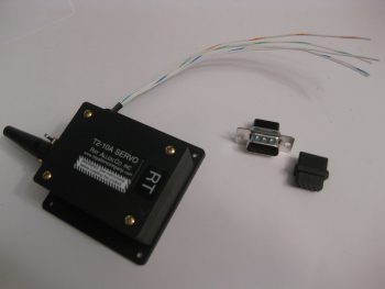
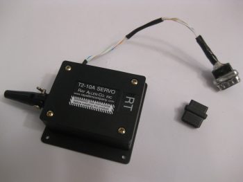
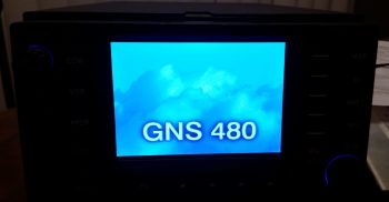
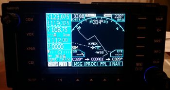
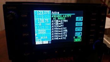
I met with the seller, Phil, at a local airport where I was able to play around with the unit in its Commander docking station.  The fact that Phil was selling an entire Plug-n-play package was the deciding factor in why I pulled the trigger on this unit.  Here are all the components that were included:

  • Garmin checked & software updated to Vers. 2.4 and 5.1 (allows ADS-B+ out)
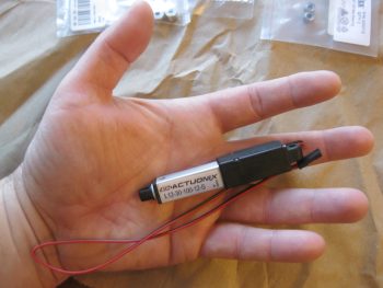
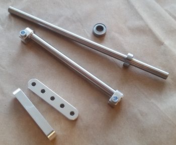
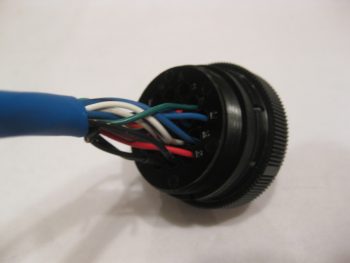
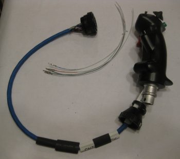
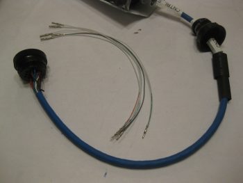
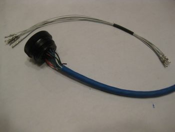
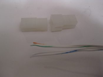
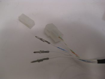
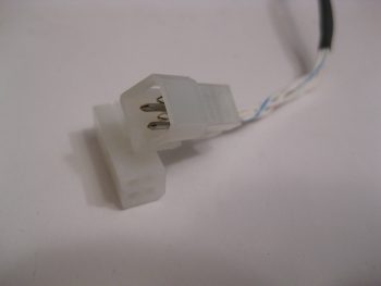
  • Mounting tray (“tube”), backplate and electrical & coax connectors
  • GA 35 WAAS GPS antenna
  • Data card reader + 2 data cards
  • Lone Star Commander docking station

GNS480 FPL screen...w/ comments!

A result of my evaluation, and subsequent purchase, of the GNS480 has brought me to the conclusion that this will be the final and only GPS unit that I plan on installing in my Long-EZ. Clearly this means that my proposed Avidyne upgrade is simply off the table now.  With the GNS480’s handling of voice and nav comms, its inherent WAAS GPS/VOR/LOC/ILS capabilities, and its fantastic handling of airways, I am more than thrilled to have made my decision final in identifying this GNS480 as Long-EZ N916WP’s long term GPS navigator unit.


Chapter 22 – “Danger Will Robinson!”

As I mentioned before, sideline to getting back into the books and refreshing my tired mind on Instrument flying stuff, I’ve been cleaning up some electrical system stuff that is a natural result of integrating systems and devices together.

One such area of my electrical system is on the warning annunciators.  I decided to crack the code on just how these AG6 annunciators (again, I have 2) are programmed.  Well, the programming manual might as well have been written in Mandarin Chinese when I started, but after working through it bit by bit I finally got the swing of it.  The weirdest thing about these annunciators is that you only have one interface to program them, the button –also the annunciator screen– which makes things interesting.  There are only 2 inputs that the screen recognizes, akin to Morse code: a short press [<0.7 sec] and a long press [>0.7 sec].  It also recognizes the rate and combinations of these presses together (analogous to the ‘double-click’ on a computer).  Again, once I worked at it a few times the input was really a non-issue. Add a little patience and it’s actually something new and fun.

One issue I had was that I failed to realize that there was an online spreadsheet that had the codes that I needed to program (or reprogram) these annunciators.  My being remiss in having this critical document on hand was evident after a few telephone and email discussions that I had with Rich from aircraftextras.com.

AG6 Warning Annunciator Screen

With the spreadsheet in hand I was able to effectively program about 80-90% of the input screens that I wanted.  To be clear, I had the installation manual that described the entire programming process, but what I didn’t have was the spreadsheet that had the required codes to tell me what screen ID numbers to input for the warning screens that I wanted annunciated… until after talking with Rich of course!

AG6 Warning Annunciator Screen

Since the AG6, as with what seems like the majority of experimental aircraft products these days, is traditionally geared towards the RV crowd, there are some unique warning annunciator screens I would like that are not on the list of hundreds of screens already preprogrammed on the AG6.

After finalizing all the programming I could do, I determined that I needed 2 completely new screens and slight modifications to 2 other screens to provide me what I’m looking for in my warning annunciation scheme.  The 2 new screens are “IBBS Low V.” for my IBBS unit, and “RAM OPEN” / “RAM CLOSD” for my engine RAM air intake.

AG6 Warning Annunciator Screen

As for the pics above, I would like to point out that the top pic portrays the actual visual appearance the best of these 3 pics.  A brilliant, bright red light is really hard to capture with any of my cameras, and comes out looking orange and pale, and is not representative of its actual appearance (the same thing holds true for the indicators below).

Finally, the top pic showing “CANPY CLOSD” is one that I want changed to “CANPY LOCKD” (there is a screen ID for the latter, but for some reason it too is showing as simply “CANPY CLOSD”).  There will be no “ALT.” screen, but rather “Low Volts” for the main bus low volt state (via the B&C LRC-14 voltage regulator).

The last pic above is the annunciation that will show up for a few seconds immediately following engine start to show that the starter solenoid is not hung up (“hung start”).  As a reminder, a hung starter state is dangerous since huge current flow is rushing through the system from battery to starter and back unabated, which will fry the battery… with even possibly more bad smoking, fiery stuff to follow (Dick Rutan addresses this in CP #99).  To be clear, the more important screens are the red, flashing warning annunciations that will come and stay on until recognized with a screen press, or the warning state ceases on its own.  Thus, the entire time the starter is powered there will be a flashing red light depicting “STRTR ON” until it’s disengaged, at which point the green annunciator screen shown above will flash on.

Moving on…

As I mentioned the other day, in my quest to finalize both my warning annunciation scheme and my device ON/OFF indicators (below) I ran across a discussion from Paul Dye (Editor in Chief of KITPLANES mag) arguing that a simple, separate, non-EFIS or engine management system linked low oil pressure light should be incorporated into one’s lineup as a primary tell-all of engine health if your spiffy, modern glass cockpit goes Red-X on you.

I thought that for 2.3 oz it sounded like some good informational “need-to-know” insurance, so I bought this oil pressure switch from B&C to incorporate its alarm out state as an input into the AG6.  When the oil pressure is low (as in pre-engine start) a red, flashing “LOW OIL P.” annunciation will alarm (this is an adjunct warning light, not a replacement, of the EFIS-depicted engine instrumentation).

Oil Pressure warning switch

This oil pressure switch actually has 3 electrical connections to allow for a Hobbs meter to be wired up as well, if so inclined.  Here’s the back of the oil pressure switch, showing the N.O., N.C. and COM electrical connection posts.

Oil Pressure warning switch

Lastly — something I’m extremely pleased with is these babies below that were delivered today!  Again, as I mentioned before, after I assessed my warning light system I decided that I would revise my original decision to run all but one pair of LED panel indicators through the AG6 annunciators, in order to make the AG6s strictly inflight/actual warning annunciators. Thus, those devices that I simply wanted to know were in an ON or OFF state would get downgraded to just LED lights again.

Now, I did order a myriad of LEDs in one my of Mouser orders, but my spidey sense told me there had to be something better out there.  After messing about online a bit here & there over the past few weeks, I found these.  They’re simple LED indicators for airline cockpit simulators that I found on Ebay (these are 737 panel indicators).  I wasn’t sure if they would work, but at less than $4 a piece, I figured I would pull the trigger and test them out.  I’m very glad I took a chance!

Non-warning ON/OFF LED Indicators

Again, the red and green indicators don’t photograph well, although the blue and amber lights are fairly good depictions of how they look.  These 4 items are the ones which I wanted their ON/OFF states communicated since –other than the fuel pump under my thigh support– I would have no real way of knowing if they are actually in an on or off state (yes, I could tell if the taxi light is on at night, but how about during the day?).

Non-warning ON/OFF LED Indicators

Best of all, these are low current and very lightweight indicators, with all 4 weighing in at less than 0.05 lbs.  I will run them through a dimmer so that their brightness can be dimmed at night, and turned up to their brightest during daylight flying.  One point of note is that I reserved the brightest LEDs (red & blue) for the ground op devices: START ARMED to indicate when the engine starting system is ready, and the TAXI LIGHT on indicator.  This leaves the FUEL PUMP and PITOT HEAT as the less bright, but still clearly visible, indicator lights for flight ops.  In addition, I reserved the only red light, denoting an actual real hazard, for the START ARMED indicator… since a swinging prop typically ensues immediately after it lights up.  So, although definitely listed in the “great-to-know” category, the other indicator lights (and their associated colors) do not denote hazardous states.

Ok folks.  Transmission ended, and back to studying for me!

Chapter 22 – A bit more electrical

Happy New Year!

Over the holidays I’ve been quietly working on the odd & end aspects of various areas of electrical stuff in my push to get as far as I can on finalizing the electrical system before moving on with the rest of the build.

Yesterday I finalized a 2-day process to figure out the wiring going out to the wing Nav, Strobe & Landing lights.  I had a quick but informative discussion with Dean from AeroLEDs and pulled the trigger on a couple different types of shielded 20 AWG electrical wire and some more connectors from Stein.  I also assessed & designed a reroute of my com radio antenna cables to get them away from the noisy wing tip light wire runs.

With final decisions made on the wing wiring, I finalized updating my wiring diagram for the Landing/Taxi/Nav/Strobe lights.  I also updated the wiring diagram for the AG6 warning annunciators, driven in part by my decision to only have actual warning annunciations communicated by the AG6 displays.  Thus, I decided to transfer the simple ON/OFF LED displays for those items that I merely want to know if they are in an on or off state (start armed, taxi light, pitot tube & fuel pump) off of the AG6s.  I ordered what look to be some high end LED annunciator buttons off of Ebay for these 4 ON/OFF indicators.  I’ll assess those when they arrive and move on from there.

I have one more item to report as for warning annunciators: as I was doing my research for what I should employ as simple device ON/OFF indicators, I ran across a post on the VAF forum from Paul Dye (Editor in Chief for KITPLANES magazine) arguing the merits for having a backup Oil Pressure warning indicator that was not integrated into the glass cockpit system… in other words, not reported by the EFIS or the Engine Management System.  I assessed this for a few days, and finally concluded that if I did have a catastrophic display outage and was looking at nothing but red “X”s on the EFIS displays that it would be nice to have ONE annunciator light to provide the overarching status of my engine health, and oil pressure is arguably (as Paul Dye so eloquently does) the biggest. For a weight penalty of 3 ounces, I decided I would incorporate this backup oil pressure status into my warning annunciation scheme.

Today I finally received my L12-S mini-actuator for driving the Taxi Light assembly deployment and retraction.  As you can see in the pic below I bought a number of ancillary parts that should facilitate the install.

Actuonix mini-Actuator & parts

Although I knew it when I ordered it, the tiny size of this actuator is really hard to believe until you actually hold it in your hand, which is exactly what I did!  Again, seeing this pic it’s not hard to believe that this thing only weighs 34 grams.

Actuonix L12-S mini-Actuator

Here’s a shot of the Taxi Light swing down assembly parts that I picked up with the L12-S mini-actuator.

Taxi light actuator hardware bits

I also decided that I was long overdue in doing a thorough ops check of the Trutrak 3-1/8″ ADI that I picked up off of Ebay from an RV driver as an attitude reference backup to my glass panel.  I did a quick review of the instructions and fired it up.  Since I had the GPS puck plugged in I wasn’t quite sure why I wasn’t getting the GPS track info in the window where the 3 lighted dashes appear.  Well, I got back into the manual, did a quick online search and still couldn’t find an answer.  Hmmm, did I have a bad unit that needs repaired?

I couldn’t ponder on it long since I had to run out and help a friend move some furniture (the bane of being a pick-up truck owner!).  Well, I arrived at the location a bit earlier than they did, so I decided to call Trutrak and find out the story on the 3 dashes.  It turns out that the 3 dashes are normal & that no track info is displayed until the aircraft is in motion…. Ok, another good instrument ops check!

Ops checking Trutrak ADI

Tomorrow I’ll test out my taxi light actuator circuit design & operations by wiring it up to the DPDT relay I have on hand.


Chapter 22 – Infinity Stick Grip

I started out today cleaning up the RivNut installed on the triangular panel support.  I knife trimmed the excess 2-ply BID layup and pulled the protective tape from the top of the RivNut.  I then function tested it as you can see below.  Works to plan so far!

With the new Adel clamp in place for the Infinity stick grip cable, I could then check the proper slack for the cable, mount it in the Adel clamps, then mark the cable for cutting to length.

Measuring stick control cable for cutting

I pulled the stick grip out and took it to my mad scientist’s electrical laboratory upstairs. Before starting work on it however, I spent a good 1-1/2 hours reconfirming the wiring pinouts for the P5 connector.  I consolidated 4 ground wires coming out of the stick grip into 2 wires to give 5 open pins, which enabled me to piggy back 5 wires into the P5 connector: 4 for the roll trim servo (behind the pilot’s seat) and 1 for the ELT GPS signal (like many other builders have done, my ELT will be positioned on the outboard fuselage sidewall, on the inboard side of the right strake’s baggage compartment… so just aft & outboard of my right shoulder).  As I was configuring the P5B half (the stick grip side) of the connector, I went ahead and spent another good hour+ figuring out the P5A side of the equation, which is the all points yonder (Triparagon, PQD, panel) side of the connector. It took some time since this process required a good bit of verification & cross-checking with the various electrical diagrams and the component installation manuals.

I had already gotten a late start since I was up late (working on this build!) last night.  I ran out to run some errands in the late afternoon and to pick up some small 4-40 stainless steel screws from a local hardware store that still has a wall of hard-to-find hardware in their back room.  When I got back I toned out all my stick grip wires to check continuity and verify wire colors, since I had swagged some guesses on them as I was building the P5 pinout diagram. With my P5 pinout up to speed, I did some prerequisite tasks for terminating the P5B connector onto the stick grip such as printing out shrink tube labels. For the 5-wire roll trim piggyback cable I checked availability of parts, since I have 4-pin mini-Molex connectors on hand and I need at least a 5-pin (which actually means 6-pin). Again, I don’t want to use a 9-pin D-Sub here, so I added a couple of 6-pin connectors to the Stein order that I’m compiling.  Boy, it’s an obvious statement I know, but the nit-noy parts buying process for these builds is ENDLESS!

Ok, with it being a bit later in the evening, before I started on the terminating the P5 (B side) connector on the Infinity stick grip cable, I wanted to make a decent amount of noise on the Triparagon cross shelf.  Thus, I detoured from the stick grip cable for a bit to drill 10 new lightening holes into the cross shelf — 8 small diameter and 2 bigger diameter holes. The 2 bigger diameter holes, just to the right of the center brackets in the pic below, sit immediately above the mounted Piezo warning horn (bigger, lower hole) and the gear & canopy warning module that I mounted tonight (see next pic).

10 more lightening holes on cross shelf

Yes, folks, it’s the marvel of modern technology! Getting a gear & canopy warning module into the space of a couple of stacked matchboxes . . . why it’s just pure science!  (ok, and integrated circuits… ha!)  Not wanting to NOT gain any progress on the Triparagon today, I mounted the nose gear & canopy warning module with some -6 CS SS screws.  As per usual, I drilled the countersinks on the topside of the Triparagon cross shelf, although admittedly one of the holes didn’t want to cooperate and the countersink is a bit larger, lopsided, and messier than I would prefer.  Still, once the screw is in & the module mounted it would be bit difficult to tell unless really looking hard at it.

Freshly mounted gear/canopy alarm module

I brought the Triparagon cross shelf back upstairs and weighed the whole thing without any mounted stuff.  It currently weighs in at 0.57 lbs, which when added to the Triparagon vertical plate at 0.7 lbs gives me a current total weight of 1.27 lbs.  This is about a quarter pound heavier than my 1 lb goal weight.  The prescription?  I gotta fever for some more lightening holes!  So back to the drill press for another round of sharp-bladed weigh loss!

I then started (finally!) on terminating the Infinity stick grip cable wires for the P5 connector, B side.  After taking a big breath and cutting the cable to length, I then slid the plethora of heat shrink tubes & labels onto the cable.  I then cut the outer cable jacket to expose the 17 inner wires.

Prepping control stick cable with labels

I didn’t take a bunch of sequential pics, so here’s what I did: I started off having to find & verify the pairs/groups of wires for each switch in the control stick.  As I found each new set, I would strip the end of the wires, terminate them with an AMP CPC socket, check continuity, and then mark them off the list.  I also used small pieces of masking tape to keep the pairs/groups of wires together.  After I terminated all the wires, which included 2 sets of 2-pair ground wires, I then double-checked the electrical continuity and then snapped them in place into the correct numbered socket hole.  I then rechecked continuity again just to ensure I had gotten it all right… which I didn’t.  I swapped the 2 green wires and had to pop them out and reinsert them into the correct socket positions.  I toned out the entire cable again to ensure the sockets were in the correct position with electrical continuity, which they were.

Stick grip cable wires terminated into connector

I then went down to the shop, measured the required length of roll trim & ELT GPS pigtail legnths at 10.5″.  Instead of using the 5-wire cable that I have (you’ll see that in pics tomorrow), I decided to simply use free 22 AWG wires. I actually started collecting the wires with the correct color codes (ie white with blue stripe, etc.) when I realized that instead of wasting my good multi-colored wire, I would simply use white wire and use a Sharpie to mark the correct color on the last couple of inches of the wire.  For the the two plain white wires in the bunch, I simply swapped out the white wire at pin #2 for a grey wire, so no confusion would set in while I await my 6-pin mini-Molex connector from Stein. I then terminated the 5 each 22 AWG pigtail wires with mini-Molex pins.

Stick grip cable wires terminated into connector

I then terminated the other end of the 5 pigtail wires with AMP CPC sockets. I verified that my crimps on the terminated wire ends were good by doing a continuity check on each wire.

Roll trim wires and ELT GPS wire

To keep the 5 pigtail wires under control, I threw on a small piece of black heat shrink.

Roll trim wires and ELT GPS wire

I then snapped the pigtail wires into their appropriate socket holes in the back of the P5 connector.  I also went to town on the cable with my heat gun and shrunk all the shrink tubing and labels in place.

Roll trim wires and ELT GPS wire installed

I then did a final continuity check on the pigtail wires, and with that all that was left to do was to mount the cable clamp, that I conveniently did not forgot to put on the cable this time!

Grip stick cable connector ready for cable clamp

Here’s the Infinity stick grip cable terminated with the P5 AMP CPC connector and 5 pigtail wires that will go into a 6-pin mini-Molex connector.  If I wasn’t clear on the pigtail use before, it will allow the 4 roll trim/1 ELT GPS wires to transit into the P5 connector, but still allow me to disconnect the roll trim/ELT GPS cable at the 6-pin mini-Molex connector when I simply want to remove ONLY the Infinity stick grip and cable from the plane. Clearly, in this scenario, once the 6-pin mini-Molex connector is disconnected the 5-wire roll trim+ELT GPS cable would remain mounted under the right armrest.

Stick grip cable with roll trim pig tail completed

Here’s a couple closeup shots of the P5B connector with the cable clamp in place.

Grip stick cable connector cable clamp

Grip stick cable connector cable clamp

I realized as I remounted the control stick, ran the stick grip cable and screwed the P5B connector onto the P5A connector at the P3/P5 mounting bracket that I’m going to have to carefully trim the back outboard corner opening of the armrest to get that big mojamma P5B connector into the armrest!  After that it traverses through the lower instrument panel bulkhead hole fine.

Grip stick cable and connector test install

Also, I’m very happy with the stick grip cable run since it keeps the cable nicely tucked out of the way from the elevator control tube range of motion.

Grip stick cable and connector test install

Here’s a final shot of the freshly terminated stick grip cable connector and installed cable.

Grip stick cable and connector test install

Tomorrow I will continue to work on the 5-wire roll trim+ELT GPS cable  and try to finish up the Triparagon installation.


Chapter 22 – Sloggin’ it out!

Today I started out by finalizing my pitot-static system plan.  I still need to make some phone calls tomorrow to some of system vendors to ensure I’ve got the most optimized configuration for hooking up the pitot-static lines on their respective systems, but beyond that I’m pretty much done.  I’ll be dropping an order to Stein here soon and it will include the remainder of the parts I need to complete my pitot-static system install.

Pitot-Static System

In addition the pitot-static system, I also reviewed & assessed my recently added Triparagon connectors that should allow me to remove the instrument panel fairly easily.  I found a few more issues that made me add the Trio autopilot’s wiring harness to the list of components that require me to simply remove the connector.  The main issue with this harness is that there are shielded wires that run all the way back to the roll servo.  Clearly these are not easily removed, and I’m sticking to Stein’s advice (because I agree!) to NOT add connectors in the middle of shielded wire runs.  Thus, this requires me to remove the Trio autopilot’s connector and leave it in the plane when I remove the instrument panel. In short, I made a lot more progress on the concept of running all the instrument panel components’ wires through connectors to allow EZ removal of the panel.

Later on, I figured I would get some wiring done while I was watched football.  Since I had just had the Trio autopilot wiring harness out, I decided to re-terminate the roll servo pins with AMP CPC pins vs Molex, and add the AMP CPC connector housing.  I’m not messing with the pitch servo since it needs to be cut significantly shorter and I need to get a good measurement for that.

Trio autopilot wiring harness

The pic below shows how the connector pins looked before I started.  Again, I cut the Molex pins off and reterminated the wires with AMP CPC pins and then mounted the connector housing for the roll servo cable.

New A/P roll servo AMP CPC connector

Continuing on, perhaps a little ironically I removed the 9-pin D-Sub connector from the roll TRIM servo and swapped it out with a 4-pin Molex connector I got from Stein.  As you probably know, I’m not a huge fan of Molex connectors, but I figure any roll trim servo failure is fairly benign in the operational realm of flying a Long-EZ.

"Old" Roll TRIM Servo connector

I started by cutting off the D-Sub connector as close to the connector housing as possible.  In both pics above and below you can see the 4-pin Molex connector housing.

Swapping Roll TRIM servo connector

I then reterminated the wires with mini-Molex pins.

New Roll TRIM servo Molex connector pins

And then snapped the pins in place into the Molex connector housing.  BTW, this connector is J6.  I’ll of course wait to terminate & add wires to the other half of the connector when I actually install the roll trim servo.

New Roll TRIM servo Molex connector

My last action of the evening was to rewire the wiring harness for the TruTrak ADI.  As I was taking inventory of all the wires, which included digging into the manuals, I noted that the wires on the TT ADI’s wiring harness connector were simply HUGE!  Although the installation manual calls out for 22 AWG wiring, these wires range from 14 to 18 gage… way too big!  Since the wires were soldered into the 9-pin D-Sub connector, I simply created an entire new TT ADI wiring harness D-Sub connector with crimped pins.  I of course used 22 AWG wires for the new harness.

Rewiring TruTrak ADI wiring harness

Here’s a closer shot of the new TT ADI wiring harness (red, black & yellow) that will replace the old one (white wires).

Rewiring TruTrak ADI wiring harness

Tomorrow I’ll finish the plan for the wiring, finalize the positions of the airspeed switches and other Triparagon cross shelf mounted components (“CrackerJack parts!”) and attempt to get the Triparagon cross shelf mounted.  I’ll most likely order the pitot-static parts as well after talking to a few equipment vendors.


Chapter 22 – Unraveling the mystery

Over the past few days during the Thanksgiving holiday I’ve actually been getting a fair amount of electrical system documentation, planning & system design work done.  Some things I’ve done, like taking the time out to figure out the wiring & pinouts for the Infinity pilot control stick buttons, switches & wires, is pretty much a known quantity and simply needed to be completed & checked off the to-do list.

Determining P5 connector pinouts

But the pitot-static was a different animal entirely. I had some pieces parts on hand, but I really needed to get educated on pitot-static systems before starting out.  During my research I ran across a very nicely detailed post on the VAF forum from Paul Dye (editor of KitPlanes mag) concerning his pitot-static system.  In the post he not only described his pitot-static system, and the advice that Stein (from SteinAir) –who we know is a genius on all things panel related– gave him, but how he also devised his pitot-static system, and in turn his electrical system, to allow for the panel to be removed EZily.  Hmmm?!

I played around with designing my pitot-static system with the intent to get it documented in PowerPoint and on paper, but have not gotten around to either yet.  Although I pretty much have the pitot-static system designed in chicken-scratch form & in my head, as you can see below (the diagram below was summarily stolen from a guy asking questions on his p-s system that posted it to VAF…I’m merely modifying it to suit my needs!).  But the panel removal idea –one that Marco and I have discussed non-specifically many times– began to gnaw at me more & more each passing day over these past few days.  It was definitely germinating in my brain.  One overriding reason is that if I could pull it off, it could literally change the structure & process of how I build the nose of my plane.

Planning/Configuring pitot-static system

So today I spent the entire day taking inventory and listing out every single wire that comes off the panel mounted avionics, instruments, warning lights, buttons, switches, etc. I determined what connectors would need to stay connected, and which ones must be disconnected for the panel to be removed.  I created a whole new series of connector designators for the D-Sub and Molex series connectors: J1 – Jn, as compared to the current series of the AMP CPC connector series: P1 – Pn.  

After hours of collecting this data, and determining that it could be done, then I got to the business of updating the majority of my electrical diagrams to reflect these new intermediate connectors.  I determined a couple of things, at least initially:

  1. The majority of switches will be on separate sub panels that will be removed from the panel before it is removed.
  2. The Avidyne P1002 communications connector and the Dynon intercom connectors will have to be removed and stay on the plane side due to the multiple cross/inter- connects to components and the shielded wiring.
  3. Given the factors above, I determined the number of pins required could be provided with 37-pin (J4) and 15-pin (J3) D-sub connectors, and utilizing the 19-pin AMP CPC connector (P6) that I had previously planned on using for the GIB stick grip.  These should give me enough pins for the panel wiring, with some extra slots.  The AMP CPC (P6) and 15-pin D-Sub (J3) will handle primarily power & ground wires, while the 37-pin D-Sub (J4) will handle primarily signal (a ton of RS232) wires.

Panel removal electrical connectors

Of course I need to confirm and refine my plan, but with this in hand and the finalizing of the pitot-static routing plan, I’ll be able to finalize the component placement on the Triparagon, get the top cross shelf and side mounting tabs cut and lightening holes drilled. I’ll also be able to roll these new factors into the design of the top nose structure and see how it effects the forward canopy skirt.  Tomorrow will be a light build day, but I do plan on getting a few hours more done on this stuff.


Chapter 22 – Electrical System

Of course at this point my electrical system is analogous with the Triparagon.  Since, that being said, it is true too that the majority of my electrical components are mounted, or will be mounted, on the Triparagon.

After spending a good couple of days here & there populating the Triparagon components with wires to & fro the various parts, and finalizing a large number of circuits for the resident things on the Triparagon, it then stood to reason –and begged the question: Does it work?  Yes, it was truly time to test install this monstrosity.

So I did a mock up install of the wired-up Triparagon onto its mounting tabs in what I call the Avionics Bay (instrument panel to F22) of the Long-EZ.  I also installed the Voltage Regulator to see how it fit into the mix.  Below you can see the left side of the Triparagon & the Voltage Regulator.

Triparagon mock install

And a shot of it from the right.  I’d like to point out that up to this point the Triparagon has definitely met, or exceeded, my design goals.

Triparagon mock install

To give you all a sense of space…. specifically the space NOT taken up by the Triparagon (aka “legroom”) I took a couple of shots from close to straight in line with the edge of the the NG30 plates that house the nose gear motor.  In addition, the nose wheel cover (NB) also provides a “natural” barrier & offers a bit of standoff protection from wayward feet or legs to help keep the Triparagon out of accidental harm’s way.  I would like to point out that the current Triparagon wiring is in the initial “free form” stage and has not been organized, nor secured in place yet.

Triparagon mock installTriparagon mock install

There’s still just a bit of cross-connect wiring that needs to be done on the Triparagon proper, along with some final prep of the mounting tabs and the installation of the top cross shelf before I move back onto installing the wheel pants.


Chapter 14/23 – An Enigma . . .

Before I get to the “enigma” part of this story, I wanted to show you one piece of what Marco & I were into last night.  We started off out in the shop and of course had a myriad of discussions on all things Long-EZ.  He brought some Long-EZ seat cushions he has and we tried them out both in the front & back seat.  This visit is the first time Marco has sat in my fuselage, and he did note the difference in feel between my 1.4″ wider cockpit vs. his stock flying plane (he widened his build Long-EZ fuselage 2″).

The more exciting part of his visit is that right before we went to dinner I hooked up a 12v battery to charge while we were out. Then, when we returned, we fired up the GRT Mini-X EFIS for the first time ever.  Marco was curious to see how it looked and requested that we take a look, so we messed around with the screens, menus, features, etc. for a good while. We didn’t take any pics last night, but below is some of what we saw with just power and the GPS antenna hooked up to the Mini-X.

Primary Flight Display (PFD):

GRT Mini-X PFD

Navigation Maps (Track up & North up):

GRT Mini-X MapGRT Mini-X Map

HSI:

GRT Mini-X CDI

Today I started out by lifting the fuselage nose to get the longerons to a level 0°.

Setting fuselage to 0 degrees

Longerons at a level 0°.

Setting fuselage to 0 degrees

I then checked the firewall and it was dialed right in at 90°, perpendicular to the longerons.

Firewall at 90 degrees

I calculated the thickness of the firewall (since I haven’t glassed on all the BID yet) at 0.355″ and simply rounded that up to 0.36″ and added it to the 1.6″ for the part of the engine mount extrusion sticking out aft of the firewall for the engine mount to attach to.

Marking extrusion at 1.96 inchesMarking extrusion at 1.96 inches

After removing the firewall, I mocked up the engine mount extrusions (remember, the top ones are a mixture of 4130 steel on the left side and 2024 aluminum on the right) and then checked the WA16 Spruce wedge spacers.  Since my fuselage is just slightly more curved, I cut the WA16s 0.4″ at their widest point vs the stock 0.3″.  This of course turned out to be a wasted effort since even though the fuselage is more football shaped than stock, the plans 0.3″ wide wedge spacer dimension is still the correct size.  Ahhh, so I did even more cutting and sanding to get these things thinned down.

Engine mount extrusions in place

I then clamped and set the engine mount into place, only attached to the upper engine mounts for the initial look.

Engine mount setupThis is where the ENIGMA part comes into play.  I have no idea why, since I thought I was Uber diligent in my measuring of all fuselage dimensions at the beginning of this build, but the face of my firewall is setting at about FS 125.4 vs the plan’s FS 125.0.  I have to admit I was remiss in double-checking the firewall dimensions when I installed the CS spar into the fuselage, since I assumed that my spar notches were good due to the fact that I did re-check their measurements.  Plus, the firewall fit flush and appeared aligned, which it is . . . just 0.4″ aft where the face of it should be.

The real affect, although over-comeable, is that the top set of engine mount brackets are setting at FS 134.5 vs FS 134.2.  0.3″ may not seem significant, but it certainly is to the W&B when you’re talking about the mounting of the 250+ pound engine, the heaviest component on this entire craft.

My initial concern was that if I simply move the mount closer (which will require some trimming of the upper engine mount stems) that it would negatively effect the clearance of the forward-mounted engine components.  But since I’m using Electronic Ignitions in both magneto mounts, they won’t require the forward space that Slick mags do.  Thus, if I trim a hair over 0.3″, and mount the engine with it’s normal engine mount stem to firewall spacing, I should be very close to spot on with the FS 134.2 engine mount setting.

[BTW, the measurement below was taken from the face of F28… so, 28 + 106.5 = 134.5].

Engine mount 0.3" too far aft

This shows the gap between the end of the right longeron and the upper right engine mount stem.  Note that if the engine mount stem were left at the length in the pic below, it would actually be embedded into the firewall.  The aft face of the firewall will be just forward of the double horizontal extrusion plate shown just underneath the engine mount stem.

Engine mount to longeron spacing

Tomorrow I’ll actually trim the engine mount (too late tonight due to noise) and continue to work the engine mount extrusions.  I do plan on getting the layups & upper engine mounts in tomorrow.  Also, as you can see –at least for the time being– I’m pretty much done with Chapter 16, Controls.  Finally, there’s some important info concerning my upcoming build schedule in the project update post.


Chapter 17/22 – All Electric…

This morning I had to run over to get a new muffler on my truck, which ended up taking half the day.  I went to a cafe and had some coffee while I waited for the truck to get finished, and while there I made up my to-do task sheet for the day.  Unfortunately, I only got the first 2 items on the list done, each of course taking a bit longer than I had anticipated.  By the time early evening rolled around, I punted and simply went to dinner & a movie with a buddy of mine, so not a lot done on the actual build of the plane today.

My first task was to prep the connection wiring and replace the connector on the Trio Pro Pilot roll trim servo somewhat like I had done with the pitch servo.  The main difference here though is that the roll servo will reside in the engine compartment, not the cockpit, and thus will be subjected to higher temps and more of the elements.  I wanted to completely protect this wiring and replace the Molex connector with an AMP CPC connector.

Trio AP Roll Servo

I started by removing the Molex connector.

Trio AP Roll Servo Molex pins

And then removed the 4 individual Molex connector pins.

AP roll servo Molex pins removed

I added a couple of pieces of heat shrink, a flexible wire stay, and crimped 4 new AMP pins onto each of the wires.  Technically, in the same way that as the pitch servo, there are 2 ground wires that share the ground pin connector: one to the internal electronics, and one for the case ground.

AP roll servo AMP pins crimped on

As you can see, I also crimped a ring terminal in place for the case ground wire.  In addition, I snapped each AMP pin into the AMP CPC connector housing and closed it all up.

AP roll servo AMP CPC connector

And a closer shot of the final AMP CPC connector configuration for the Trio Pro Pilot roll servo.

AP roll servo AMP CPC connector

My second (and final) electrical-related task of the day was to terminate the 24AWG wires coming out of the RAC servo that I’m using in my roll trim system.  I decided to try a little trick that Bob Nuckolls has for modifying a DB9 connector to use as an inline type connector.

Below you can see I’ve already removed the metal housing from the female side of the DB9 connector.

Roll trim servo unterminated 24AWG wires

I then had to remove the tabs from the male side, but this being my first time making one of these I removed a bit too much of the flange, so when resoldering the sides back together I had to try to bridge the gap, which if you’ve used solder you know it’s not a good gap filler or bridging material.  I later cleaned off some of this excess solder but pressed on after I took this pic to get this thing completed.

Modified DB9 connector for Roll trim servo

I guess I should have taken an interim pic of the individually terminated wires with the D-sub pins, but here’s the final connector after I added some E6000 adhesive for essentially a potting material & strain relief on the back side of the connector.

Modified DB9 connector for Roll trim servo

The female side of the connector will get D-sub sockets terminated onto the wires and with the wires terminated, all of this will get heat-shrinked together to complete the final connection of the 2 connector halves.

Modified DB9 connector for Roll trim servo

For what is essentially a 4-pin connector I’m not really sure if I’d use one of these again.  I think for the future I’ll look for a more elegant off-the-shelf solution to use for the RAC servo wiring, or any smaller gauged wires for that fact.

I’ll be heading to the AOPA fly-in at the Frederick, MD airport tomorrow, so won’t get anything done until maybe early evening… we’ll see!


Chapter 9, 13, 16 – A myriad of stuff

I started today off by peeling the peel ply off the autopilot pitch servo mounting pad & doing some minor cleanup around the edges of the layup.

I then mounted the pitch servo with the control rod in place to show what it will pretty much look like when installed operationally.

AP pitch servo mountedAP pitch servo mounted

I took the pic below with my phone and included it here because it shows the actual color much better, which is a rich yam orange vs. a sweet potato gold showing up in the pics above.

AP pitch servo installed

I had to run out and run some errands for a few hours, but when I returned home I went to work on fixing the “crease” that was running down the middle of my Infinity stick grip. Something was misaligned inside to cause a noticeable edge of one half of the stick off from the other.

The first thing I did was to “crimp” the adapter I bought from JD at Infinity to more closely encircle the adapter I made.  The second thing I did was reroute some of the internal wires that I think simply had nowhere to go so was bunching up a hair and knocking the halves just slightly askew.

Still, it was the proverbial “herding cats” game but I finally got it.  I then torqued the screws down to keep it that way, only to read a few minutes later in the instructions:  “Don’t over tighten the screws!”  . . . oh, well.  They are tight!

Infinity stick grip bracket re-install

So far the problem is solved, but I’ll have to play around with it for a while to see if it regresses before I add blue Loctite to the threads.

For those of you more esoteric types that like more pastel colors, like turquoise, I offer you this . . .   I call it, “Nouveau Grip.”

Nouveau Stick Grip

So, there I was . . . it was late afternoon, and the days are getting shorter.  Also, this warm weather spell is supposed to end tomorrow so I figured I had better get outside and do some saw work . . . er, uh, I mean some milling work!  Ok, milling work on a poor man’s milling machine, aka “a table saw.”

I bought a 2.5″ wide x 0.5″ thick bar of 2024 from ACS specifically to make my inboard mounts for the wheel pants.  I did a quick measurement of one of the inboard axle bolts & plate, then marked off the 2024 bar stock for cutting.

2024 bar stock for inboard wheel pant mounts

I stole the idea for these from Bernie Siu, who ended up with this style after 2 prior iterations of inboard wheel pant mounts, including the original style called out by Gary Hertlzer in the instructions.  These are bit more “elegant” in style, and if all plays out the way I intend, the horizontal “bar” will be able to be used to jack up the gear leg to change tires, etc.

I want to point out that these are in the ROUGH stage, since, as I mentioned before, I had to use the poor man’s milling machine to get these ginned up.

ROUGH 2024 inboard wheel pant mounts

Here’s a profile shot of the wheel pant inboard mounting brackets.  I thinned the top and bottom plate material down to 1/8″ by cutting into the 1/2″ bar 3 times, an 1/8″ at a time (for a total of a 3/8″ deep cut).

ROUGH 2024 inboard wheel pant mounts

The shot below is more to show the other 2 pieces I cut from the 2024 bar stock, and that’s a 3/8″ x 3/8″ x 1.2″ plug that will go into the end of a 1/2″ x 1/2″ 6061 square tube that I’m using as a crossbar for the GIB top seatbelt straps.  Since riding in the back of Marco’s Long-EZ, although not bad at all, I can see where there could easily be a need for folks to bring the top seatbelt straps in closer together.

My bar will be secured in 3 places: on each side with the forward engine extrusion bolt into the CS spar as the original plans upper seatbelt bracket tabs were.  And then in the middle of the bar into a hard point in the CS spar.  These 2024 square plugs will reinforce the hollow tubing for the 1/4″ AN4 bolt that will get installed vertically through each side of this bar to hold it and also, more importantly, secure the engine mount extrusion in place to the CS spar.

GIB upper seatbelt x-bar 2024 reinforcement plug

With my metal cutting tom-foolery behind me, I started working on a quasi-requirement of Trio for the autopilot.  In the manual it states to not have the autopilot act as the hard stops for the aircraft control system.  Although we don’t have hard control stops in most of our Long-EZs, I decided I would do what I could and put in a stop for full aft stick.

I had originally thought I would put a stop in both sides, under each torque tube offset arm. I may still do that, but for now I decided to just do it under the offset arm where the pressure is getting applied from the control system: the right side.  Nonetheless, when I decided this, I had already marked the area on the bottom of the canard where the finish needed to be removed to get to bare glass (below).  I did this for both left & right sides.

Finish marked for removal for control stop

Finish marked for removal for control stop

Here’s a couple shots with the finish removed, and with the glass sanded and ready for glassing.

Finish removed for control stop

Finish removed for control stop

Here’s a long view with the elevator control hard stop in place.  The elevators are set at just a skooch over 30° at about 30.5°, just to make sure the full operational limit is obtained.

In addition to Trio’s requirements (which apparently I’m meeting only 25% of!  …. actually, I talked to Chuck Busch and he said all was good with my install plan!), I found an old CP (CP# 48 pg 4) that stated some canard pilots were having issues rotating if they pulled full aft stick and the elevators went past 30° down.  This gets into the backside of the lift curve and interestingly may not get the nose of the plane off the ground.  As per the CP, in this scenario one would be “on the “back side” of the lift curve, lift is less than maximum and the elevator is creating lots of drag.” Marco was having some of these same type of issues on his plane, and found that NOT going full aft stick on takeoff was giving him better liftoff.  Of course I’ll test it out and adjust the stop as necessary IAW this CP.

Testing control stop depth

Here’s a closer shot of the elevator control stop.

Testing control stop depth

I then floxed the elevator control stop in place, made some flox fillets and glassed each side with 1 ply of BID initially.  Then, since I had enough epoxy, I added one more ply of BID to the inboard side since my first NON-prepregged piece of BID decided to go just a tiny bit wonky on me.  I then peel plied the glass intersection on the canard surface.

Elevator control stop floxed and glassedElevator control stop floxed and glassedElevator control stop floxed and glassed

Later in the evening, I reinstalled the Infinity stick grip in the arm rest and tested it out.  Alles ist gut!  . . . so far.

I realized the other night that my initial estimations on where the rudder pedals needed to be mounted were way off!  I guess I’m just a lot taller than I remember (ha!) because twice I had to remount the rudder pedals farther forward.  In addition, the space in the nose is TIGHT, and I may have to lop off the inboard tubes that make up the “T” on the rudder pedals.  Currently, it’s just too difficult to set my feet along side them as if I were in the relaxed cross country mode, then bring my feet back onto the pedals.  My shoes snag on that top pedal crossbar and make it a real hassle to get my feet back on the pedal.  Since it’s so narrow on each side anyway, I doubt if lopping off that extra metal tubing will affect my ability to mash these pedals when needed!

Adjusting rudder pedal positions

With a really good idea of my pedal geometry now, I decided to re-attack the placement of the Atkinson pitch trim assembly.  After mocking it up in different spots for a bit, I pretty much concluded that it has to go where I had planned for it to, except with one minor modification: it most likely will have to be mounted at an angle with the actuator motor leaning from 30-45° inboard to clear the upper curvature of the nose.

Test fitting pitch trim assembly again

Tomorrow I have to get some work done on my truck, then run some more errands.  I plan on finalizing some more of this perpetual odd-n-end stuff and hopefully move onto doing stuff that’s actually covered in the plans!