Chapter 18 – Canopy frame interfaces

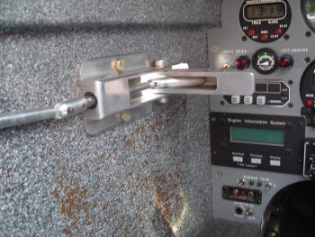
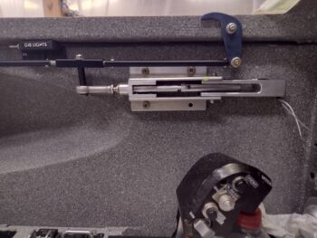
Today my efforts over the last week finally culminated in the completion of the canopy latch handle install.  I’m happy to report that it is working quite well, and after a good hour’s worth of work I dialed it in even further after removing the pilot seatback push-pull thru-tube, drilled out the rivet securing the aft threaded insert, trimmed the tube by about 3/8″, made a new threaded insert and drilled/riveted that into place.  A couple subsequent rounds of trimming the new threaded insert to length and I had all my latch hooks aligned at the same angle and elevation.

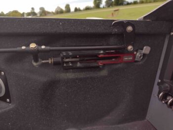
And here we have the installed canopy latch handle, connected to the 4 latching hooks via a HEIM rod-end (this provides just the flex needed in opening and securing the hook push-pull tubes to secure the front hook in place… I stole this design from Howard Caulk).  Also note the newly designed, single switch (no extra “Flux Cap.” switch) box for the GIB lights, with the wire “cable” attached under the longeron going forward.

The reason behind this last round of tweaks on the canopy hook push-pull tube lengths and positions was due to a slight angle showing up on the exterior handle when the canopy was CLOSED & LOCKED.

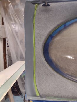
You can see here the aft end of the handle (right side) peaking out just a hair more than the front.  This was an indicator that I wasn’t getting full closure of the handle into its locked position.  I remedied this with all my shenanigans above…  Now, also note the curvature of the fuselage at the longeron underneath the canopy (blue) lip.  I wanted the canopy latch system completed and operational to then allow me to rework this area to clean it up and smooth out this interface.

Although my canopy latch system is operational, I still needed to correct the NOW slight mismatch between canopy skirt interior groove that interfaces with the vertical extending aft lip of the glare shield on the aft nose/avionics cover.

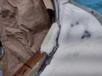
To do this, I removed the front seat back cushion, climbed into the cockpit upside down so that my head was just inside the left leg hole under the instrument panel, with my legs hanging over the pilot seat back.  I then closed and locked the canopy so that I could mark the aft edge of the vertical extending aft lip of the glare shield inside the canopy skirt groove, which I had added green tape inside of before hand.

This is the result of that effort… note the red Sharpie line on the tape.

Also while I was in this most precarious position, I grabbed a shot of the gap between canopy lip and longeron caused by the glare shield lip being a bit too far forward and not allowing the canopy to seat fully closed.

To remedy this issue between glare shield lip and canopy skirt groove, I had to either A) reposition the groove in the canopy skirt, B) reposition the glare shield lip aft, or C) remove the glare shield lip altogether.

I’ll note that since there is a rubber edge that will be attached to the glare shield lip, that then is a seal pressed up into the canopy skirt groove, I did not go through all this work to simply eliminate this feature.  So option C was a no-go.  As was option A since it would simply be too difficult and time-consuming to rework the groove in the canopy skirt.

So option B it was: move the glare shield lip aft approximately 1/8″ to get it reseating near the center line of the canopy skirt’s interior groove.

To accomplish this, I added double sided tape to the existing glare shield lip, then a thin strip of cardboard covered by electrical tape.   Before removing the aft nose/avionics was off the plane, I marked the line where the overhanging glare shield met the instrument panel overhang since I didn’t want to add any thickness in between the pre-existing clearance between cover and nose structure.

This gave me about an inch just forward of the glare shield lip to glass 2 plies of BID over the tape and cardboard I had just added to the lip, but not before I wetted out and laid in a strip of peel ply on the vertical edge before the glass went on.

After laying up the 2 plies of BID, I then peel plied the external/top side of the layup (cover being inverted) and left it to cure overnight.

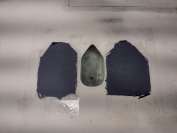
I had a decent amount of Pro-Set epoxy left in my cup, so I cut 4 pieces of peel ply and 4 plies of carbon fiber.  I had planned on doing my bottom side wing bolt hole covers actually on the bottom side of the wings, but decided they would be flexible enough to make them on the top.  Besides, I didn’t want to waste epoxy.

So I added tape on each side of the upper bolt hole access hole on the top of the left wing, and then laid up the 2-ply CF wing bolt hole covers, with peel ply on both sides of the layup.  Again, these are for the bottom sides of the wings.  I then left these to cure overnight as well.

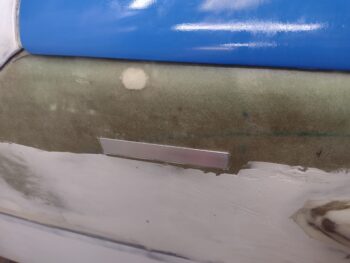
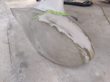
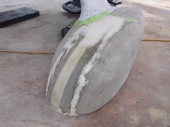
Finally, with the last bit of epoxy I had in my cup I mixed up some micro/West 410 and applied it to the already taped off right wheel pant, on the front half (pic 1).  I had already done this previously on the left side (pic 2), but just hadn’t grabbed a pic of it yet to report in a blog post.

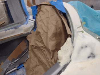
My final task of the evening was to add some filler pour foam in the aft corners of the fuselage-side canopy frame, where the longerons meet the D-deck canopy lip.  When I trimmed down the canopy frame at this corner in its curved fashion, it left a decent gap at these corners, so I’m remedying that now.

Here I’ve added pour foam —which I just got a new batch in a few days ago— and have just pulled the forms off the cured foam, so both sides are in their raw state.

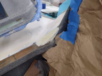
And here we have we the first initial round of clean up and contouring of the added pour foam at the aft longeron/D-deck corner intersections.

It was fairly late in the evening at this point, so I’m kicking off the final shaping (then glassing) of these pour foam corners until tomorrow.

Slowly gettin’ er done!

Chapter 18/22 – Helluva way to build!

OK, so I was out of town for a 3-day weekend, and upon my return got some more stuff done in regards to the canopy latch assembly.

Here is the canopy latch handle that I machined all cleaned up, as best possible, with a few minor nicks & scratches in the aluminum still showing.

Another shot of the cleaned up canopy latch handle.  These shots were taken just immediately PRIOR to me drilling the small hole all the way through the handle in the lower left corner (as situated in pic below) for the forward push-pull rod securing roll pin.

I then had a series of near-laughable (if not all-out angering!) events happen that knocked me off my plan and down a diversionary rabbit-hole for a good couple of days.

I had redesigned and modified the “GIB master lights switch” box —the switch allowing me as the PIC to control the power to all the lights in the back seat (say someone leaves a light on unintentionally or falls asleep with lights on)— to be much narrower in height to provide clearance for the canopy latch rod.  I even painted up TWO subsequent new versions of this box.

The issue started in that I had to shorten the wire leads exiting out the sidewall near the underside of the left longeron.  My wire stripper —unbeknownst to me— grabbed one of the other exiting wires as I was stripping a different wire.  The stripping action worked fine on the subject wire, but cut the other wire to a nub just exiting the sidewall.

After trying in vain to get the 4th cut wire out, I simply remade the switch box with a single switch since I still had 3 wires remaining.  [Note canopy latch assembled and new setup appears to work near flawlessly… one good thing out of the last few days!]

I should have left well enough alone since I did not remember how I ran the wires through the sidewall, but at one point I wrapped the remaining 3 wires around a pair of needle nose pliers and tried to gently pull them to coax the 4th wire to exit out the sidewall hole along with the other 3 wires… well, there must be a 90° turn inside the wall because with some slow but firm tugging, all 3 wires snapped off at the exit hole.

In the ensuing day and a half attempt to find the wires and extract them, pull the remaining wires out to try to install a single pair, all while remaking yet another wire box with a bigger flange to hide the extra excavation holes I made in the sidewall, I finally gave up and simply ran the wires down the sidewall under the longeron, using alternating dabs of hot glue and silicone RTV to secure it.  At this point I was simply using the wire box to hide the holes in the sidewall!

As happens all too often, what should have been a fairly simple task turned into a giant cluster event and took up way too much time in dealing with it.

I also spent way too much time in between paint drying cycles in editing this video I did for making the new canopy latch center block.  Here it is… yes, another machining video!

Pressing forward….

Chapter 18/22 – Canopy latch CLOSE!

Another post covering the last couple of days on the plane build, still focusing on the canopy latch system.

My primary focus starting out was to ensure that I could redesign the GIB cockpit light master power switch box which also contains a spare switch for any future switch requirement (why not, eh?).

Instead of mounting the switches’ long flat sides up-and-down against the sidewall (inside the box), I turned them 90° so the thin side was parallel the sidewall and the long side was underneath the bottom of the longeron.  On the 2nd or 3rd iteration of this new design, I angled the thin sides of the box inward a bit to give the switches a bit of an angle (to better get my finger behind the switch paddle when against sidewall).

I then checked the new GIB lights switch box clearance with the position of the canopy latch rod as it was straight and level from the aft end (equidistant from longeron all the way down its full length).  Not outstanding, but definitely within the normal tight tolerances on these Long-EZs!

I then checked the clearance of the canopy latch rod and the SC-1 canopy safety catch… again, close but definitely workable with the rod under the longeron…

Speaking of which, here’s a shot of that forward canopy latch rod tucked up underneath the longeron its full length.

In my testing and manipulations of the canopy handle with my 3D-printed test aft push-pull handle rod installed, I stressed it a bit too much and it cracked.  I did get some good operational data from these tests, and even it cracking gave me an idea of where the stress points were.

I then re-3D printed the canopy handle aft push-pull rod with a lot higher infill % to make it stronger, and also cut the rod-end to C4 bracket bolt slip sleeve spacer to connect the handle to the canopy hook manipulating rods.

Here we have the new test set up with the handle open (pic 1) and closed (pic 2).

I’ll also make a special note that with the remaking of the canopy handle center block, the forward push-pull rod can now traverse much farther aft inside the handle bracket channel.

And here we have yet another check with the SC-1 canopy safety catch, with all clearances still good!

I then got to work on making a new canopy handle aft push-pull rod.  I started by chucking up the 5/16″ diameter 2024 aluminum rod in the lathe and narrowing down the threaded end to a little under 0.250″ (pic 1), after which I used a 1/4-28 die to create threads on the narrowed rod segment (pic 2).

Here we have the 1/4-28 threads created on the 2024 aluminum canopy handle aft push-pull rod.

Of course an ‘operational’ test fit of the rod-end was required… and all looked good.

I then cut the 5/16″ diameter 2024 aluminum canopy handle aft push-pull rod on the horizontal bandsaw (pic 1).  And here’s a shot of the real aluminum canopy handle aft push-pull rod with its 3D printed twin (pic 2).

I then fired up the mill to machine the opposite end to create the flat that will get secured into the canopy handle forward push-pull rod.

And Voila!  The freshly created 2024 aluminum canopy handle aft push-pull rod.

I then installed the newly made canopy handle aft push-pull rod into the canopy latch handle, at which point I climbed inside the cockpit to test it out.  After a few rounds of tweaks I am pretty darn sure that I am VERY close to dialing this canopy latch handle in so that it is 100% operational.  The aft throw is very acceptable and the latching pressure needs some tweaking (appears to be easily remedied), while the over-center action is VERY noticeably improved.

I’m heading out of town for a quick 2-day getaway with Jess, but when I return I plan on finalizing this canopy latch handle operational configuration.

Pressing forward!

Chapter 18 – Canopy latch in focus

The last couple days has again been focused on getting the canopy latch system installed and 100% operational.

I worked installing the newly machined canopy latch handle center block in between the 2 angled top/bottom brackets by setting it in place, then carefully tracing out the screw holes in the top.

I then CAREFULLY drilled out those top screw holes…

tapped the holes with 10-32 threads . . .

and once in place with screws I repeated the process for the bottom screw mounting holes.

I also press fit the 5/16″ ID bronze oil sleeve bearing into place inside the cylindrical barrel of the new center block before mounting it into place (pic 1).  I then slid the old push-pull rod into place with the rod-end mounted on the end to get a general idea of how it would look and function (pic 2).

I made some measurements and quickly modeled up a new push-pull rod in CAD before 3D printing it and installing it into the handle.  Also note that I installed not only the old forward rod from the Mike Bowden design (why change things if no reason to), but also swapped out the new aluminum handle to the old 3D printed handle as I finalize the position [read: redrilling holes for repositioning during testing may be required].

Here we have the mockup components in place for configuration testing in the closed (pic 1) and open (pic 2) positions.

And unfortunate side issue that reared its ugly head —which is my fault for lack of planning— is the size and placement of the already rather diminutive switch housing for the GIB lights master switch, and a spare switch that I affectionately labeled “Flux Cap.” . . . this switch housing being too big and must be redesigned to make clearance for the canopy handle lever push-pull rod that runs down the sidewall next to the pilot seat to manipulate the canopy latch hooks.  The requirement here being to keep the push-pull rod UNDER the longeron as best possible.  Why?

Because the real issue isn’t the clearance between switch housing and rod.  But rather a secondary issue that if the rod is pushed inboard too much (and not that much) it then has no clearance with the canopy safety catch (SC-1)… that is specifically what I failed to take into account.

Thus, switch housing redesign and clearance testing will commence post haste.

Lastly, I’ll note that my installation of the new C4 bracket on the 3# (from front going aft) canopy latch hook (C2) was also not without some machinations, mainly constant removing/re-installing of both rods (forward and aft) to trim down the threaded inserts to allow for all aft 3 latch hooks (#2 thru #4) to be positioned to work in unison with each other (same profile).  This also required some expanding of the short #2 hook-to-#3 hook rod’s transit thru-holes in the pilot seatback housings (center right in pic below).

My current mission is to continue to press forward on the canopy latch system, which once in place and fully operational will then allow me to work the canopy skirt-to-fuselage/nose final fit/configuration and micro finishing.

Chapter 18 – Canopy latch center block

The past 2 days have been focused solely on the canopy latch system, which I need to finalize before I can complete the micro finish on and around the forward canopy-fuselage area.

Although I didn’t report on it in my last blog post, I’ll note in the last few days I tried my hand at some “Poor Man’s Anodizing” in an effort to not only anodize these newly machined canopy latch components for hardness to strengthen them for long-use wear, but of course to permanently color them as well.

That being said, the actual anodizing process worked well, but I think my amperage was too high (sulfuric acid/distilled water solution with positive & negative power applied) on the test part (modified canopy C4 bracket), which created such a hard surface (no open surface pores that occurs in normal anodizing process) that it wouldn’t accept or take up any color.  Now admittedly I was using cheap dye, but it didn’t accept ANY of it, which leads me to my over-amp condition assessment.

So, with my mechanically anodized modified C4 bracket, to change its color, I accepted the fact that for time’s sake paint was the only practical way forward.  With that decision made, I threaded in some cheap handling bolts, and taped up the threads to protect against paint —which clearly served to protect the internal bracket threads from paint as well.

I then hit the C4 bracket with 2 light coats of primer.

After the primer cured, I painted the C4 bracket black.  I let it cure for about 30 minutes so the paint was dry, before then baking it in the oven at 175° F for over an hour.  Here’s the result after it cooled down.

With the C4 bracket taken care of (finally!), I got to work re-designing the center block on the canopy latch handle where the aft opening-closing rod transits.  My effort here is to attain a better over-centering action as the latch is closed.

In this effort to meet my optimized over-centering action goal, I made 2 significant design changes to the canopy handle’s center block:
1) I opened up the middle area of the block to create clearance to allow for a much longer throw rearward of the aft opening-closing transit rod, and
2) I moved the transit rod position in the block from an outboard position to as far inboard as possible.

Of course the first step in this center block redesign took place in CAD.  Here’s a snapshot of that process . . .

As a reminder, here is both the position of that center block in the canopy latch handle, as well as the design of the original, previous center block:

A final word on this center block before I cover the making of it, and that is that this design switch is a move from its design concept as I received it from Mike Bowden (top pic: his configuration worked, but my setup is slightly different so I need to modify it) to how Howard Caulk implemented his version of this style canopy latch handle (bottom pic).


I had a length of 1″ x 1″ 6061 aluminum bar stock on hand which I used to create the new center block.  First, I cut the piece to be machined off the bar stock on my horizontal band saw.

I then essentially used my mill as a planer to reduce the block down on each side to the final dimensions (0.75″ x 0.82″) using my facing mills to knock down the faces on each side.

I then did an entire plethora of other machining tasks (possible new video coming on that?!) to get to the final new canopy latch center block created here:

Again, I moved the rod thru-hole from the outboard edge (pic 1) to the inboard edge (pic 2).  Also see pic below these.

Here we have the new center block showing the hole on the inboard edge —looking from the aft side— as compared to the old version where the hole is outboard.  Clearly I’ve also moved the transit thru-hole area further aft with the cylindrical addition, which will house a press-fit bronze oil-bearing sleeve for the aft opening-closing rod.

Here’s a look at the thru-hole and the clearance of the aft opening-closing rod in the center block assembly.

Since the center block is secured with 2 screws each side to the top and bottom “L” mounting brackets of the handle assembly, I intentionally kept the top and bottom interfacing surfaces of the center block as thick as possible to provide a decent amount of meat for the securing screw threads.  Moreover, I did this specifically to avoid having to remake new top and bottom “L” mounting brackets.

Here’s a final look at how the center block will appear when mounted in-between the top and bottom “L” mounting brackets (obviously some cleanup will take place before install).

Tomorrow I plan on working to get this center block installed into the canopy latch handle assembly and get the canopy latch handle much closer to being fully operational.

Pressing forward!

Chapter 25 – Cowlings ready!

Kinda funny… I’ve been waiting for warmer weather to get more done on the plane, then when warmer weather does come along I find myself with other non-airplane build chores that need to get done as well (sigh!).

Later in the afternoon I brought the epoxy wiped bottom cowling outside in prep to knock out the initial sanding with the 80 grit orbital and pad sanders.

I also included the top cowl oil check door in this afternoon’s reindeer games.  Here’s both after I finished the initial sanding of the epoxy wipes.

After bringing the bottom cowl back into the shop, I spent another good hour on it block sanding it out.  Not surprisingly I had a few minor divots that needed filled —the majority on the unmicro’d carbon fiber areas— so I added micro/West 410 to those problem areas.

Many hours later, I sanded all the added micro dabs down, then block sanded the entire bottom cowling with 150 grit wet sandpaper.

I also wet sanded the top cowl with 150 grit as well.  This makes both the top and bottom cowls ready for primer.

I then turned back onto the canopy latch system, tapping the remaining side of the modified C2 canopy latch bracket with 1/4-20 threads.

Tomorrow I’ll continue prepping components for primer & paint, as well as work to get the canopy latch system dialed in and finished.

Chapter 25 – Cowls are Close!

I started off today by taking the freshly epoxy wiped (Phase II) top cowling outside to knock down the epoxy wiped surfaces in prep for priming and painting.

I grabbed this new shot (pic 1) to show that the vast majority of the pin holes were filled, the ones that can been seen after I sanded the Phase 1 epoxy wipes (pic 2).  Grant it, I haven’t sanded this round of epoxy wipes yet, but I can see that nearly all the pin holes are now filled.

I then spent about an hour sanding the top cowling with both my orbital and pad sanders, both with 80 grit sand paper.

Although I didn’t grab a shot afterwards, but next I wet sanded the top cowling with 150 grit sandpaper.

I then got busy on the bottom cowling.  I did some fine tune sanding here and there before cleaning it in prep for 4 rounds of epoxy wipes…. which I knocked out over the course of the day.

I also sanded the top cowl’s oil check door and epoxy wiped it with 4 coats as well.

Tomorrow I’ll sand down the newly epoxy-wiped parts and also plan on working on the canopy latch system.

Pressing forward!

Chapter 18/25 – Canopy handle milled

I started out this round of airplane building by sanding down the bottom cowling’s added micro dabs, all over the micro’d areas (no pic)… I then applied one more dab to a divot afterwards.

I also sanded down and then micro’d up the top cowl oil check hatch door.

I don’t know how visible the pin holes are on the surface of the carbon fiber top cowling, but after some fairly aggressive sanding of the epoxy wiped surface, I figured I needed another 2-3 rounds of epoxy wipes.  Either that, or just micro up the entire top cowling… which I didn’t have the desire to do.

On the first round of these Phase II epoxy wipes for the top cowling, I added a bit of West 410 filler to the epoxy—mainly to add color to see how effectively I was getting the epoxy down into the pin holes (pic 1).  It looked like it was working, so after that I switched to straight West epoxy again for the next 2 (and final) epoxy wipes (pic 2).  I then left the once again epoxy wiped top cowl to cure overnight.

In between the rounds of epoxy wipes on the top cowling, I chucked up a 3/8″ end mill and “manually” (using the control pendant) milled out the bottom of the slot floor on the canopy latch handle.  I was able to get it down even with the handle (bottom of pic) and also eliminate the multiple drill-tip divots from my clearance holes.

I have to say that I’m very happy with how this task turned out.

And here’s the machined canopy latch handle.  I did another task on the mill by drilling the mounting holes, then tapping those threads to accept 8-32 screws.

I then attached the handle to the canopy latch handle frame and mounted it in the bird. Not surprisingly, it did require a bit of judicious sanding in a few spots for it to fit comfortably, but after 10 minutes of fine-tuning it fit a treat!  Here it is in the closed position.

And here we have it in the open position.  Again, I’m very pleased with how this handle turned out so far.

Since the canopy latch handle has been a work in progress for about 7 years now, I decided to make a video showing the machining of it out of actual aluminum!  Enjoy:

I’ll continue pressing forward on both top and bottom cowlings, as well as the canopy latch system in my push to get this bird done!

Chapter 18/25 – Cowl-o-sthenics!

Although today was a bit warmer (high 30’s/low 40’s) as compared to yesterday, it was still pretty darn cold.

I started out by spending a good 1.5 hours using my orbital and pad sander with 80 grit paper to sand down the epoxy wiped top cowling.  Yeah, the epoxy had turned bad and was hard as a rock… I waited a day too long to tackle this beast and paid the price!

Here’s a plastic container I left outside the shop, the top of what is now a temporary rainwater bin had over an inch thick slab of ice on it… note the fuzzy background shot of the rinsed off top cowling “baking” in the sun to dry out.

Since I still had daylight left, I grabbed the bottom cowling and spent about the same amount of time on it as I did the top cowling… this was all hand-sanding though with 36 grit sandpaper, using various blocks and tubes to knock down the initially sanded micro.  Although there are some minor divots and low spots, again, I’m very happy with how the bottom cowling is turning out (since I had to reconstruct the aft half of it).

I then got to work doing a couple more rounds of machining on the canopy latch handle down the center slot to clean it up.  I will note that sometimes getting the CAM post processing to do exactly what you want is a pain, so I will be doing one more milling operation by hand to deepen the slot a bit (for clearance) just adjacent to where the internal pivoting rod will be located.

Other than that one-off job, the major machining is complete on the canopy latch handle.  Once I fit it into place in the fuselage side wall and confirm its position, I’ll then drill and tap the top and bottom mounting holes.

With the canopy latch handle machined, I then turned back to the bottom cowling and filled all the current minor divots and low spots with a micro/West 410 filler mix.

I also hit one minor divot on the left Turtledeck shoulder as well, which is the last of the added fills pre-epoxy wipes for that whole area as well.

Tomorrow I’ll sand down the added micro spots and work to get the bottom cowl prepped for epoxy wipes.  I’ll also fine tune the top cowling to get it finalized in its prep for primer and paint.

Chapter 18/25 – Canopy latch handle

Although the outside temp was below freezing (~30° F), I wanted to get the micro on the bottom cowling rough sanded before it cured hard as a rock.

I spent over 45 minutes sanding it, but took breaks about every 10 minutes to go into the shop to thaw out my freezing cold hands!  I’m really pleased with how the bottom cowl shape and contour is turning out.  I plan on sanding it more thoroughly by hand either tomorrow or the next day.

I then got back to work on the canopy latch handle.  I decided to do some hole drilling down the center of the deep slot to clear out some material to help out my end mills as they gut out the center of the handle.  I used 4 different sized drill bits as I settled in and just drilled for about an hour… the final biggest bit holes are shown in the next pic.

Here we have the canopy latch handle with a good bit of the center slot material drilled out on the drill press.  Again, this should make the job of removing all the slot material much less stressful (read: less heat and more accurate) on my end mills.

Just as drilling out the slot material, this machining job took a good little bit (about 1-1/2 hour) to nug out, since I used multiple step down passes to mill the slot.

Now, this is just the initial slot material clearance machining, whereas tomorrow we’ll get more dialed in on our specs and make this thing look much nicer.

Still, looking good so far (IMO) and I’m very pleased with how this is turning out.

Pressing onward!