Chapter 25 – Some micro required

Since I knew I was going to make some dust —of the worst kind (carbon fiber)— I started off this morning by taping up the canopy’s protective plastic cover to ensure no plexiglass was exposed.  I also taped up the majority of the seams between canopy and airframe.

The layups I did last week on the inside front lip of the top cowling come into play here. And solves an issue that has been high on my list of things that were gnawing at me, since I saw it every time the top cowl was mounted in place: what I dubbed “10&2” on my lists (clock positions)… in homage to my high school driver’s education teacher always yelling at us that was the proper hand position when driving.

Looking from aft of the cowling, the less egregious was the 10 O’clock position shown below (pic 1) where it has a considerably higher elevation than the interfacing D-deck surface.  I put the shop vac nozzle close by as I used the Dremel tool, belt sander, orbital sander, and then hand sanded down this protrusion to an acceptable level (pic 1).  I could do this without cutting through the originally cowling with the extra plies on the INSIDE of the cowling to fill that gap, so in reality the layup and this cowl edge removal action is just that: a twofer!

At the 2 O’clock position it was the same story, albeit even worse.  I laid up 3 extra plies on this side, inside, again to not only back fill the air gap that was present from this extreme case of “oil canning,” (pic 1) but provide carbon fiber on the inside to allow me to grind down and remove the cowling’s original top surface (pic 2).  Since I’ll be painting the top cowling, these 10&2 areas will be hidden by micro and paint.  Yet another very fulfilling task complete!

Since I had my orbital sander and shop vac plugged in and at the ready, as well as my canopy covered and seams taped closed, I took the opportunity to do a good final sanding of the right strake’s top surface in prep for upcoming micro.

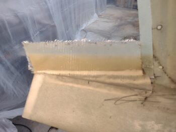
Another prerequisite task that needed to be completed before the actual microing up of the wings is the air gap on the outside front corner of top cowling, where it meets the wing.  I had an aha moment the other day as I was pondering how exactly I was going to do this, since it would be easier with the wings off, but I don’t want to spend the sheer time and effort to remove the wings and remount them just for this.  And clearly the wings need to be on during the finishing process to get them all even-steven and matched surface-wise with the strakes.

Here is the offending gap on the left (pic 1) and on the right (pic 2).
[In pic 1 note the crack in the wing flange at the corner about 1.5″ above the tip of the scribe… I discuss this in my next layup]

My eveel ingenious (that’s what I’m calling it… just go with it!) plan entailed simply floxing and glassing the strake’s cowl flange to the wing’s inside edge in situ, to then be cut after cure. To be clear, my plan involved layups on both the inside (underneath) and the topside, as I did in the pics below, but the wing is way thicker than the flange, so I’ll need to have good eyes-on and full access to work that… this should suffice for now:  some flox in the gap and a ply of BID, peel plied of course.

To keep my topics straight, I’m jumping ahead in time with the layups cured, and peel ply pulled.  Here we have my cut lines marked, which I will cut tomorrow after a good overnight cure.

Another layup task I completed in prep for finishing both the left wing and strake had a twofold purpose:  1) there was about an inch long crack on the wing-side flange at the very outboard edge/corner near the intersection of strake, top cowl and wing (closeup in pic above), and 2) when I set the wings in final position, the extra washers I placed on the left side wing bolts created a wider strake-wing intersection gap than the right side, and more than what I preferred.

So I laid up a single ply of BID, 1.5″ wide down the length and across the aft strake to wing intersection gap.  This will allow me to cover and reinforce the cracked wing flange while also reestablishing a thin gap “kerf” between strake and wing, since I still have to do the backside (underside) reinforcement layups on both strake and wing intersection lips after wing removal.

Again, jumping ahead hours later this is after cure when I pulled the peel ply (I will recut the left strake-to-wing intersection gap line tomorrow).

My final layup task for the day, again in prep for slathering up the left wing and winglet with micro, was to repair a small divot at the very top aft inboard edge of the left winglet.

This was simply a very thin area of UNI that somewhat aggressive sanding in prep for micro exposed.  You can see the spot where I cut away the dry, thin delam’d UNI where the light spot is from me reapplying micro, adding a very small patch of BID in the bare foam hole, then covering it with a ply of UNI.

On the aft 1/2″ TE depression I also added a postage stamp sized piece of BID both for transition at the depression for the overlying UNI (pic 1), but also to reinforce the aft top corner, which looked a bit rounded compared to its counterpart on the right wing.  Which all can be seen after I pulled the peel ply and razor trimmed the glass (pic 2).

Yes, it was quite a long, busy day… I pulled the bottom cowling off to allow me to get the wing root heat shields out to subsequently get the ailerons pulled off the wings [this pic also has the right wing top and inboard winglet final sanded and prepped for micro… which was my last task of the evening].

I then micro’d up the bottom surfaces of the ailerons.  Not shown is a pic where many hours later I cheese grated the micro-laden ailerons.

If you’re wondering why the right aileron (left in pic) is not fully covered in micro, it’s because when I skinned the bottom of the right wing many moons ago I followed some bad advice and immediately added some micro to the curing wing bottom skin.  Thus I have a layer of micro that has already been sanded down and the middle area is fine.  Just the overlapping BID on the forward edge and the trailing edge really needed it.

Also not shown was my using the orbital sanding to knock down the micro on the inboard side of the rudders about 80% to final.  Time was getting away from me and I wanted to knock down the micro before it got too hard to “comfortably” sand, which honestly will be job #1 tomorrow when I get into the shop (sanding micro’d surfaces).  Unfortunately it was very late, dark, and cold outside, so I sanded the rudders inside… yep, I broke the seal on getting dust everywhere!  Thankfully the plastic sheets are containing it in large measure so that only everything inside the plastic walls is covered in micro dust (sheesh).

My major goal for tomorrow is to micro up the right wing top and inboard winglet.

Moving forward…

Chapter 20/25 – Winglets on deck!

While I did do some more assessing and part mockups for the canopy latching hardware (more on that in the next day or two), my primary effort today was micro-finishing the outboard winglets.

I first got the left winglet prepped for micro, doing a good final sanding of any previous spots missed and then cleaning it for good micro adhesion.

I then whipped up and slathered on my micro/West 410 mix.  It took 12 pumps worth of West epoxy/hardener to cover the outboard left winglet.

As the left side outboard winglet micro cured, I then set my sights on the right outboard winglet and prepped it for final micro application as I had done on the left.  I have to split the pics between upper and lower since I can’t back up any farther to get these shots: my hand with the camera is up against the wall.

I then slathered on the micro on the outboard right winglet.  I used the same 12 pumps here, but I seemed to have slathered a little bit more towards the top (where I started) so I didn’t have quite the coverage on the lower side.  All good since I clearly have to add more micro on the inboard side of the winglet.

By this point the micro on the outboard left winglet had cured to its “green” stage and was ready for cheese-grating, which I spent a good 20 minutes knocking down all the higher ridges and higher areas.

I really do think this relatively short task is the trick to significantly lowering the time required for sanding after the micro fully cures (24-48 hours) in that you avoid wasting time sanding down the ridges and high spots and start at a much closer level to the final contour.

A few hours later I did the same on the outboard right winglet, with its micro application cured to its “green” stage, I cheese-grated it as well.  Although admittedly it was not as cured as I would have liked, and all the cheese-grating went fine, it was just a tad softer than I normally like it to be so it made removing the more-gummy shavings out of the cheese-grater a bit more of a time-consuming process.  However, it was quite late and I wanted to get the surface cheese grated prior to it curing to a much harder state.

And with that, I called it a night.

Over the next week I’ll be juggling between applying micro on different segments of the bird, cheese-grating and final sanding of these parts.  Later on after nearly all the parts are final sanded and cured, I’ll get to the epoxy wiping.

Pressing forward!

Chapter 18/20/25 – Shaving coconuts!

Today I was still embroiled in a lot of planning and assessing my path forward on various components on this bird that need some fairly expedited attention.

That being said, I also needed to get on with getting the micro finish (when I say that, I almost always mean about 4-5 part micro balloons plus a single part West 410 filler.  As our RV brethren have discovered, this makes sanding the micro finish infinitely easier with no noticeable loss in surface hardness) on this bird, so I slathered up the inside surfaces of the removed rudders with micro (pic 1) and then between 4-5 hours later I gave them a good working over with the cheese grater (pic 2).

During the cure time of the micro above I did some trial fits and ops test of my newly designed C4 canopy rod connector.  I trimmed down the inboard portion by 1/16″, but then ended up adding 0.02″ thickness back to it for the final version.  I plan on machining this fairly soon out of aluminum stock.

A bit later I prepped the outboard surfaces of the rudders for micro, including taping up the hinges and hidden bellhorn arms.

I also fired up my heat lamp and set a bondo knife on the 4 sides of the protective wire cage, one against each wire.  This is my method for always having a piping hot applicator that really helps “melt” the micro and make it WAY easier to apply to the glass surface.  I’ll use one for a minute or two max, then wipe it off, set it back on the heatlamp before grabbing the next one and using it for just a bit before the heat dissipates, then on to the next one.  Again, the heat is super, super critical in my opinion for getting a good flow of the micro onto the part.

I then slathered up the outboard sides of the rudders with micro.

Again, I took the cheese grater to the outboard micro on the rudders a few hours later.  At this stage it makes the micro look like either shredded coconut or mozzarella cheese.

And here’s the result.  I realize it’s a bit hard to tell with the distance of the camera and the white surface, but the high ridges are all knocked down and these will be ready for final sanding in the next day or two (at most).

Tomorrow I plan on continuing on with my micro-finishing of various parts, with the outboard winglets and ailerons on the short list of candidates.

Pressing forward!

Chapter 18/25 – Fighting for Finishing

First off, my sad tale of woe: my build work day was cut infinitely shorter as I chose to assist my friend in taking her daughter Trick-or-treating for Halloween.  It was good to see her having fun with Jess, her son and other kids, but being the crotchety curmudgeon that I am, I secretly wanted to be in the shop getting this plane prepped for finishing.

As I’ve noted, one prerequisite task that I need to do is to get the canopy latch system squared away in final configuration to in turn allow me to base subsequent micro fill actions on and around the canopy on the canopy’s final closed position.

As I told my buddy Dave B. in an email I just sent, it seems as if the gremlins got into various parts of my build and moved everything around just enough to cause a required corrective action from me.  This includes the canopy latching hardware in that I had to refer back to old blog posts and videos to figure how in the heck I had installed it all before… since it just wasn’t seeming to fit or operate as I once had it.

I determined that the C4 block (or bracket) —that the CL-2 latching pivot hooks connect to and also interconnects the tube segments from one CL-2 to the other, as well the front canopy latch handle— was causing the segment of the tube that transitions through the top of the pilot seatback to bind, as it was just too tight no matter if the CL-2 hook was mounted on the outboard or inboard side of the C4 block.

Now, I could attempt to create a totally separate end bracket to the aft tube & CL-2 hook and simply offset the connection that way to relieve any pressure, but since I don’t have one on hand that would require making one.  Since I have the aluminum on-hand, I figured I would just create a modified C4 interconnecting block and call it a day.  So after a few initial measurements, I spent about 10 minutes ginning one up in Fusion 360 CAD.

And 3D printed it…

And tried it out in situ in the airplane.

I noted that when actuating the tube forward of the pilot’s seat I was still getting a decent bit of friction.  I determined that the offset in my newly designed C4 interconnecting block needs to be offset about 0.06″ more inboard to allow free, friction-free travel of the interconnect tube.  I also need to make the inset just a hair wider/longer to ensure the hook has full freedom of forward/aft motion. So back to CAD for a re-tweak, which I’ll hit later tonight or first thing in the morning.

I was able to get the rudders off the bird and outside for a thorough sanding in prep for applying micro to the surface for finishing.  After sanding I hosed all the dust off with water and then did a quick wipe down to remove the excess water.  I set them aside to dry as I closed up shop to “enjoy” (ha!) some Trick-or-treating!

Happy Halloween!

(boo!)

Chapter 19/20 – Fairing flanges trimmed

Today was another assessment and planning day in large part, as I’m looking at all the tasks that need to be completed before I jump into micro-finishing the top areas of the airplane.

On the winglet-to-wing fairing aft wall layup I pulled the peel ply off each of the layups before marking up each side for trimming.

I then trimmed along the top edge where it meets up with the rudder on the left side…

as well as the right.

Here’s an inside look of the cured layup and the trimmed fairing wall, first on the left side (pic 1) and then the right side (pic 2).

I also did a fair bit of refamiliarizing myself with my canopy latch system to get that installed and final to determine my configuration in the finishing on and around the canopy.

Chapter 13/18/20 – Micro prereq tasks

After some thought on my work flow, I sat down this morning and updated my task list in prep for micro-finishing the remaining surfaces of this bird.

In prep to pull the rudders off the winglets to do the inside wing-winglet fairing flange layups, I noted on each winglet that the top trailing edge was proud of the rudder TE by about 0.02″.  Not much, but noticeable.

So I marked the top winglet TE and carefully evened it up with the rudder trailing edge using a straight sanding board.

Although I didn’t work the top gap between rudder and winglet, I did check in the regular plans and the high performance rudder plans to see if it called out the gap dimension.  I couldn’t find anything, so I’m planning to use the 1/16″ gap that is called for in the Roncz canard plans.  Although I didn’t widen the top rudder gaps at this point.

I did however take about 30 minutes to widen the aileron-to-wing side gaps to 1/8″ as per CP #43.

I removed the rudders in prep for the inside (technically “outboard”) winglet-wing intersection fairing vertical flange 2-ply BID layup.  The first ply just covers the added dry micro (filler here, micro for weight) in the “trench” at the intersecting edge of original winglet notch for the rudder and new fairing flange.

Note, if you look closely you can see that I also removed the prop spinner and propeller.

I used the Fein saw and Perma-Grit sanding tools to clean up the transition between the original winglet notch for the rudder and new fairing flange, first on the left (pic 1) and then the right (pic 2).

After cutting 2 plies of BID per side, and laying in drier micro in the intersection gap, I laid up the BID on the left fairing (pic 1) and the right (pic 2).

I then peel plied both layups… here is the left side peel plied.

I also noted that there is a slight difference in elevation between the winglet surface and the rudder near the top of the right rudder.  To bring the surface elevation back into alignment I added 2 plies of BID to the inside top rudder hinge pad.  I then peel plied the layup.  I’ll assess after it cures.

To ensure that the proper alignment for the inboard rudder edge is maintained with fairing vertical flange, I taped the bottom inside edges of the rudders with clear packing tape and then reinstalled the rudders.  I taped the rudders firmly into place, again to ensure that they sit perfectly flat against the inside fairing flange.

I also spent a good hour+ assessing the forward canopy fit with the aft nose/avionics cover and the forward fuselage near the longerons.  Clearly something was lost in translation when I did the final securing of the aft nose/avionics cover because there is wider gap between the front edge of the canopy skirt and the recessed glare shield portion of the aft nose cover.  The gap is more pronounced on the left side, being about 0.15″ wider than on the right.

In addition, I’m not overly thrilled with the original top curve of the longeron, since my canopy frame is more vertical (more French style) than the original lower, flatter, horizontal style canopy frame.  Since I’m getting ready to do the final finish on this bird, now is the time to remedy all these issues.

Besides filling the gap forward canopy skirt gap with the aft nose cover (and possibly reworking the glare shield aft raised rain blocking edge/seal), I will most likely fill the top longeron along the forward canopy edge to create a small flange and even up the flow between canopy and top fuselage (near the longeron).

Now, to do all this, the canopy needs to be set in its no-kidding final locked configuration.  This means ponying up and finishing the canopy latch assembly now —before micro-finishing— versus later as I was thinking.

Yep, still pressing forward!

Major Project Update Video

Today I finished editing and posting my 2nd-to-Final Major Project Update video on YouTube.  It’s a rather long video, probably the longest video I’ve made, but it’s fairly comprehensive in detail on the engine install and other completed tasks.

Here’s the video:

With the video knocked out, tomorrow I plan on getting back onto the actual build.

Pressing forward!

Chapter 23 – Major Project Update Prep

I’ve spent the last few days prepping for my major project update video.

Besides giving the workshop a good cleaning and organizing, I also mounted the canard, canopy, aft nose/ avionics cover and nose hatch door.  I also put the front seat cushions and temporarily taped the headrest pads in place.

I also pulled tape off the canopy, wingtip NAV/strobe lights and a number of other places.

I vacuumed out the engine compartment and wiped down a good bit of the engine components.

I also mounted the wheel pants (airing up the tires first), RAM air scoop and prop spinner.

As you can see in the background, I also hung sheets of plastic around the bird to mitigate the dust from getting everywhere when I sand the micro finish to contour on all the top surfaces.

Although I did record a couple segments of the major project update video last night, I knocked out the remainder of the video this evening.

I then got to work editing the video.

Tomorrow I plan on having the video edited, complete and uploaded to YouTube, at which time I’ll get back to work on the plane.

Chapter 23/24/25 – Punch list work

This blog post covers that last few days.  I’ll start off by noting that yesterday I was unexpectedly asked by my friend Shelly to take her to an appointment down in Wilmington to remove stitches from her recent foot operation.  Needless to say, that pretty much wiped out my shop time for any tasks other than some general cleanup and hanging some dust-retaining plastic for my upcoming micro-finishing ops.

Rewinding a few days: I wanted to get some layups knocked out as I’ve got a few iterative rounds of final fitting of the top cowl front edge to the turtledeck coming up.  My original plan for the right side where the top cowl oil cans between 2 CAMLOCs, leaving the interfacing turtledeck surface low, was to build up the turtledeck somehow…. but then I decided to underfill the top cowling front edge from inside to fill in the air gap and simply sand down the outer surface of the top cowling level with the turtledeck.  Again, this will almost certainly be an iterative process, but in the end I think it will work much better than adding more material to the turtledeck.

I started with 3 stepped plies of carbon fiber on the inside right front edge of the top cowling.  I realized when I started to pull the peel ply that I had failed to grab some pics, so here is peel ply coming off (pic 1) and after cure with the peel ply off and CAMLOC holes clear again (pic 2).

I started the process to a much lesser degree on the left side as well, with a long single ply of CF to help fill in a slight gap, then another semi-circular ply on the inboard side (right in pics below).  Again, carbon fiber layup with peel ply (pic 1) and after cure with the peel ply removed, razor trimmed and CAMLOC holes clear (pic 2).

I had a little bit of epoxy left over in my cup, which as you probably know by now I hate to waste, so I did a quick 2-ply carbon fiber layup for the bottom lip of a GIB seatback hole cover that I will construct over time.  Here it is with peel ply on the underside and topside of the layup.

And then after cure with the peel ply removed, but not yet trimmed to shape.

Again, I started hanging plastic in prep for all the dust I’m going to create when micro-finishing the top of the bird in prep for painting.  I started by specifically hanging the plastic in the areas around the nose of the plane that would be hard to do with the canard in place.

Oh, by the way, note that I pulled the canard out of the house and installed it on the bird.

Also clearly visible is the aft nose/avionics cover and recently sanded nose hatch door in place.

Nothing is ever accomplished without sacrifice, and for me I spent well over half an hour looking for the baggie with all the aft nose/avionics cover hardware.  Even then, about half the CAMLOCs were missing so I spent nearly an hour in trial and error fitting of CAMLOCs to “finalize” fit (not all, since paint may require a few CAMLOC size changes).  To avoid playing the ever-so-fun “find me if you can” game, I created an Aft Nose/Avionics Cover Hardware Card like I have for both cowlings, RAM air scoop and wheel pants.

Besides finalizing my task list for such things as the aft nose/avionics cover, nose hatch cover, canard, elevators, etc., my installing of all these on the bird is a final pre-micro finish hurrah for one of the final major project update videos I’m about to record.  This is the first time during this build that this airplane will have all the major components (minus panel) installed together in essentially a “flight ready” status… and I want to capture it in the video.  Yes, I admit it’s for bragging rights, motivational fun and build status documentation all in one.

Speaking of documentation, I had compiled a video while I was constructing the exhaust pipe brackets and was waiting for James to do the final welding on the brackets before I posted the video.  However, James is neck deep in moving his business operations to a brand new just-built shop, and I know he’s super busy.  I wanted to get the exhaust pipe bracket video out before I post the major project update video so the sequencing wouldn’t be weird or out of order, so I finalized the exhaust pipe bracket video and uploaded it.  Here it is.

And with that, I’m going to get back to my shop cleanup and final task prep for my major project update video.  Once I’m done with the video, I’m pulling and bagging the engine and then rolling into micro-finishing the fuselage, strakes, wings and winglets.

Chapter 23 – Oil door wire clip

As I mentioned in yesterday’s post, Jess and I went out of town for a good portion of the day today, so I obviously didn’t get much done in the shop.

That being said, I did get the bottom cowling removed and then re-installed the exhaust pipe brackets in prep for my upcoming major project update video.

I also pulled off the taped metal block that I used to weigh down the carbon fiber clip layup inside the top cowling that will secure the wire push-pull handle that opens and secures the oil check door.

Here we have the cured carbon fiber clip on the inside of the top cowling, still yet to have the peel ply pulled or clip trimmed to shape.

After getting the clip layup cleaned up, I figured the easiest way to describe it in action was to simply show it in operation.  Here’s a short clip (pardon the pun) of it in action.

As I noted in the video description, this clip will keep the oil check door securing wire in place during flight to ensure that 1) the door stays closed and 2) the wire doesn’t work its way out of the cowling to interfere with the prop [note: it shouldn’t due to its length being intentionally too short to enter the prop arc].

Tomorrow I plan on getting a few more tasks out of the way, again, in prep for my major update video…. after which I’ll get to micro finishing the top side of the bird.