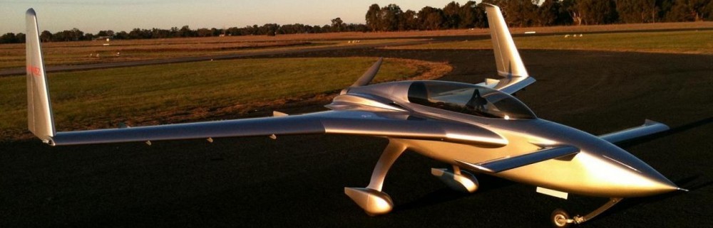
Chapter 25 – Wings/winglets paint ready

I had a good, in-depth discussion with Shane Banquer yesterday regarding my baggage pods that he has to make molds from, as well as a number of other various points regarding painting.

We discussed the pros and cons of painting the aileron and rudder hinges, at which time I told Shane I was thinking about crafting an insert that would slide into the hinge notches to protect both the hinge pin holes and interfacing edges from getting paint applied in or on.  Well, here is the result of that discussion: a test insert for painting the hinges, IF I decide to go that route.

I then spent a good bit of time sanding the epoxy wiped right wing leading edge, first with 80 grit on my orbital to knock it down a good bit.  Then I used a 30″ board to wet sand it with 150 grit.  I’m happy to report at this point, that besides a final scuffing and cleanup, the right wing/aileron (top) and winglet/rudder is ready for primer and paint.

I spent another good hour working primarily the left aileron’s middle hinge configuration and internal hinge clearance, which once completed eliminated that awful middle hinge squawking.

As I assessed the final left aileron install and configuration, I decided I wasn’t happen with the middle hinge gap with the wing notch it sits in… it was too big forward of the hinge and wasn’t tight like all the other (at this point) hinge notch gaps (sorry, no ‘before’ pic).  I realized if I didn’t fix it now that I would regret it later on… so I removed the aileron, temporarily attached a taped-up stir stick to the underside edge of the notch, and slathered on some flox that I whipped up using MGS 285 epoxy (pic 1).  A few hours later I removed the taped stir stick to reveal the floxed edge on its own (pic 2).

I did essentially this same process on the left aileron inboard hinge notch and the left rudder bottom hinge notch as well, but didn’t document either of those… so I thought I would show you what I’m up to here.  I did a rough sand of the added flox to knock down the high spots (pic 1) and then marked the “cut to” line just a hair aft of the actual edge line I want (pic 2).

I cut the flox edge up to the marked line using the “Fein” saw (pic 1) before finalizing the sanding and shaping of the left aileron middle hinge added flox edge (pic 2).

A little while later I reinstalled the left aileron, and here’s what it looks like.  Much, much better… albeit I still may add a scooch of micro now on the inboard (right) side to close up THAT gap a hair (yes, unending!).

At this point it was finally time to trim the wing-to-winglet fairings respective trailing edges.  To have the TEs perpendicular to aircraft CL I ran a string across the trailing edge of the rudders just where they met the fairing wall aft top edge (I’ll note that the prerequisite task to do this was sanding down the epoxy wiped outboard front corner of the right rudder, then installing the rudder back into place).

I then realized that to get a better cut mark I needed the string to be below the fairing, so repositioned it on each side.  I then marked the left fairing TE for cutting (pic 1) and the right fairing as well (pic 2).

I then took a dinner break to spend a few hours with Jess.

Upon my return to the shop I knocked out cutting the aft edge of the left winglet intersection fairing (pic 1) and the right fairing’s aft edge too (pic 2).

Here we have a couple more representative shots of the cut aft edge of the left winglet intersection fairing.

Again, I’m even more happy to report that the left wing/aileron (top) and winglet/rudder meet my minimum requirements for primer and paint!

Tomorrow I’ll finish up any minor tasks on the wings, winglets and strakes as I press on with the top and bottom cowling paint prep, as well as the centerline fuselage and canopy interface finalization for micro finishing.

Chapter 3/25 – Knockin’ down the list

I started out today by spending a couple hours at the airport with Guy Williams putting the new wing lift jacks to the test… which they passed splendidly.  I do plan on modifying them with some type of positive stop to not rely solely on the bottle jack for keeping the wing/strake elevated, but that’s a minor issue.

Again, Guy is dealing with a warped main gear leg on the right side, almost certainly caused from braking heat damage.  He’s assessing his options for repairing it.

Back in my shop, I started by knocking down the right winglet LE cured epoxy wipes with an 80 grit disc on the orbital sander.

I then used a long sanding board to sand down another round of micro/West 410 that I had added to the initial added fill to the right wing leading edge.  I’ll note that the LE still isn’t laser straight, but it’s much, much straighter and will be very close to spot on straight once I add a few rounds of primer and sand those down.

With sanding complete, I epoxy wiped the right wing leading edge with 4 rounds.

Along with the right wing leading edge above, I also epoxy wiped the outboard right rudder… which I had sanded down some micro/West 410 (leftover from the wing LE added fill) that I added to this front lower corner on the outboard side of the right rudder.  This very minor add results in this corner matching the surface level of the matching/interfacing corner of the winglet.

I’m also very happy to report that over the last few days I dialed in and finalized the sanding/shaping/contouring in and around the areas of the intersection of the winglet leading edge to the wing… on both left and right sides.  Both of which were recently covered with black guide coat.  I may have some very minor tweaking to do (not surprisingly) after primer is applied, but those areas are looking pretty darn good now.

In between epoxy wipes, I then got around to micro’ing up the top cowling. My main target here was the front outboard corners to allow me to integrate them with the strake micro fill surfaces.  As you can see I also got the center backbone depression and top aft edge micro’d up as well.  I still need to do add micro on the aft vertical areas and the undersides of the “trailing edges.”

In the same fashion as the right rudder above, I finished wet sanding the epoxy wiped added micro to the front lower outboard corner of the left rudder as well, before installing it back on the left winglet.

I then wet sanded both sides of the rudder across the seams onto the winglet as well, to get the surface levels as evenly matched as possible.  Here we have the left rudder final install, micro finished, ready for primer and paint on the outboard side (pic 1) and the inboard side (pic 2). [Final configuration/install of the left winglet top video camera mount coming up soon]

Thankfully the last couple of days have been warmer and I haven’t needed to utilize the Kerosene torpedo heaters, but I wanted to note that I broke out my CO detector to ensure I wasn’t gassing myself with carbon monoxide in the shop by firing up those heaters.  So far so good, and no sign of any CO.  Honestly, I didn’t expect any because the consumption burn rate on Kerosene is reportedly very complete.

My biggest issue at the moment, and my final task of the evening (no pics), is the reinstallation and configuration of the left aileron back onto the left wing.  In my constant rush to get stuff done, I believe that I allowed too much epoxy to fill in the aileron hinge screw holes in the wing during its epoxy wiping.  I figured the surrounding/existing holes would simply allow me to redrill through the cured epoxy and thought nothing of it.

Well, apparently the cured epoxy caused some slight offsets during the redrilling of those hinge screw holes, because I haven’t been able to get the left aileron installed back into its pre-epoxy wipe position… and I’m having some clear squawking from the middle hinge with the aileron installed. Bottom line is it needs some tweaking and TLC to get back to good.

With that said, I’m still getting closer to paint every day… pressing forward!

Chapter 3/24 – Wing lift jacks built

Today was the first decently warm day we’ve had since Thanksgiving, so I decided it was time to knock out an outdoor task primarily for my Long-EZ buddy, Guy Williams. As I noted, the right main gear strut on his Long-EZ is having some gear issues as a result of heat induced at some point by the brakes.  In essence, the camber of both wheels have the tops both leaning towards the left, when they both should have the wheel tops more outboard than the bottom of the wheels.  Yep, something is askew!

I ran down to Lowe’s hardware and bought a sheet of 3/4″ plywood (buried in pic below) to construct the wing lift jacks, and also picked up the first round of lumber for constructing the in-shop post cure heat room/paint booth.

Back home I unloaded all the other stuff by quickly crossloading it to my nearby utility trailer.

With my 3/4″ sheet of plywood now unburdened by what had been (pic 1), I cut the sheet into 3 pieces: two for the jack uprights and the smaller piece for the jack bases (pic 2).

There are four (4) uprights to each lift jack, which I cut out of each of the 2 larger 3/4″ plywood pieces on the table saw.

With the remaining piece of 3/4″ plywood, I cut 2 bottom bases out of it: about 20″ x 20″ (pic 1), and then 2 smaller top cap pieces 8.5″ x 9″ (pic 2).

I then dug through my scrap pile under the carport to grab two 4x4s and cut those at ~30″ long (pic 1).  I then made all the initial 5″ wide x 12″ high notches in the uprights (upside down in pic 2).

I then marked an angled line on each upright and cut each one with my Skil saw.

Here we have the angled cut lines complete for one set of uprights, with the next set getting cut next.

A couple of hours later, and Voila!  A set of 2 fully functioning and operational wing lift jacks!

I of course tested the height using my Long-EZ as the test subject.  Looks like these dogs will hunt!

I spoke with Guy and we plan on doing a live ops check with these wing lift jacks in a couple days.

I’ll note one other topic that I was remiss in communicating in my last post: a squirrel war report.  Apparently, with the weather having gotten quite cold, the squirrels did another full frontal assault in trying to nest in my shop.  Well, when I dismantled their latest rounds of nest-building they went ballistic!  The last couple of days I’ve walked into downed lights, entire light banks out of commission, speaker wires cut, CAT-5 cables cut, Bluetooth puck cables cut, Wi-Fi router power cable destroyed, etc.  I mean they really wanted some payback for their destroyed nests.

Well, after Day 2 of their rampage I had enough.  I spent over $50 on mothballs and poison rodent food and stuffed the mothball packs into their ingress and egress points, as well as in the 3 nest areas that I know of.  It took me well over an hour to get the lights back online… each day.  The other stuff is still inop, but a couple of days later now and I’ve seen zero signs of the squirrels.

So, lesson learned… keep deploying fresh mothballs every so often to keep those sadistic little bastards out of the shop!

Chapter 25 – Checking in…

Steady work going on over the last couple of days on a myriad of smallish tasks in prep of getting this bird ready for post cure and then paint.

I got the right winglet leading edge added micro/West 410 fill sanded down and then epoxy wiped with 4 coats of West epoxy.  The right winglet LE isn’t as razor straight as the left side, but it’s pretty darn close and I’m not going to spend a ton more of time on it… to get it perfectly straight would require another round of fill and I just don’t think it’s worth it.  I want this plane flying, not passing straight edge inspections on leading edges down to thousands of an inch!

Now, that being said there is a level of straightness that I do want, and the leading edge of the right wing is currently not cutting the mustard.  So I sanded it down and slathered on West 410/micro to get it significantly straighter than it is now.  I’ll sand it down tomorrow and epoxy wipe it as I did the right winglet (and left wing too).

I initially sanded the epoxy wiped outboard left wing and outboard left winglet, knocking down the epoxy with 80 grit on the orbital sander.  I then spent a good bit of time working the lower front corner interface and surface level betwixt winglet and rudder.

I think with some minor sanding of some added West 410/micro fill (scraps from right wing LE) on the very front lower corner of the rudder it should have a nice transition from the winglet corner level.  Once I get the lower corner dialed in, I’ll then wet sand across the rudder-winglet interface seams —both inboard & outboard sides— to ensure those are nice and level with each other.

I did a bunch of other odd tasks as well, along with a good bit of assessing on the inboard hinge on the left aileron… that looks to need some tweaking and I’ll report on that as soon as I get a final assessment of what is required.

Regardless, my goal is to wrap up all the wing/aileron, winglet/rudder, and strake micro-finishing prep for primer and paint and move on to top cowl, turtledeck, longerons, and nose micro-finishing.

Pressing forward!

Chapter 25 – Finishing prep… and prep

Today, before I changed into my shop clothes I headed downtown to Harbor Freight to pick up a couple of bottle jacks to use in some wooden wing lift/jack stands to allow lifting one wing or both wings up at the same time.  Sometimes on these birds you want to be able to work on the main gear, brakes, wheels, etc. without using a main gear leg as the jacking point.

I had to buy these bottle jacks today since they were on sale, making them cheaper than the significantly smaller (but still would have worked) 4 ton bottle jacks.

Again, my timeline in regards to working these stands now is simply because my buddy Guy Williams needs them to repair his heat warped gear leg on his Long-EZ.  And of course I wouldn’t be surprised if I need them at some in the near future as well (hopefully not for the same reason!).

I also rounded up the original pic that Steve Rothert posted of his stand, and this was the best (and cheapest) of all the ones I saw on the COBA forum… and there were plenty examples to be sure.

Back in the shop I removed and installed the left aileron a couple times as I dialed in the wing’s inboard aileron pocket hinge notch trailing edge.  After some minor finagling and sanding I got it where it allowed me to install the aileron in place, just without the unsightly wide, off-angle gap.

I live fairly near the high school and my friend’s daughter, my now not-so-little buddy, has been experiencing some bullying issues on her school bus.  The past couple weeks she’s been walking to my house and hanging out for 2-3 hours until her mom can pick her up after work.  Well, she helped me do the final wet sanding of wing and aileron at the seams between the two, to ensure the surfaces are level with each other.

After sanding down the West 410/micro added fill on the outboard end and leading edge of the left wing, I then whipped up some West epoxy with 205 fast hardener to do the first round of epoxy wipes on the sanded added wing filler (pic 1).

I installed the left rudder and assessed some issues that needed worked, the main area being the thick micro fill on the outboard winglet at the bottom front corner intersection with the rudder.  There was at least a good 0.1″ jut out of the winglet edge at this corner vs the rudder, so I removed the rudder and aggressively sanded this corner but also kept watchful eye on ensuring it flowed with the remaining winglet surface (pic 2).  There are some tricky contours in play on these outboard winglets.  My sanding left a patch of bare micro, which in itself isn’t an issue, it’s the hard edge between it and the surrounding epoxy wiped surface that I wanted to reestablish a smooth transition.  Thus I also epoxy wiped the area I sanded at the bottom rudder corner, along with the wing.

These pics are at the end of the evening, with 3 total coats of epoxy wipes.  Also note the gap between the winglet and rudder front edge was a little too wide just below the bottom hinge, so I added a flocro edge both on the winglet side and the rudder side.

Over on the right side I sanded down the leading edge of the right winglet to allow me to add West 410/micro to it.  Again, eyeballing it the winglet LE looked straight, but with a straight edge against it you could see some peaks and valleys, around 0.1″ in variance.  Tomorrow I’ll sand it straight and re-epoxy wipe the LE.  I also plan on doing the same process for the right wing LE, which is pretty much the same story.

I closed out the major task portion of the evening by wet sanding the left strake top and leading edge, as well as the RAM air inlet on the leading edge, with 150 grit.  Inside the air inlet was some rough spots so I whipped up some West 410 and applied it on the inner inlet tube [note red Kerosene heater #2 in lower left corner: specifically purchased for the upcoming post cure].

I also wet sanded all the smaller areas I epoxy wiped yesterday, like the right wing video camera threaded inserts, right wing TE spot, etc.

I had padded the mold for my top left winglet video camera mount for the layup, but I may have overdone it for the 1/8″ thick internal protective foam rubber padding I had planned on using… so as not to scratch up the paint on the winglet top.

Again, the weather has been quite chilly, so I fired up the Kerosene heater to run for about 10 minutes to get the shop nice and toasty before I locked up for the evening. While the heater was running I grabbed some 1/8″ thick cardboard and taped it to the top of the left winglet.  I then put the glassed video camera mounting base cap onto the winglet.  It fit ok, but not overly snug as I would prefer… so more finagling will be in the works for this guy.  I may punt and simply go with 1/4″ (vs 1/8″) foam padding.  We’ll see.

It was again a late evening, so with the shop given it’s last blast of hot air for the night, I locked ‘er up and headed inside.

Moving forward…

Chapter 24/25 – More camera mounts!

I started in on adding tape and even some cardboard to the top of the left winglet for what will be yet another video camera mount.  I added the cardboard since I will be using a rubber pad on the inside of the mount to ensure I don’t damage the paint on the winglet.  I’ll use that same rubber on the wing and right strake video camera mounts as well.

I then cut out 3 plies of BID (off the roll… haven’t done that in a while) and 2 plies of UNI (from leftover scraps) to use the same layup schedule I have on the other video camera mounts: BID-UNI-BID-UNI-BID.

I wetted out some peel ply first before laying up the 5 plies of glass, and then topped that off with some peel ply (pic 1).  Many hours later after the layup was about 90% cured, I pulled the top peel ply layer off (pic 2).

A little while later I pulled the entire layup off the left winglet top (pic 1) and then pulled the interior peel ply and simply cut the un-epoxied glass off around the edges (pic 2).

I then set the video camera mount back onto the left winglet to do its final cure overnight.

I had to run downtown for some Kerosene at a gas station that I found where I could simply pump it into a container.  I ended up going out for a quick bite with Jess, and while waiting for our food to arrive I got a call from my local canardian buddy Guy Williams.  He has heat damage to one of his Long-EZ gear legs and needs to jack up his bird to get the gear free hanging.

I had done some research on the COBA forum a week or two ago noting Steve Rothert’s roll-your-own jack stand design, before making a quick CAD model of what I remembered his design to be tonight.  I then sent these renderings to Guy to show him what we could do to help get his bird fixed and back in the air.

Back in the shop I did a A LOT of sanding on the front outboard corner of the left wing to knock down a couple of high spots, and deal with some low spot areas as well (partly my doing from my sanding down this area to knock the wingtip micro fill down a good bit).  The end result was that I had a slight low area that I decided to fill with West 410.  This is the area that I showed you had black guide coat sprayed on it in the past post.

Another problem area that I sprayed black guide coat on was over on the right wing, in a swath from the TE forward to just outboard of the wing bolt access hole.  As on the left wing above, I sanded this down for a good 20-30 minutes.  You’ll note some guide coat still showing in spots that are VERY shallow, but not high enough to get sanded off. At this point I’m going to leave some low spots that should get filled in with the first few rounds of epoxy primer that I will shoot, and then another round or two of high build 2K primer after that.  If need be, on TOP of the epoxy primer I’ll fill whatever divots or imperfections need filled.

I’ll note that just above and outboard of the wing bolt access hole I broke through back into original raw micro.  I hit this with a round of epoxy wipes as I was doing those below.

Yep, as I mixed up some West epoxy with fast hardener for the 410 fill I did on the left wing above, I used a bit of that raw epoxy to some epoxy wipes on the right wing video camera threaded inserts, a spot on the right wing outboard TE, a bit on the inboard corner of the right aileron, outboard right rudder, outboard left winglet, etc.

I then did another round of epoxy wipes about an hour later for another coat.

I wet sanded the entire top of the left wing and leading edge, as well as the left aileron top and both sides of the left rudder with 150 grit.  I then temp installed the left aileron.

I’ll note that cleaning up the hinges on the left aileron to put the other side hinge halves in place took WAY longer than I expected, and I spent nearly an hour getting those fine tuned and installed.

Now, pre-epoxy wipes I didn’t like the gap of the inboard left aileron hinge notch, so I filled it in with a small edge of flox, and then some micro/West 410 over that to finalize the fill on the very edge of the hinge notch, just underneath the screws in the pic below.

However, on the outboard/left side it’s a tad too thick/wide still and is not allowing the hinge to seat all the way forward.  This will be a simple fix of sanding it down a little.  Just wanted to show yet another task that I didn’t really report on earlier (I did the same thing on the bottom hinge of the left rudder).

I then ended the evening by wet sanding the right strake top and leading edge with 150 grit.  It turned out pretty nice if I do say so myself.

Tomorrow I will continue pressing forward with my primer & paint prepping tasks!

Chapter 25 – Cold: the new challenge

Yes, I’m guessing pretty much across the U.S. the cold weather rolled in with a vengeance just after Thanksgiving.  Thank God for Black Friday, since I was able to nab a myriad of tools and supplies for my main upcoming tasks: a post cure of all the major airplane components, and then painting.

One Black Friday sale I availed myself to was this torpedo heater from Tractor Supply.  I’ve had it for a couple of days now, and finally got around to filling ‘er with Kerosene and firing it up.  It definitely does its job… I can say that!  Moreover, this is a critical piece of equipment for my upcoming post cure.

I’ve also spent the last couple of days doing a deep dive on exactly what I need for the post cure, and then the paint following that.  Again, I’ve hit a number of Black Friday sales to pick up a couple extra paint guns and a slew of painting supplies while it was all on sale.

Today I got back to building on the bird for a good bit.  My main task was mounting the right rudder and aileron that I wet sanded with 150 grit sandpaper (last night).  I then spent a good bit of time sanding both the aileron and wing across the intersection seams, as well as the rudder with the winglet (on both sides).  I’m very pleased with both the gaps between aileron and wing, and rudder and winglet… as well as the surface level where they meet.

You may note the black paint I’ve sprayed as a guide coat in some problem areas, which again I did last night.  I’ll sand these down most likely tomorrow to have all the surfaces ready for primer.

I also finished prepping the right wing video camera mounting threaded insert hard points (yes, that I worked on last night!) for a few rounds of epoxy wipes to ensure they are nice and sealed for primer and paint.  Again, note the applied guide coat for another problem area that needs worked.

I then spent a good little bit wet sanding both sides of the left rudder with 150 grit sandpaper.  I focused on the left winglet (only) to have it close to very final shape to then use it as a mold for the top of left winglet video camera mount.

I didn’t get a shot of it, but I spent the remainder of my evening taping up the top of the left winglet and cutting glass in prep for the top of left winglet video camera mount that I plan on laying up first thing tomorrow (so I can monitor the kerosene torpedo heater).  And with that, I called it a night.

Still pressing forward!

Chapter 24/25 – Clearing the Queue!

Or trying to anyway!

Again, since this is during the Thanksgiving holiday, this post covers the last couple of days.  I didn’t get a ton done, but I did make a good little dent.

I started off with making yet another threaded insert —ala baggage pod style— for yet another video camera mount.  This one will be on the very top edge of the left winglet, which has the 1″ added internal foam cap that just happens to be the denser PVC foam. I did this when I constructed the winglets simply because I had a piece of foam that size sitting there and decided to use it.  Well, many years later that denser foam should help in adding some oomph to the pair of threaded inserts going into it… or not.  Either way, that’s what’s going on.

I’ll note that like the other pair of threaded inserts I’ve recently installed, the first one is 6061 aluminum, while the one I just made (nearest camera) is 2024 aluminum.

Yet another small victory I attained was drilling out the 12 year old Saran wrap stuffed into the threaded inserts on the inboard leading edge of the right wing.  These are actually for the baggage pods and it was nice that they cleaned up so easily.

To ensure these baggage pod hardpoints were good to go, I threaded a screw into each one.  Ahh, they work as designed!

Starting late in the afternoon today (Thanksgiving) I got busy knocking down the cured epoxy wipes on the left wing, winglet and aileron top (not the rudder… yet).

Yep, I spent over 3 hours with my trusty orbital sander in hand, with 80 grit discs (a few of them!) to knock down and level out the finish on the left wing, winglet and aileron top.  In fact, it took me over an hour just to finish both sides of the winglet.

I’ve got a good bit of running around tomorrow, and the weather is forecasted to start getting much cooler, but I will adjust as necessary and push forward as best possible!

Chapter 25 – My learning curve

A funny thing happened while I was building my Long-EZ, or technically micro-finishing this bird, in that I realized that except for the canard many moons ago, I have not really dealt with LEADING EDGES in my previous micro-finishing endeavors.

Yes, we all know what happens when we assume things, and beyond using the longboard on my leading edges initially, I really didn’t give them a lot of thought after that since they looked straight.  Again, that assumption thing!

Well, out of curiosity I checked my leading edges on my left wing and winglet.  Wow. What I had assumed was straight was far from it.  The wing leading edge looked ok in merely casually looking at it, but with a closer look it had some significant peaks and valleys going on.  The winglet LE wasn’t as bad, but still not as razor straight as I’d want (especially for a “show bird” as my fellow builder <singular!> likes to claim… ha!).

At this point I would like to highlight that unlike most of my current building buddies, I was not able to avail myself (due to scheduling and relocating overseas) the services of Mr. Stephen James in acquiring his Eureka CNC wing cores. That’s right, although I bought my wing cores from Feather Light, they were still cut the good ol fashioned way: with hot wire and templates.  e.g. not perfectly straight CNC edges!

So whipping up some micro/West 410 was in order, which I slathered on the winglet leading edge last night.  This morning I started knocking it down and didn’t stop until I got it down quite a ways.  Obviously with some added filler on the front, it was going to cause a few gaps where it feathered back onto the existing winglet/fill… so a bit more filler was required to transition those gaps.

Thankfully the wing leading edge added micro-fill, after knocking it down, did not require any extra fill.  The wing LE is pretty darn straight now up until the outboard 18″, which has about a 0.08″ dip until the very tip of the wing, due to the added glass for the wingtip.  Now, I plan on adding a LE “disrupting” landing/WigWag light in this area, so I think that will disrupt the slight dip, so I’m not worrying about it.

If you’re wondering about the already epoxy-wiped right wing and winglet, well, yep… I will be reworking those leading edges as well.  The winglet I’ll do in the next few days.  For the wing I decided to do it with the wing off, LE up, as I’m prepping the right wing for final primer and paint (and installing the LE light on that side as well).

Ok, so for any builder reading this pre-wing/winglet finishing, the trick I now know (in retrospect) is to dial in the straightness of the leading edges FIRST, then contour the rest of the airfoil from there.  I probably read this somewhere in my myriad of research, but clearly missed putting it into application.

Another issue I found that I needed to deal with is the forward side of the left wing end, terminating at the front corner wing tip (AKA Nav/strobe light base).  The micro out here is piled up significantly more than on the right wing.  Clearly we pile the micro up when applying it to then give us a straight, smooth surface… but there is a balance.

First, obliteration of the natural shape of the wing is not part of the process, IMO.  And out here this piled up micro was doing just that.  Again, especially compared to the right wing.  Moreover, our Long-EZ wings have a washout, so although the LE is straight, there is an overall downward curve/twist to the wing as it goes outboard.  And I felt that I was affecting this washout with all my “straight” micro piled up.

Finally, looking at the wingtip from the outboard end (pic 1) one could see the micro piled up on top to the point that the Nav/strobe was no longer centered on the wingtip, but rather looked low because it was, with more than required micro atop the wing in this area.  Thus, I marked up the forward area of the outboard left wing to knock down the micro a good bit (pic 2).

I have to say I’ve read a number of accounts of builders using long sanding blocks/sticks to ensure the surface is even all the way down the line, and I think there is a good bit of area on the wing that is conducive to this approach. I too of course employed the classic “stick of pain,” long sanding board.  But I also think these wings have some natural (or unnatural really) curves that require the shorter 30″ or 18″ boards to blend in the overall contour in those areas… which is primarily each end of the wing: inboard 2-3′ near the cowling and outboard 2-3′ near the winglet.

All that stated to say this wing end is one of those areas (again, IMO).  My goal here was to knock the surface down approximately 0.1” CAREFULLY to 1) match the right wing, 2) find, ‘allow’ and maintain natural wing washout, 3) have my Nav/strobe light at least somewhat centered on the wing end.

Yes, the micro is still piled a bit higher than I had planned for, right where the wing extension dives into the outboard base of the winglet (pic below).

If looking from the front this matches the inboard height/level of the wing surface intersecting the base of the winglet.  In using a sanding block to knock down this forward area, I of course feathered in the entire area to get a nice transition.  This inboard spot of the wing intersecting the winglet flowed even with the rest of the wing… and to force a reduction in height in such a small area is asking for trouble in my book, given that it could knock out the nice even flow of the entire area and result in a mismatching low spot.

Best to swallow the little frog in regards to my Nav/strobe light position —which is noticeably better— and press forward in getting this bird finished.  [Little frog is a reference to wilderness survival: eat little frogs for protein… easier to gulp down than a big ‘ol frog staring you in the face.  Also pertains to a stock trade going bad: take the little loss (little frog) vs merely hoping as your stock falls off a cliff and losses climb (big frog). But I digress!]

With all my leading edge and wing tip shaping shenanigans under my belt, I started another marathon round of epoxy wipes on the left wing and winglet.

And a mere 6 hours later I was finished, replete with all the protective tape boarders removed and nothing left but to allow the 5 coats of epoxy to cure.

As I did on the right side, I of course also epoxy wiped the left aileron top and both sides of the left rudder.

Another shot of the epoxy wiped left aileron top and rudder (both sides).  Here I only used 4 coats of epoxy before calling these good.

Needless to say, given the time of year and weather situation at hand, I’m very pleased to have the major aircraft components (wings, winglets and strakes) micro-finished and epoxy wiped.  I still need to micro-fill and epoxy wipe the outboard 3′ of the wing bottoms and inboard bottom winglet, as well as the top of the nose, longerons and turtledeck.  And finally, the elevators need to be completed as well.  Thankfully on all those I can focus heaters and heat lamps to keep localized temps elevated to acceptable curing levels.

I expect tomorrow to be a light build day, and the day after is Thanksgiving, so probably even less building then.  Happy Thanksgiving all!

Chapter 24/25 – Pre-epoxy wipe push

Although the majority of my efforts —as felt by my shoulders and back!— were on performing the final sanding and shaping of the left wing, winglet, rudder and aileron, most all of the pics I have are in regards to knocking out the video camera mounts’ threaded inserts install.

Clearly the video camera mount that I am most concerned about is for the left wing, since I want to have both threaded inserts floxed/micro’d in place prior to my epoxy-wiping the wing surface.  That being said, I pressed forward with other video camera mounts since I was currently performing the task on the left wing.  10 minutes cutting glass, doing a small 5-ply layup or prepping a threaded insert/hole for floxing doesn’t add a whole heck of a lot of time in the grand scheme of things.

Here we have the left wing video camera mount with the front threaded insert installed and the aft 6061 insert/hole ready for install (pic 1). Again, I installed the threaded inserts one at a time due to the curvature of the wing and wanting to ensure they were configured/spaced correctly.  I was a step in tow on the right wing, following suit of the left side, with the forward hole and threaded 7075 insert prepped for flox/micro (pic 2).

And an “action” shot of the left side aft threaded insert floxed/micro’d in place (pic 1) while the right side’s front 7075 threaded insert floxed/micro’d in place (pic 2).

I did a number of micro/West 410 refills on the left wing and winglet, with a decent sized one on the aileron as well.  Here’s a representative shot of some West 410 filler on the outboard wing/winglet intersection (just above the Nav/Strobe light position) and some fills on the lower aft winglet.

In hindsight, I guess I could have grabbed some shots of both the rudder and aileron installed, since today is the first time since I micro’d those that they’ve been on the bird. With that, I took a fair amount of time dialing the fit and finish of those in relationship to the wing and winglet, respectively.

Since I had the template I made up for the wing bolt access covers lying about in the shop, I grabbed it, 4 pieces of carbon fiber scraps and some tape (ok, peel ply too!) and in one of the rounds of my epoxy mixing/layups for the video camera mounts, I added this layup to the mix.

As you can see, I simply used the right wing as the “mold” for both the left and right wing bolt access covers.  Here they are after I laid up the 2 plies of CF each side (pic 1) and after they cured, peel ply pulled and trimmed to shape (pic 2).

And a shot of just the right side carbon fiber wing bolt access cover set in place.  These will be painted the same white as the wings (although in my snarkiness I almost want to leave them black to have the appearance that the holes are still open… haha!).  Moreover, I’ll note that I will be making up a pair of these for the wings’ bottom bolt access ports as well.

Back on the camera mounts, here we have the left side after the aft threaded insert installation cured (pic 1), and then a trial fit after I cut the video camera mount to shape and cleaned it up (pic 2).

Over on the right side, with the forward 7075 insert cured, I drilled the aft 3/8″ hole, prepped the hole innards as well as the 6061 threaded insert for embedding.

I then floxed/micro’d the right wing video camera mount aft threaded insert into the wing (pic 1), and then grabbed a shot much later after cure with the mount cut to shape and all cleaned up (pic 2).

BUT WAIT… THERE’S MORE!  I had grabbed a pic of yet another video camera mount on the outboard edge of the right strake, underside of course.  Unfortunately, in my rush to get the layup knocked out, the shot was way blurrier than I realized… so here’s a shot of my placement outline using my 3D printed template (note the drilled 3/16″ holes, as this was after I pulled the layup).

Here we have the right strake outboard video camera mount, trimmed to shape and test “installed” with the screws merely inserted into the drilled holes.  Unlike the wing top camera mounts, this one will be held in place by K1000-3 platenut assemblies that I’ll flox inside the outboard strake once the wing is off.  I’ll note that I will NOT be doing this type of video camera mount on the left side, as my magnetometers are on the outboard left strake and I don’t want any screws, bolts, hardware or video cameras that close to the magnetometers.

Now, I’ll caveat that with I may very well mount a camera on the outboard side of the left baggage pod, somewhere mid-to-aft in location (perhaps pylon).  We’ll see.

For a better idea where the underside outboard video camera mount on the right strake is situated, here’s another shot looking inboard.

Ok, a lot more going on than these pictures tell the tale, but moving forward in prep to get the left wing epoxy wiped —TOMORROW, since the weather is forecasted to cool significantly after that.

Pushing onward!