I did a project assessment last night and decided for a backup (COM2) radio that the remotely mounted PS Engineering M760REM will do fine for what I need a radio in that role to do. I’m trying to optimize my funds, and using the M760REM vs. the sexier Trig TY-91 radio saves me a good $500. Since the majority of my comms will be via the COM1 radio in my GPS unit, I’m good on this being the right decision.
Today I spent over 5 hours doing research and updating a number of electrical diagrams, in part to re-wicker them to include the M760REM radio into the mix. There were a few other glaring things (such as COM1 & COM2 radio assignments) that I had just never got around to cleaning up. I’m lame right now with a cold, so I figured I could justify “taking a half day off” from building to get some cleanup tasks on the electrical diagrams knocked out. In addition, I added the items I just recently ordered from Stein, the Cozy Girrrls and Amazon to my parts tracking spreadsheet. Lastly, I spent a good 20 minutes on the phone with a Dynon tech to verify that my proposed wiring for the M760REM radio was correctly in sync with the Dynon intercom box that I’m using.
After all that was out of the way I grabbed a quick dinner and then headed down to the shop. My goal this evening was to make some noise! Specifically, I wanted to get the vertical plate of the Triparagon cut and all the holes and hardware configured for bolting the upper engine mount extrusions in place to the longerons & CS spar.
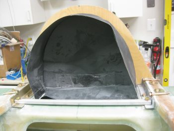
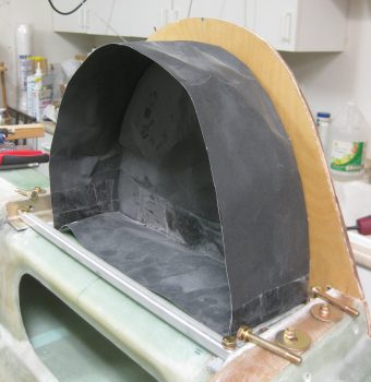
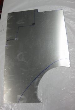
I started with the Triparagon. I had outlined the final shape on the same piece of 0.090″ 6061T6 Aluminum that I used for the brake heat shields.
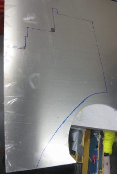
I loaded up my Skil saw with a finer tooth blade and ripped the Aluminum plate to produce the aft edge of the Triparagon.
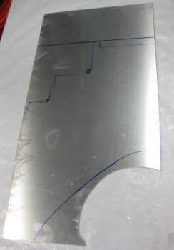
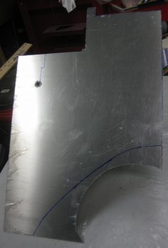
I then cut out the Triparagon top edge.
I drilled a large hole in two of the corners on the front side to create a nice radiused inside corner, then continued to use the Skil saw to cut the Triparagon to shape.
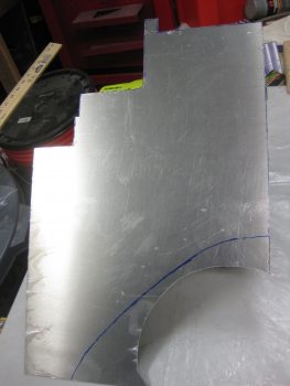
I finished all the areas I could on shaping the Triparagon that required the Skil saw. I then switched to using my Jig saw to cut the rest.
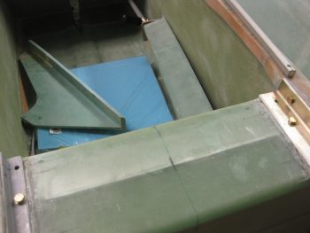
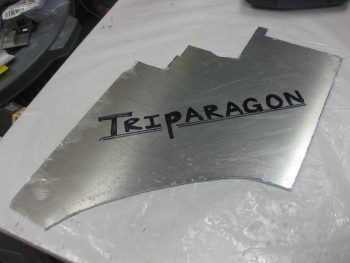
And here it is! The vertical Triparagon plate is cut to shape, and thus the first step of many is complete in the creation of the Triparagon ….
With the Triparagon cut, I then moved on to the upper engine mount extrusions. I grabbed a 1/2″ drill bit and used it to ream out the glass & foam surrounding the outboard bolt holes in the longerons.
To avoid the same issue that we have when mounting the landing gear extrusions with small washers in subsequently having them embed themselves into the comparatively soft Spruce structures, I decided to use AN970-4 washers on the outboard side of the bolts holding the engine mount extrusions to the longerons.
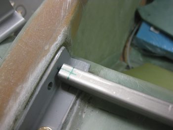
I started by marking a line the width of an AN970-4 washer over each hole right at the junction of the outboard longeron edge and the attached foam and glass. I used the Fein saw to cut a slot over each hole. I then used a 1/16″ drill bit in a cordless drill to carefully “grind” out the foam to enable me to slide an AN970-4 washer into each slot.
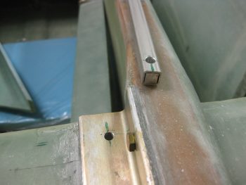
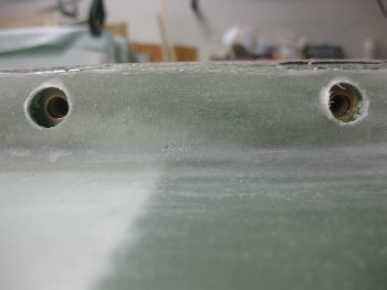
As you can see by the pic below, in standard configuration the AN970-4 washers are too tall and peek out of their slot. I expected this would most likely be the case, so I simply marked each side of the washers and used my Dremel tool to shape them.

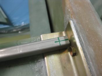
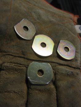
Here are the 4 outboard AN970-4 washers shaped to fit into the slots I made on the outboard sides of the longerons (… without poking out).
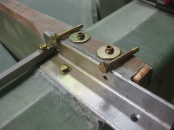
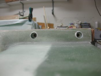
Here’s a shot of the port-side longeron with the engine mount extrusion holes. You can clearly see the modified AN970-4 washers through the outer 1/2″ holes.
After I got the washer slots made and the AN970-4 washers trimmed to fit, I then moved forward with sealing the bolt holes that I drilled through the Spruce wood hard points. Per the latest CSA and in conversations with Terrry Schubert, apparently over longer periods of time the bolts will actually start corroding due to the moisture in the wood. To remedy this, any bolts placed through wood should have the bolt holes sealed with epoxy first.
I didn’t know about this nor did I do it on the main gear bolts, so I’ll just have to remain vigilant and watch those bolts. But from here on out all bolts & screws mounted through wood will have the wood holes sealed first. As per Terry in the latest CSA newsletter (October 2016), the way to do this is to mix up some epoxy and then simply add just a bit of alcohol to the mix. Apparently this allows the mixture to flow much better and really seep into the wood. The one thing I had forgotten before I reread it tonight is that it takes multiple coats to seal the holes… so no finalizing the extrusion mounting tonight! Again, as per the CSA plans I used a Q-Tip to apply the epoxy/alcohol mix into each hole.

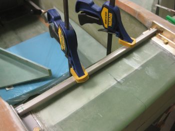
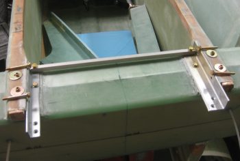
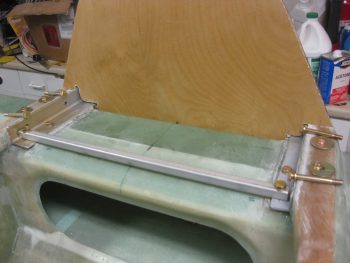
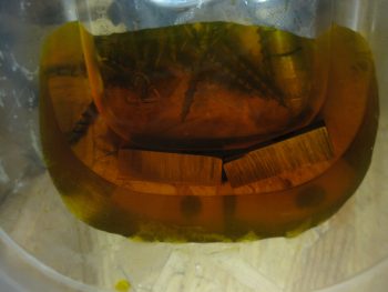
As my first round of epoxy/alcohol mixture was curing inside the wood bolt holes, I went through the process to Alodine the two 2024T3 inserts in each end of the GIB upper seatbelt bar. I first submerged the pieces in Alumaprep for about 3 minutes, giving them a good scrub about half way through. Then I rinsed them thoroughly and set them in place in the Alodine as you can see in the pic below. I let them sit in the Alodine for just over 3 minutes . . .
And then again rinsed them thoroughly with water. I then let them dry out on a paper towel, as you can see below.

Before calling it a night, I applied one more (and final) coat of the epoxy/alcohol mixture to the top engine mount extrusion bolt holes in the Spruce hard points. I’ll let this cure overnight then start tomorrow by actually bolting the upper engine mount extrusions in place.
In addition, I plan to work on the GIB upper seatbelt straps crossbar since I would like to get that checked off the list. Finally, I may cut the small top shelf cross piece for the Triparagon. I’d like to get all these tasks wrapped up so that next Monday I can start back on the wheel pants install. Allowing for my flight lessons of course! (clearly I’m not flying now due to this cold).