Chapter 22 – Finished intercom bracket

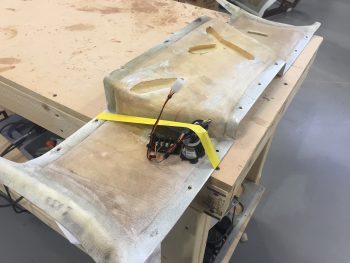
Today I finished getting the Dynon intercom installed into the intercom bracket that I just glassed to the sidewall.

I hate to admit it, but with the curve of the sidewall that I failed to take well enough into account, I had to move the forward two K1000-6 nutplates inboard just a hair to get the intercom to mount correctly.  The front nutplates were off a bit, especially in conjunction with the aft 2 nutplates.

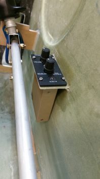
The lower body of the intercom just barely kisses the sidewall on the forward side, which is close to perfect as far as what I was looking for on the angle of the intercom.  I’ll stick a piece of double-side sticky tape foam at that corner and it will keep everything nice and tight, with a little separation between the intercom corner and sidewall.  In addition, in the pic below you can see that the stick is all the way left that it can go before the bottom of the control stick bracket hits the sidewall.  Sitting in the airplane this action would most likely be near impossible to accomplish at this severe angle of bank since the pilot’s leg would be in the way (at least mine would be!).  Regardless, my point is that even with the control stick maxed out to the left, there is still clearance between the lower control tube and the lower intercom box.

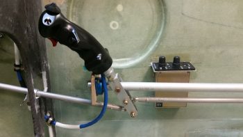
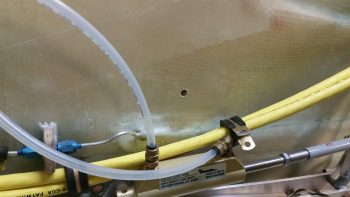
Moving on.  Later this evening I figured out my big power cable reroute which is essentially a Bell Curve looking deal that goes up & over my right rudder pedal travel path.  After having to move the rudder pedals forward, and having skooched them in a bit close to the sidewalls, I could no longer run the big power cables along side the right rudder pedal as I had planned for originally.  The fit was very tight before, but after moving the pedals forward it just simply wasn’t going to work.

Rerouting the big power cables worked out for the best anyway though, considering if I had gone with my original plan I might not have known how tight the rudder pedal and big cable clearance situation was until I tried to adjust the rudder pedals forward for a taller pilot (or if I hit another growth spurt… ha!)

Thus, the process of rerouting the big power cables is the same as eating an elephant: I’m doing it one bite at a time!  Tonight I drilled the first new hole in the nose sidewall and prepped it for inserting a Rivnut.

I then prepped the Rivnut by taping up both ends, and then floxed it into the hole.

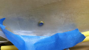
I’ll let this Rivnut cure in place, then mount the cable with an Adel clamp in the Rivnut before figuring out exactly where the next Adel clamp needs to go.  I’ll then flox in the next Adel clamp hardpoint, let it cure, and repeat the process until I get the big power cables over & around the right rudder pedal and to the instrument panel . . . at a minimum.


Chapter 22 & 25 – Done, Done & Done!

Today I got a few things checked off the list.

First, I finished constructing a micro spreader to hopefully accelerate the finishing of the aircraft surface in prep for painting when the time comes.

Here’s a shot of the actual bottom plate working surface.  You can see I used 2 counter sunk aluminum rivets per bracket to hold the bottom spreader plate to the 4 individual brackets.  I figured 2 rivets per bracket would be enough since the primary force on the spreader plate is from the top as it pushes the micro over the aircraft skin.  If there is any issue I can of course beef up the bracket attach points.

Next, I got this pic from Marco showing my finished Nose Gear AEM box and a United Airlines bear he picked up for my little 7 year old buddy (a friend’s daughter) who loves flying.

Finally, the box Marco 3D printed for me for the Nose Gear RCU had a slight blemish on the lid, so I’ll hope he’ll forgive me for me filling it in a bit and painting the lid black.  Here’s the finished Nose Gear RCU box ready for mounting into the aircraft.  I will of course have to terminate the wires on the “B” side of the connector.

With my bridge sander, micro spreader and RCU box distraction projects out of the way, I can now get back to my list of electrical system related taskers that need to get knocked out.


Chapter 25 – Finishing Tools

Today I drilled the U-channel on the Harbor Freight handle base to allow me to mount it to the bridge sander.  Before I bolted it all together though, I trimmed the inboard edges of the two cross supports at a sharp angle, and trimmed down the height of the U-channel brackets that hold the handle in place so that there would be no interference by the handle of the sander’s operation.

After all that was done, I bolted it all together and tested it out.  Looks like it will work great!

As you may be able to tell in the pics, I mounted some 32 grit peel-n-stick sandpaper to the bottom plate, and it fit just about as perfect as it can get.

Thus, the bridge sander construction is complete and this baby is operational!

I then got to work on constructing the micro spreader.  I cleaned up all the brackets by filing down the edges.  I then measured, drilled and mounted the brackets to the micro spreader base with 2 aluminum rivets at each bracket.

In this shot below you should get a decent shot of the rivets that are holding the brackets to the base.

Here’s the underside of the spreader base, with the 2 rivets per bracket visible.

It’s a bit late and I didn’t want to make any more loud noises building this thing, so I called it a night and mocked up the micro spreader to see what it will look like when I finish it tomorrow.

That’s all for now folks . . .


Chapter 22 – 3D Printing AEM Box

Not me of course!  I just got these updates from Marco.  After some trials and tribulations with his 3D printer he was finally able to get a good print on both the AEM box . . .

… and the AEM box lid.

Since I pulled the trigger on the Laserware SF11/C laser altimeter I will soon have all the components required to implement Marc Zeitlin’s new nose gear Auto Extend System, with a twist of course: the backup battery emergency gear extension feature.

To get an idea of what it will look like installed, this is Marc Z’s laser altimeter installed on the inside of his Cozy gear leg cover.  Of course the Long-EZ doesn’t have this gear leg cover, so my laser altimeter will get installed inside the hell hole near the gear.  Also, note in the pic below that Marc mounted the 12V-5V converter near the laser altimeter, whereas my converter will be located in the AEM box above.

Finally, in a discussion I had with Marco I send him this pic of my GRT Mini-X Magnetometer.  Since I had it on hand I thought I would post it here.

It’s been a bit of effort to get Marc Z’s new gear system implemented, especially with redesigning the 1.2A backup battery emergency extend circuit back into Marc’s scheme. But in the end I think all this extra effort will definitely result in a much more refined, simple, optimized and user-friendly nose gear system.