Chapter 22 – “Deslumpifier” installed

Today I started out by attaching about a half-dozen preprinted labels to component wires on the instrument panel.  By the end of the evening I had printed out another 2 batches of heat shrink wire labels and attached nearly all of them to their respective wires.  I have to say that printing out and attaching wire labels is definitely an exercise in perseverance and patience, but in the end I know it is way worth the effort.

Again, since the weather is so amazingly cold, I figured now would be a good time to get some really boring administrivia knocked out.  It’s been forever since I inventoried my spreadsheet of 2-character component electrical codes, and since I needed another 3-4 codes for some newly acquired components, I spent well over an hour checking the list, getting rid of old, unused codes, and making up new ones for the new electro-whizzies that I’ve gotten in over the past month or so.  I also printed out the codes and attached them to every electrical component without one, so all is up to date for all the electrical codes on my stuff!

Another can I had been kicking down the road was ID’ing and labeling my Inline Fuses.  It really is the nature of the beast during a build like this for so many components to change as electrical system design and configurations change.  I’ve had “IF00x” listed out for almost all my inline fuses for probably over a year now.  And since my system is much more dialed in and closer to final than a year ago, I figured now was the time to figure out the sequential numbering for all the Inline Fuses.  So I got that list knocked out and updated, then just as I did with the 2-character component codes, I printed out labels for the Inline Fuses and attached them to the appropriate inline fuse.

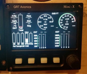
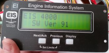
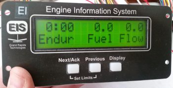
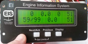
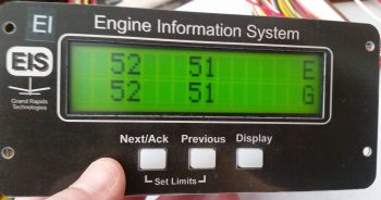
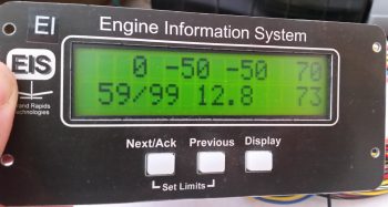
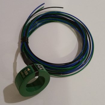
When I checked the mail today I finally received the CS-01 Hall Effect sensor that I ordered from GRT.  As I was configuring the settings on the EIS4000, I did a quick read on how to set up the CS-01.  With it in hand however, today I did some much more thorough research on just how to install the CS-01, including going back and looking at my notes.  I had a few questions, and between the GRT forum and the AEC forum I was able to find the answer…. plus a few other nice-to-know tidbits [Note the “HA” code label].

Along with tweaking the settings for the CS-01 Hall Effect Sensor, I had some other updates I needed to do on the GRT EIS4000.   So I hooked it back up, fired it up, and tweaked some limit configurations and auxiliary port settings.

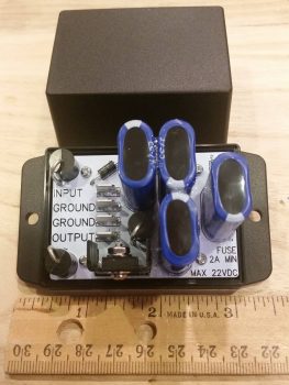
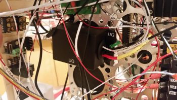
I then worked on constructing some new power and ground cables for the “Deslumpifier” AKA Voltage Slump Eliminator.  Since the power IN for the Deslumpifier needs to be fused, I just picked a location on the Triparagon that allowed me to simply use a robust inline fuse holder with leads as the main power cable.  Right now I’m fusing it with a 7.5A ATC fuse which I think is a good starting point.  To match the massive leads of the inline fuse power cable, I used a black 14AWG lead for the ground cable.

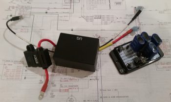
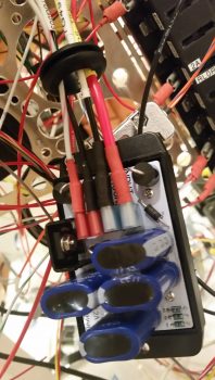
I then cut, labeled and re-terminated the existing power and ground leads to the GNS480 to allow them to be hooked up to the Deslumpifier.  After I finished the GNS480 leads, and before final hookup, I tested the Deslumpifier’s output (to ensure no power surges into the GNS480) and it showed 13.84 volts… definitely good to go.  I then terminated all power and ground leads into the Deslumpifier (note the grommet).

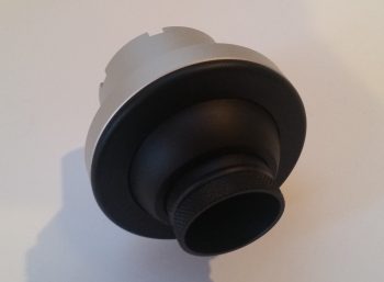
Backtracking just a bit . . . actually before I went final with hooking up the leads above, I cut an initial hole, then widened it into a slot on the end of the Deslumpifier cover where the leads connect onto the board.  After stuffing all the leads into the grommet I had a good idea just how wide the grommet hole/slot needed to be, so I then finalized cutting the appropriate sized slot for wire lead access into the Deslumpifier, including the grommet of course.  I then slid the grommet into the cover’s end slot and mounted the cover onto the Deslumpifier.

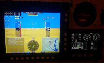
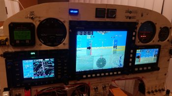
With the wiring looking good on the Deslumpifier, I then powered up the panel, including the GNS480.  Below is a wide angle view of the panel showing that the Deslumpifier works fine in powering the GNS480 in battery mode.  Much later on I’ll conduct Phase II testing which will be during actual engine start to see if the Deslumpifier will keep the GNS480 from rebooting.

I have to say that although there was a lot of mundane work that took place today, it was quite productive.  Tomorrow I’ll continue working on my instrument panel electrical system to-do list.


Chapter 22 – “Deslumpifier”

Alas, in light of the amazingly cold wx we are currently experiencing on the eastern seaboard of the United States, I’ve continued my quest to cross to-do items off my list, whether it is as banal in nature as simply ordering parts.

One such part I recently ordered was my instrument panel eyeball vent to allow me to focus heated air towards the upper part of me during cold flights.  I can tell you that right now that sounds like an especially good feature to have!  This Aveo eyeball vent was actually a bit tricky to decide which version to buy.  At first I was leaning towards anodized silver, even took a small poll.  But after getting everyones’ input and then spending a bit of time looking at both panel pics online and at my own panel, black just seemed the right way to go.  I’m sure in a week I’ll want silver again… argh!

I also received my “Deslumpifier” from electronics guru Eric Page.  He did a great job and his Voltage Slump Eliminator construction looks very professional.  It’s not too obtrusive in size and will add a great feature to my panel by allowing me to simply enter an entire flight plan into my GNS480 GPS navigator –on battery power and thus stress free regarding time (e.g. NOT sitting there burning mucho dinero in the form of 100LL)– before I then power up the engine whilst leaving the GNS480 on.  Good times!

After checking out the “Deslumpifier” I then spent well over an hour updating my engine management system and panel power electrical system diagrams, as well as creating a sheet to cleanly annotate all my current GRT EIS4000 configuration settings.

Another nice little surprise at the very beginning of 2018 was a text I received from Marco pointing out an announcement on Grand Rapid Technologies’ website.  They are now offering the special features package (EIS data display, Bluetooth and ADS-B display) for free on their Mini-X and Mini-AP EFISs.  Well, it ended up that I didn’t qualify for the “free” package, but I found out that I could get it at a greatly reduced price when I ordered my last GRT engine sensor: the Hall Affect Amp sensor.

Since I have Bluetooth and ADS-B on my HXr, I wasn’t concerned about those displaying on my Mini-X.  However, I did really want the capability to display engine data on my Mini-X in case my HXr EFIS display died inflight, so I pulled the trigger and ordered the software.

What I didn’t realize was how well laid out the Mini-X engine data display would look (IMO). A few hours after pulling the trigger on the software, I received an email from GRT and was able to update my Mini-X to display engine data.  I have to say that I’m really pleased with how it looks (of course, again, these pics don’t do it any justice!).

Here’s a wider angle view with the checklist displayed in the lower left inset on the HXr.  I did this to simply show that if I was messing about with a checklist, or had a full screen map or approach chart displayed, that with two button clicks I can very easily bring up the Mini-X engine data screen.  So, not only is it a great backup feature to the HXr, but it clearly offers a lot of flexibility to provide flight-centric information in a variety of ways.

Tomorrow should be another electrical tasker day in that I’ll most likely be doing a lot of wire & component labeling, and attempting to finish up so much of the small electrical items on my to-do list, nearly all of which are currently panel-related.


Chapter 22 – Programming EIS

The last few days has once again been ones of digging into my various engine, engine components and engine sensor manuals both for research and education on the operating limits of each item that will be tracked by the GRT EIS4000 Engine Information System.

As many of you are probably aware, GRT’s EIS Engine Information System was the first product produced by GRT back in 1991 as a result of GRT founder Greg Toman’s search for an automated engine management system for a 2-stroke ultralight engine.  Since he couldn’t find one, he simply built one!  How’s that for the spirit of homebuilt aircraft?

Barring some sideline and unexpected maintenance issues on my truck, today I was able to get both the initial and secondary (more refined) engine sensor upper and lower limits configured into the EIS unit.

Additionally, Nick Ugolini was kind enough to share his EIS4000 wiring configuration diagram with me as well, which served as an excellent qualitative crosscheck on my configuration. Moreover, my decision to mount the EIS4000 control head in the GIB headrest (i.e. “D-Deck” or “Turtleneck”) was based on Nick’s configuration that he shared on his blog (admittedly, in my ignorance at the time I didn’t think it was best to mount the unit so far aft… but it didn’t take long to realize that it was a great idea).

You might be asking how exactly this EIS control unit mounted in the GIB headrest displays engine data on the panel EFISs.  It’s actually very simple in that it relies on one 22AWG wire RS232 serial connection between the EIS4000 and the panel mounted HXr and Mini-X EFISs.

Besides just getting the unit powered up, as you can see in the pics I was able to get some “stick time” on navigating through the EIS4000’s menu pages and getting the initial settings configured.  Also, by assessing the configurations on my AUX ports I was able to play the shell game on paper and reassign 3 of the engine sensor connections with newly associated AUX ports which allowed me to avoid major re-configurations of EIS menu items.

Tomorrow I have some more digging around in the manuals for some “final” verifications on some of my upper and lower limits, such as the ECi IOX-340S’s EGT and CHT numbers.  I’ll also continue prepping for the engine build and knocking out panel wiring tasks.