Tooling Up – Yep, Mill Machine Wall

Today I finally got the back right wall finished, at least to the point where I can move forward with the rest of the walls.

As you can see I added white vinyl panels to the wall paneling to protect the wood from cutting fluid that will be flung its way during machining operations.

The blue cabinet in the bottom center of the pic is the base stand for the milling machine. I placed it there to get a better perspective of the space requirements I was looking at for installing the mill.

As for the white wall covering, I still need to add white plastic caps to cover the screws, mainly for aesthetics but to also protect the exposed screw heads.

Tomorrow I will start work on the wall 90º to the right of this one, which will also entail removing and replacing both a window and pretty much all of the workbench shown in the lower right side of the pic above.

Tooling Up – Milling Machine Wall

First off, I knocked out the final piece of the workshop compressed air system by installing a CamAir QC3 filter/dehydrator canister. This setup is connected to the shop’s compressed air system via the reel hose as it is shown connected here, and will only be used when I have a no-kidding need for really dry air as when shooting paint . . . or for any other future tools that may need super clean/dry air.

Over the last couple of days I finished framing out the back right wall to allow for cabinet installations on each side of the window. I then set about cutting the blue-green 2″ foam insulation and installing it.

As the first piece of top wall panel I reused the large 1/2″ piece of plywood that was previously attached horizontally to this wall, and then added more OSB panels around it.

Here’s the finished product…. as in insulated and paneled.

I had already assembled one of the cabinets last week. Tonight I installed it on the wall to the right of the window. I then assembled and installed the cabinet to the left of the window. As per this blog post’s title, this area –and thus the cabinets– will be for the milling machine, which will pretty much be centered on the window.

Unlike the workshop walls I previously finished, this section of wall will get an overlay of a thin white vinyl sheeting (often used in restaurant kitchens) to protect the wood panels from cutting fluid overspray that will occur during milling operations.

Chapter 26 – Seats: Phase I complete

Today I finally got a major milestone knocked out on the airplane build: Phase I of the front and back seat core fitting.

After finally spending a good amount of time –1.5+ hours to be exact– test-fitting the seat core fitting and comfort, I then annotated all my notes into an email and sent it off to the good folks at Oregon Aero. Then 2 different ~1 hour long phone calls ensued to discuss the particulars of my seat configurations and the tweaks required to modify the cores to meet my requirements.

From the last discussion I was given some homework: some measurements to take… specially to enable the Oregon Aero seat gurus to add vertical sections to both my front and back seat cores so that they follow the contour of their respective front and back seat structures.

Even more specifically, the data Oregon Aero really needed was the measurement from the bottom seat core aft edge to the angle at the top of the seat bulkhead, again both for the front and back seat.

This task for the backseat was simple and straightforward, taking only a minute or two at most.

However, there was wrinkle that popped up for the front seat core: the cut angle on the aft edge of the bottom core didn’t quite match the seat back. As you can see below, at the midpoint of the seat cushion this gap was about 3/4″. On each side it was about 0.9″.

I annotated this information on the pic below and then sent it on to Oregon Aero so they could deal with it appropriately. Clearly if I had blindly followed their instructions the measurement for where the seat cushion angle met the seat bulkhead could have easily been off over 3/4″.

When I say that Phase I for the seat cores is officially complete it’s because I drove about 45 minutes up to the FedEx facility at the New Bern airport to ship the cores back to Oregon Aero.

At over $100 to ship these cores back, believe you me I want to ensure that they are as dialed in and optimally tweaked as possible when they arrive back so that ZERO major tweaks are required when they go back for upholstery!

Tooling Up – Shop compressed air lines

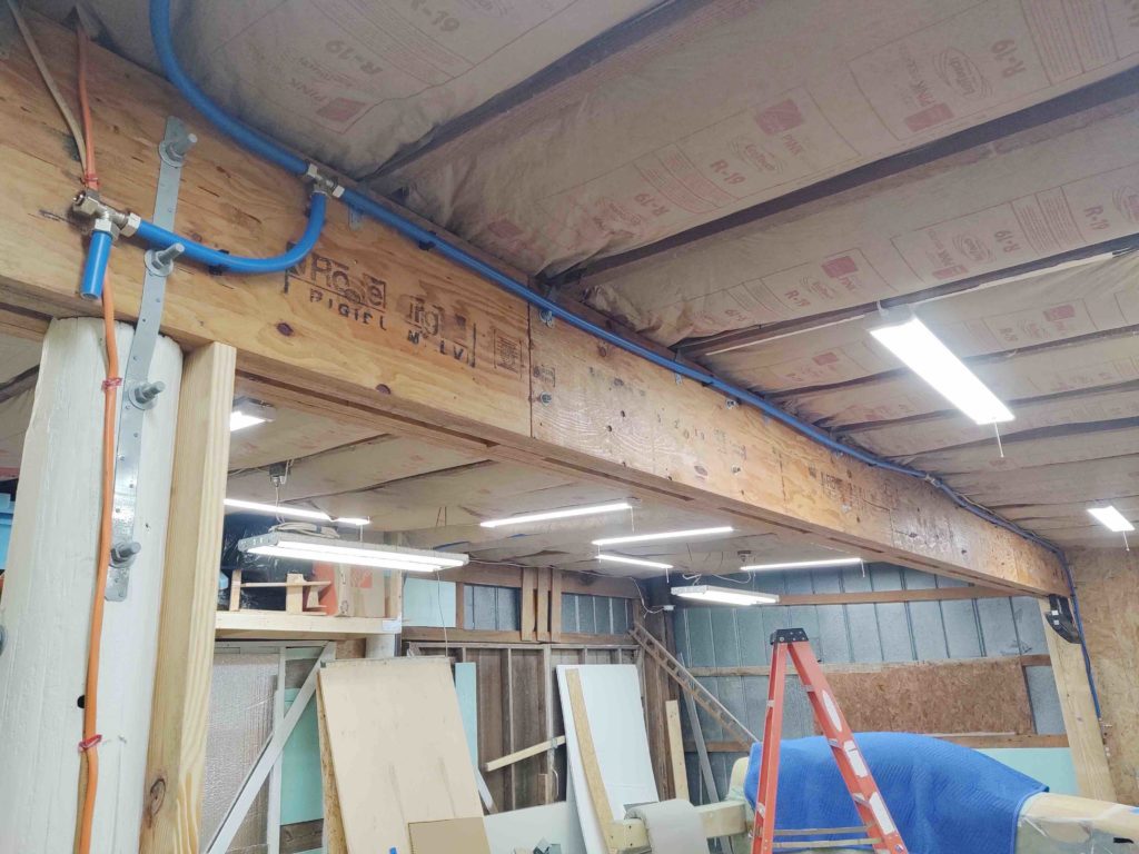
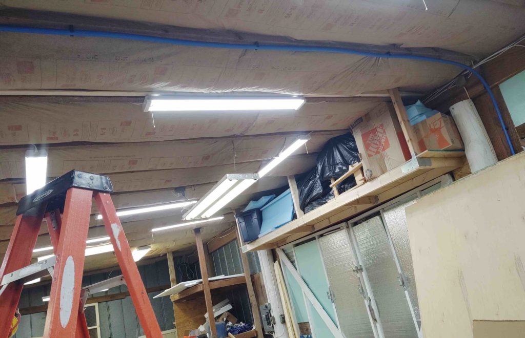
After I got the air compressor installed a couple of days ago I then started in on knocking out the installation of the workshop’s compressed air line system. I ran a line over from right next to the air compressor closet door that followed a ceiling joist over to the main beam, from which it hits an immediate “T” fitting and continues on down the length of the main beam with another “T” fitting about midpoint.

The first “T” junction on the left (upper left corner in pic below) swoops down down to feed yet another “T” junction that runs over to the right (carport) end of the shop, and also feeds the pole-mounted compressed air hose reel.

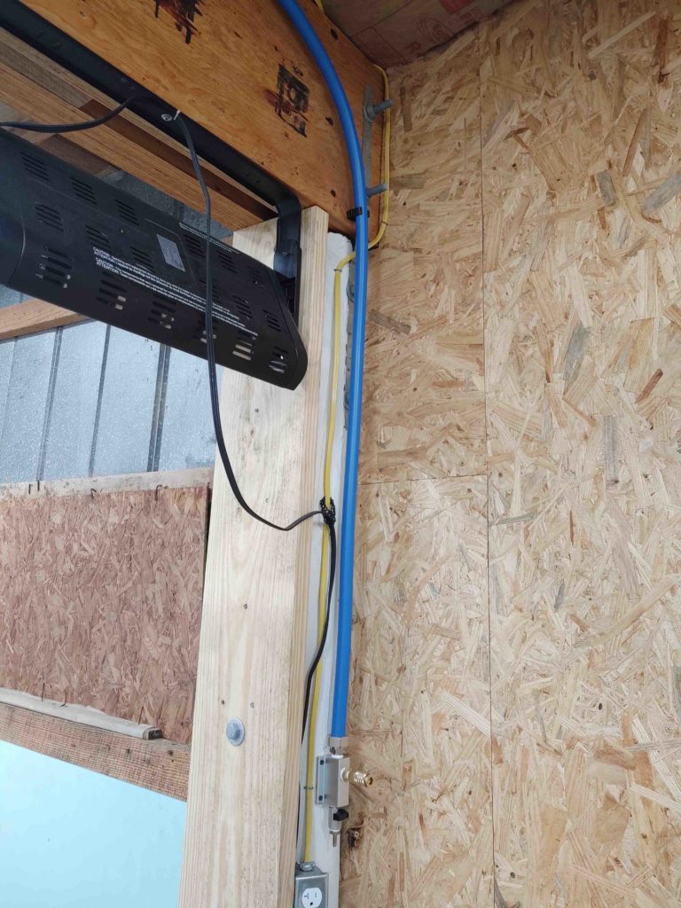
The mid-beam “T” junction carry an air line run forward to a coupler situated between the two main shop doors.

The main line then continues down to the very end of the shop to feed air to “end-of-the-line” air coupler (visible just above the plane’s nose in pic above).

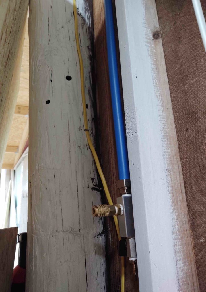
Here’s the line traveling forward from the mid-beam “T” fitting to the front wall coupler….

which we see mounted here.

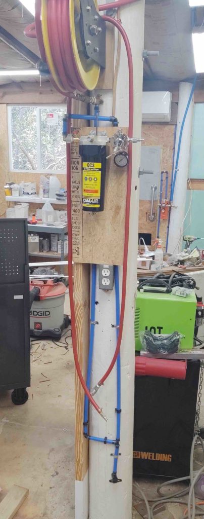
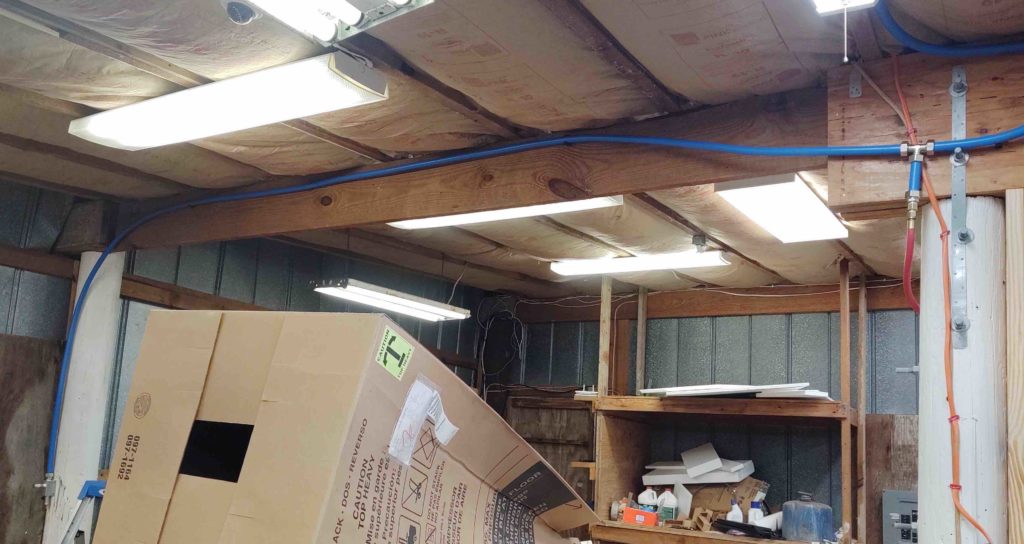
From the first set of “T” junctions (upper right) we see the line coming down from the second “T” to the red air hose reel feed and then continuing over to the left to a coupler on the side wall middle pole.

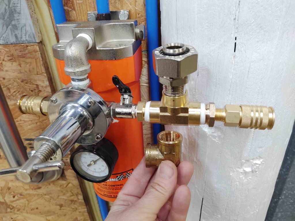
Before I could make the final connection between compressed air line system and the big orange filter I had to remedy an oversight that I had made in forgetting about a feed I’d need for the milling machine’s pneumatic tool changing drawbar.

As you can see below, I have a coupler on the left side of the big orange air filter, but that’s for miscellaneous air tools. On the right side I had previously installed the 90º elbow (which I’m holding below) for the workshop compressed air line system feed, but late last night realized I would also need a coupler hanging off the right side for a permanent line to the milling machine pneumatic drawbar. Hence, a freshly installed “T” fitting did the trick.

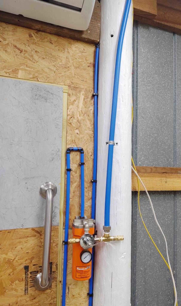
I then tied in the main shop compressed air line feed which in turn provides compressed air for the entire shop air line system.

I have one more desiccant filter to install on the center pole for an as-needed dry air feed for painting and any other future tools requiring dry air. I should have that knocked out in about an hour tomorrow.

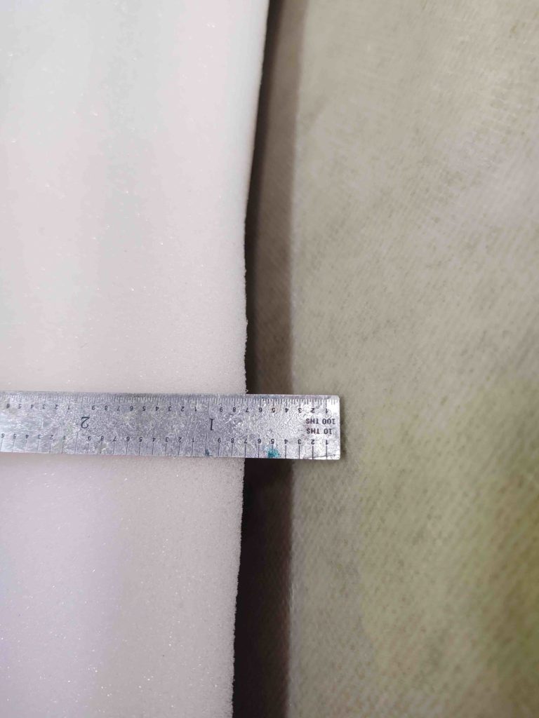
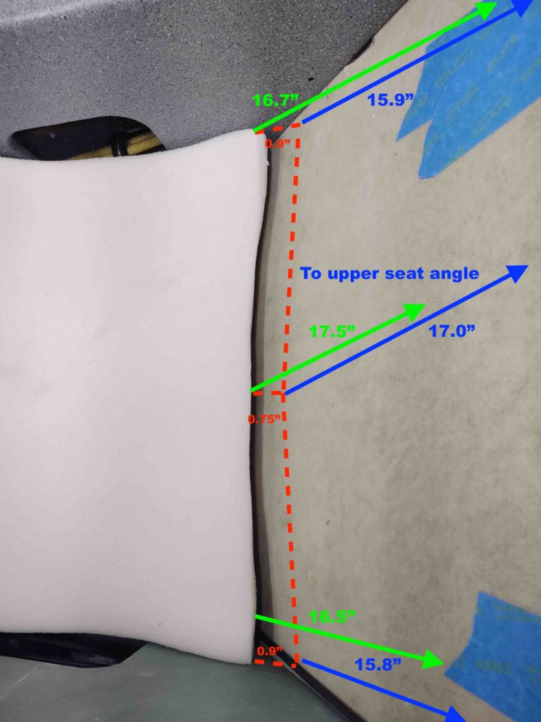
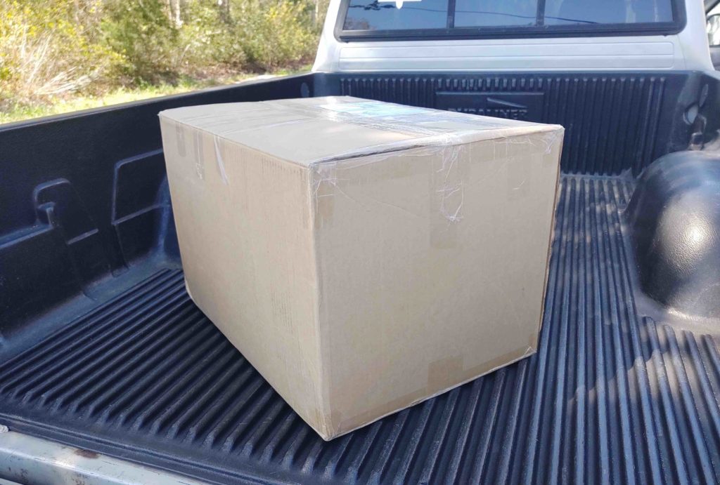
I also have the plane’s seat cores packed back up and will be shipping those back tomorrow to Oregon Aero for modifications.

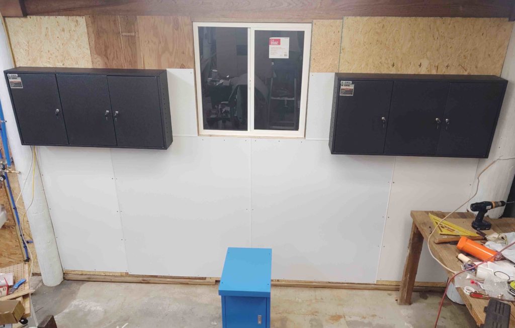
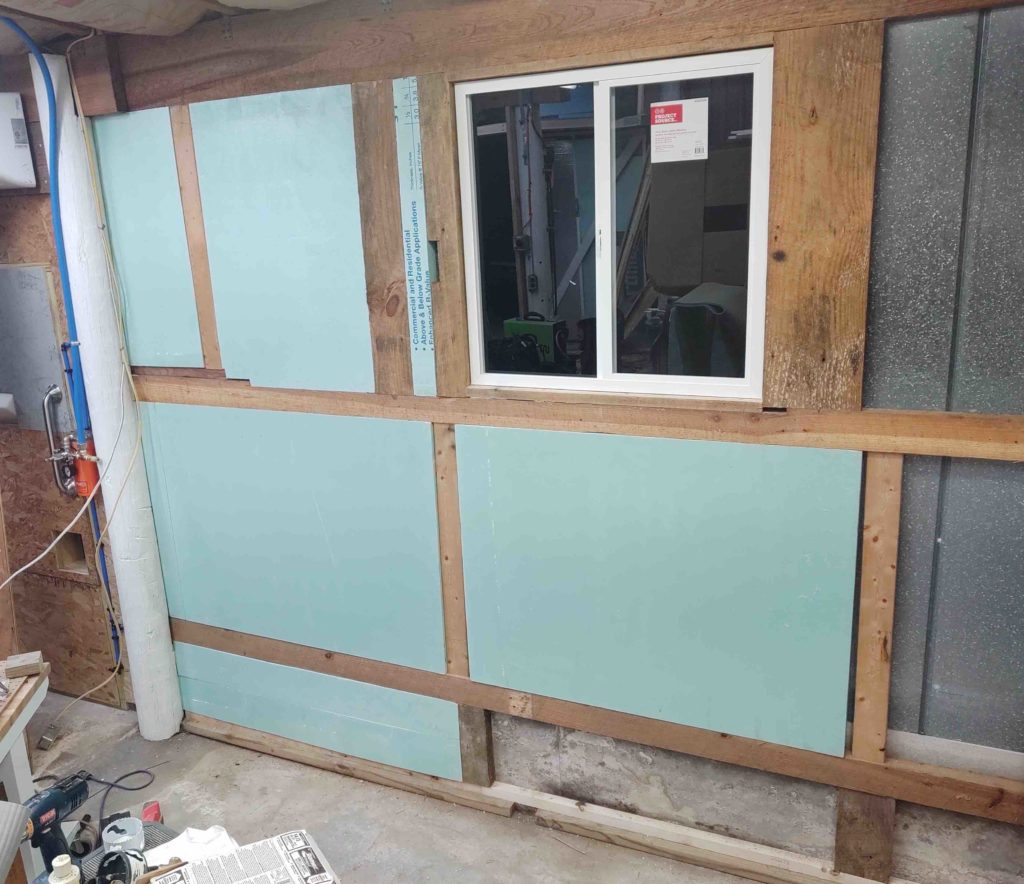
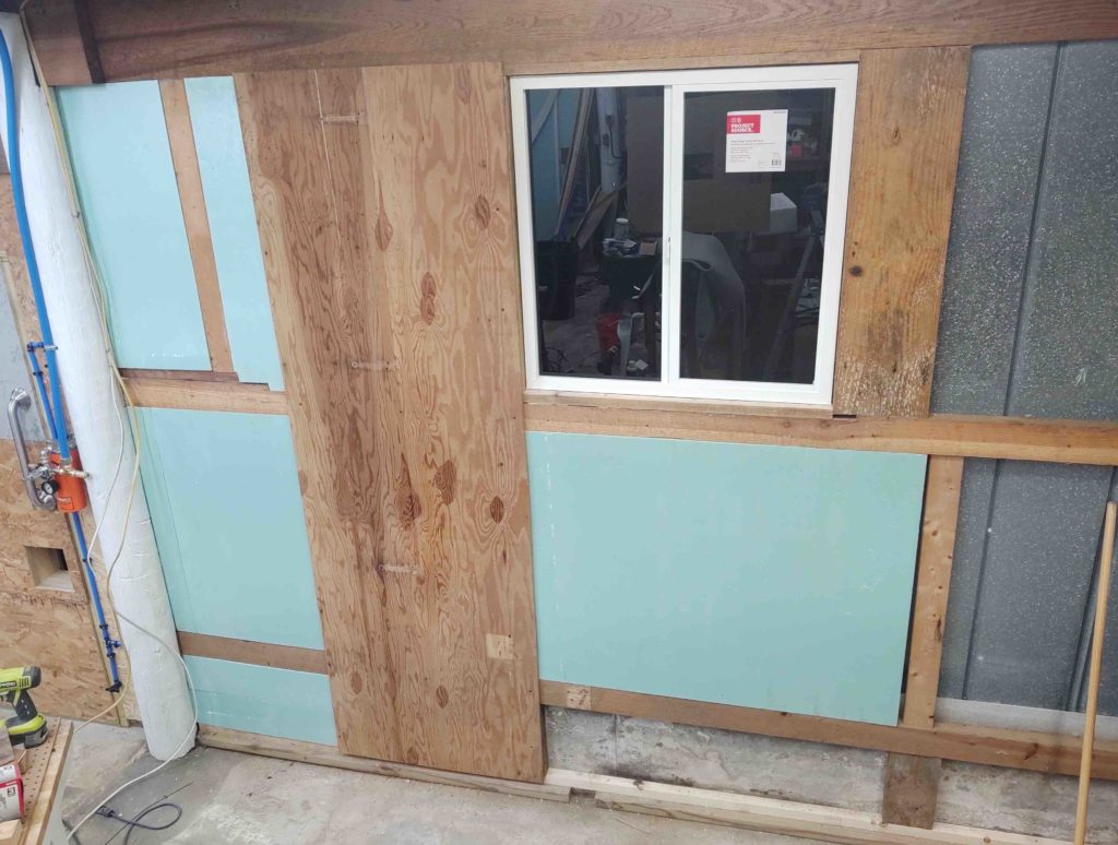
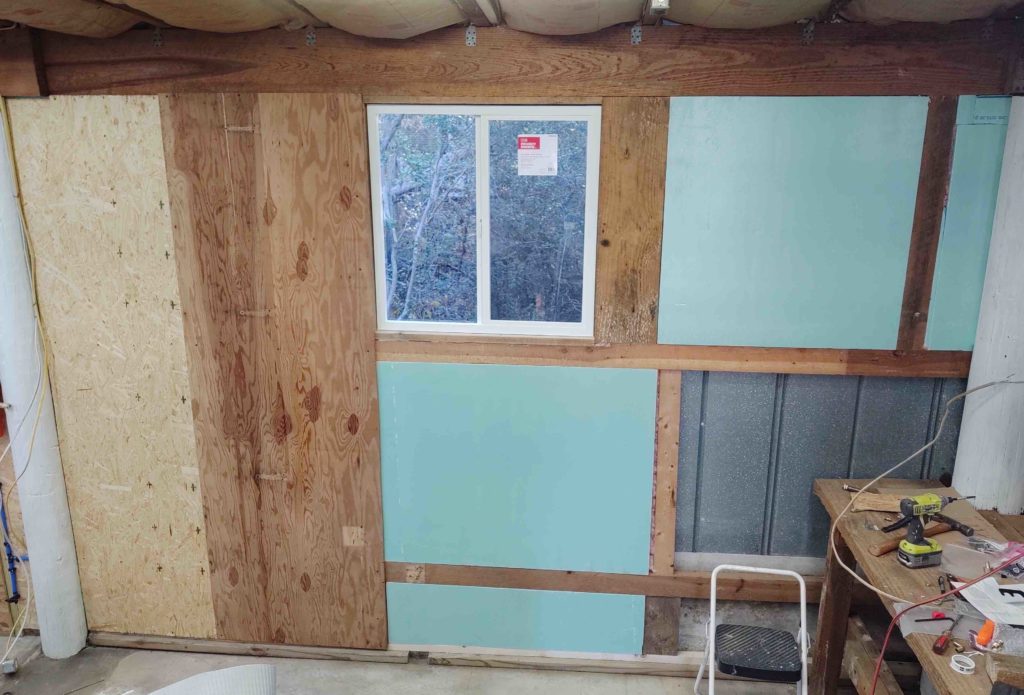
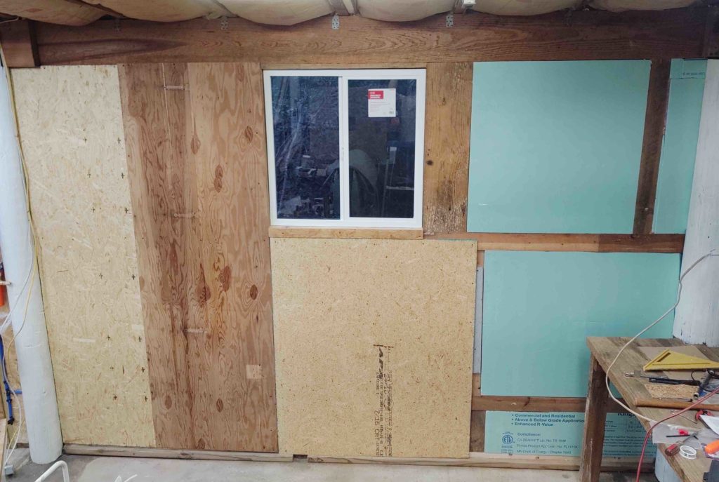
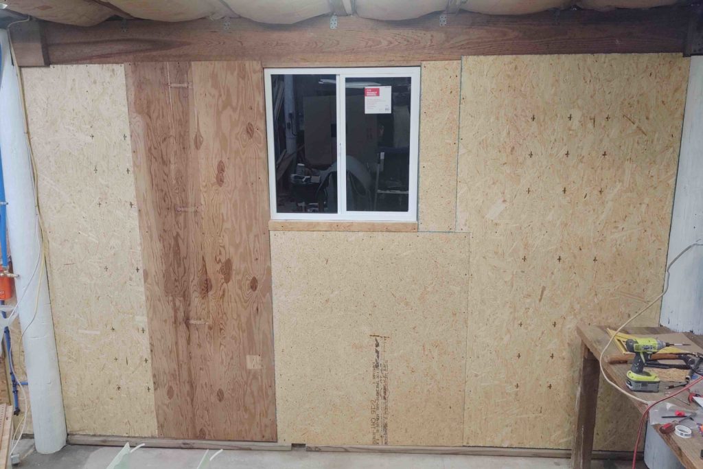
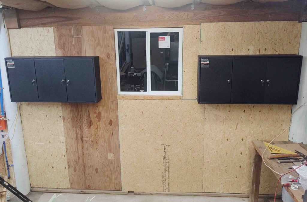
As for the workshop, you can see in many of the pics above that I have over half the walls yet to insulate and cover with OSB sheeting. I will start in on that tomorrow afternoon and hope to be finished with that in the next week or so.