Chapter 23 – Inboard ramp edges

I had a lot of external stuff going on today, so it was a light build day along with a fair bit of research.

I pulled the peel ply, razor trimmed and cleaned up the layups on the left aft inlet ramp…

. . . and the right front inlet ramp.

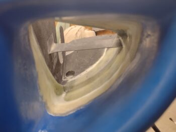
And then grabbed a shot of each through the armpit intake.

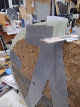
I then cleaned up the areas on the inboard undersides and sidewalls for the final single-ply BID tape layup to secure the aft left and front right ramps in place.

After cutting the glass, I then laid up and peel plied the last layup on the aft left ramp.

As well as the front right ramp.

I got an email late last night from my contact on the inner baffle molds, so if all goes right I should be getting them within the following week.

The news on the inner baffle molds along with a discussion with Dave Berenholtz on baffling, including the article “Design for optimum cooling efficiency” by Andreas Christou, triggered some thoughts I had on cooling in regards to the Mike Melvill cowling.  I thought I would include some of what I wrote to Dave here.  Feel free to respond if you have thoughts or insights on this:

“A couple of interesting things in the article is that he mentions a 140° gap on the intake side and I honestly think few canardians actually do that, although I heard it mentioned on Gary Hertzler’s Oshkosh round robin video as everybody nodded their conformational agreement.  In the same vein, does anybody go without bottom inter-cylinder baffles as he shows in his diagrams (albeit for tractor)?

Reading that document and then Klaus’ email to you gave me a bit of an A-ha! moment with these Melvill cowlings.  As I’ve been working on installing the inner air intake walls and the inlet ramps, I note that the armpit intake configuration is definitely geared at getting the air to the outer cylinder fins.  I guess one could make an argument that these are the most important overall for cooling, and I’m guessing (along with Mike Melvill’s statements & data) that these armpit inlets definitely do just that.  They do seem to keep the CHTs low and in check.

But back to the doc for a moment:  Christou states in there that; “Oil temperatures can be brought under control with good cylinder base baffles.”  I think this statement shows the weakness of the armpit intake setup and the strength of the bottom NACA cooling duct as Klaus points out.  It may also be a big reason why Melvill was having oil cooling issues and needed a bigger oil cooler because all the cooling air is flooding the outer cylinder fins with great cooling air, but the base cylinder fins are comparatively getting starved without direct air feed (although I thought it was supposed to be all about pressure vs direct air velocity… hmmm?).

I think in general terms a NACA cooling system is probably the best overall way to go, if you can dial it in to work.  I know Marco’s bird JT has a Klaus NACA duct on it and I’m sure Klaus’ is obviously as spot on NACA-wise as you can get.  A good NACA should get very acceptable cooling air to all cylinders, both at the cylinder heads and bases, and that would account for JT’s smaller oil cooler… with no issues on any of it.”

With all that being said, tomorrow I plan on getting the last ramp installed as well as beginning on the aluminum ramp vanes.


Chapter 23/24 – More inlet ramps

I started off today with the task of pulling the bottom cowling off the bird.  However, before I pulled the cowl off I spent about 20 minutes trimming and shaping the right front ramp to allow for fit inside the right armpit inlet.  I then finished removing the bottom cowling.

Over on the left side bottom cowl, I pulled the peel ply and razor trimmed the excess cured BID that secures the left armpit intake front air ramp.

After cleaning up the front air ramp, which looked better than I expected to be honest, I started working the fitting of the aft ramp.  I spent about 45 minutes trimming the aft ramp and getting it fit into place.  On Mike Melvill’s template he has a 1.5″ hole to allow air to flow through to cool the alternator (I’m assuming… there’s no label on the template for the hole or mention of its purpose in the instructions).  I used a 1″ hole saw, but drilled at an angle so I have a 1″ wide oval hole: I’d guesstimate it averages about the same area as 1.2″ round hole.

I then cut the the 2 single top plies of BID and since I’m using micro as a front edge setter & filler, I cut the aft lower edge (the curved side) ply of BID as well [I either had to use only micro on the bottom/inside front corner or glass it now, since I couldn’t peel ply the micro edge and glass later… too difficult with such little access in there. In fact, I pre- pregged this ply to facilitate laying it up].

I drilled a small hole in the inboard side wall to secure an installed nail which is what held the aft inboard edge in place.  I then mixed up epoxy and micro, put a bead of micro down along the marked front ramp edge line and after setting the ramp in place I tacked the outboard corner to the cowling surface with a dollop of hot glue.  This allowed me to do all my layups without fighting the ramp’s ever-changing position as I was on the front ramp.

After I laid up my 2 plies top and 1 ply underside BID tapes I peel plied the top side BID tapes.

Now, by moving the left side aft ramp forward about 1/2″ and lowering the ramp’s aft edge about 1/8″, the entire ramp needed to be set lower. Since I didn’t want to cut away a significant surface area of the ramp, as well as allow for the exhaust pipe that is a significant air blocking surface on the outboard edge, I went ahead and leaned this ramp inboard as I did the front ramp… even more so as can be seen in the pic below.  Remember, I can still control the final exiting of the air off the ramp with the upcoming attached top aluminum vane.

Here’s a shot of the aft ramp’s inboard edge securing nail.

After getting the aft left ramp glassed in place, I moved on to the right front ramp.  I spent about 15 minutes finalizing the trimming and shaping of the ramp so that it would fit at the position and angle I wanted, which is within a 1/2″ of Mike Melvill’s template position.

I cut 3 small BID tapes, 1 for the inside top junction with the inboard wall, and the other 2 plies for the top and bottom outboard junction with the outboard armpit scoop wall.  I had already predrilled a small hole about center of the ramp through the outboard wall (see below) and used a rivet in the hole to hold up the inboard side…. I still needed to watch the outboard edge since it wasn’t secured in place other than some thick micro fillets and the top and bottom side BID tape layups.

In fact, the aft edge kept wanting to sag about a 1/4″ so I taped the ramp trailing edge so it pulled very lightly forward and up to keep it locked into place.  I then peel plied the BID tapes.  Note that just like the aft ramp on the left side, I’ll have one more BID tape layup to do on this ramp (both inboard lower edge) before these ramp installs are actually complete.

Here we have the right forward ramp’s inboard edge securing rivet (actually one of the pins that gets removed from the floating CAMLOC receptacles).

Switching gears . . . I then unscrewed and pulled off the GIB headrest surround cover to expose the cured foam platenut tabs secured in place with micro.  Actually, before I took the cover off I threaded the screws all the way out, then all the way fully in, and then finally all the way back out to ensure that the micro’d-in foam tabs were secured… they didn’t budge at all.

I then made up 3 new #6 platenut assemblies using 1/32″ G10 plates that will then get secured into the next round of foam tabs as before using micro and a ply of BID [BTW, I forgot to mention that I weighed a completed foam platenut tab with screw at a whopping weight of 3 grams… not bad].

Again, I’ll assess whether 6 total screws on the GIB headrest surround cover will be good, or if I’ll need to add an extra pair for a total of 8 screws.  Tomorrow I suspect I’ll just get the foam tabs created with the #6 platenut assemblies glassed in place.

I of course plan on getting the last inlet ramp configured and glassed into place as well.

Pressing forward.

Chapter 23/24 – Left front ramp install

I started off today by pulling the peel ply and cleaning up the glassed foam #6 platenut tabs for the GIB headrest gap cover.  I then drilled out the glass to expose the embedded platenuts.

I spent well over the next hour aligning the screw holes drilled into the GIB headrest gap cover pieces with the platenut tabs and getting those positioned correctly in the gap between the GIB headrest and the interior D-Deck surface.

Once aligned and the interfacing surfaces sanded and prepped, I then micro’d the foam platenut tabs in place.  After about 30 minutes as the fast hardener micro started setting up, I then set the cover in place and finalized the alignment of the tabs by mounting #6 screws through the cover screw holes.  I then left the micro’d-in tabs to cure overnight.

As I mentioned before, I plan on making up another 3 tabs in the next few days for the next round of securing this cover into place.  I’ll assess after that to see if I’ll stick with 6 screws total or go with 8 to mount the cover in place.  After all the screws are in place, I’ll then apply a final ply of CF on the face of the cover to make it look spiffy and add a little strength to it (it’s fairly flimsy currently).

I then spent about 30 minutes prepping, sanding, trimming and finalizing the position of the left armpit air intake front ramp.  I tried to install it by using a bead of thick micro on the aft edge each side and laying up all the plies on each side thinking they would have enough grip to hold such a light piece in place.

My haste was not rewarded and it kept wanting to slide out of position a bit… the one thing I did right on this front ramp install was use fast hardener, because as I started trimming and positioning the AFT ramp, I simply kept ensuring the front ramp was still in good position.  After about 20-25 minutes of doing this, the epoxy got tacky enough that it held its position without my coaxing it.  I’ll have to be more patient during the install of the other ramps and use a bit of hot or 5-min glue to tack one side in place while I glass the other side . . .

Here’s a shot of the left intake front ramp glassed in place from the front side.

And the same from the aft side.  You can clearly see how much tweaking the aft ramp will need to get fitted into position.

And here’s one more shot of the left intake front ramp in place with the bottom cowling mounted back on the bird.  That slight slant with the front ramp’s inboard side down is intentional in “steering” the air around the forward cold air induction tube and directing it towards the cylinder fins.

Before I mounted the bottom cowling back in place on the plane, I re-installed the left front exhaust pipe (cylinder #3) to check any interference.  Good thing too because with the exhaust pipe in place there is virtually no clearance between it and the aft air inlet ramp.

Remember, the CF piece is just the base part of the ramp and then an angled aluminum tab, or vane, gets attached to the top aft edge of the ramp.  With the ramp in the Melvill template position, I have virtually no room for a good half of my aluminum vane when mounted to the ramp.  Due to this clearance issue with the exhaust pipe, I will be moving the ramp slightly forward and angling it just a hair down to give the future attached aluminum vane some clearance.

Thankfully, with the configuration on the right side of the engine, there is not as much congestion in regards to installing these inlet ramps as there is over on this left side.  Ducking, diving and snaking the air through this virtual obstacle course of air intake and exhaust pipes is quite the challenge and is beginning to be a bit of a PITA!  Now we know why so many homebuilders build tractor airplanes… much easier! (wimps! haha).

Chapter 23/24 – Inlet ramp install prep

I started out today still trying to knock out a few low-hanging-fruit items before pressing on to more serious stuff.

I started out by pulling the peel ply and razor trimming the 4-ply CF edge layup to add more depth to the screw hole on the left front edge of the bottom cowling.  I then re-drilled the hole and countersunk it (pic 1).  And then tested out a CS screw with Tinnerman style washer (pic 2).  All looking good here!

To better assess and determine mounting of the armpit air inlet cooling ramps, I mounted the bottom cowling back onto the bird.  I grabbed these shots of the CS screws and washers “in action.”  Besides a minor bit of sanding on the front edge of the added CF to better transition from strake to cowl, this task of adding CF to finalize the cowl CS screw installs is complete (and thanks again to Dave B. for the motivational push!).

Before I dove into the puzzle that is the air inlet ramps, I wanted to knock out another not-huge task: the creation of screw hardpoints between the GIB headrest and inside D-Deck surface to mount the cover around the GIB headrest.  One reason I wanted to work on this now is that to work on it I obviously have to climb in the back seat and face aft… well, squatting there for decent amounts of time causes my legs to go numb, so I want to break up the tasks in as small of time periods as I can.

I first made up the PVC foam hardpoints inside the gap between GIB headrest and inside D-Deck surface.  I then made #6 platenut assemblies using 1/32″ G10.

I then micro’d the platenuts into the foam before glassing them over with 1 ply of BID. I then peel plied the layups.  Here is a fast forward many hours later where I’ve done a rough razor trim, with peel ply still on, of the tabs.  I know they won’t win any beauty contests (neither will the fuel vent lines that are also being hidden!) as they look now, but I’ll clean them up before I install them.

I’ll also note that these are simply the first batch.  I plan on doing a batch of these every day or two to get them in place to secure the GIB headrest surrounding gap cover.

While the above tabs cured, I then did a deep dive on assessing how and where my armpit internal ramps needed installed.  I looked at a bunch of pics of Mike Melvill’s configuration, then accounted for my cold air induction pipes that Melvill did not have. It was getting later in the evening and I wanted to wait until tomorrow before I started glassing these things in… to do a final once over of my notes (I’m certain I’ll need to mod them later on, but looking for best optimization from the start).

Here we have the right side inlet inboard wall. I was pleased that the inboard walls didn’t hinder or hamper my installing the bottom cowl.  Also, note the ramp position markings on the wall side… one forward and one immediately aft of the cold air induction pipe.

After spending well over an hour looking at Melvill references and my own notes, and then doing a bit of research, I closed up shop and headed into the house.  I texted the one other person I know using Melvill CF cowlings with air cooling: Dave Anderson.  I was curious if he used Melvill’s templates as a guide or if he improvised, since clearly after a few years now he must have worked the kinks out.  Not surprisingly he did use Melvill’s templates but had a half-dozen round of tweaks to dial in his cooling (as did Dick Rutan using the same cowling).

With a page of notes in hand I called it a night.  Tomorrow morning I’ll be heading to a local EAA chapter meeting (a first for me in NC) and then I plan to get back onto the inlet ramp installs.

Chapter 23/24 – Clearing the queue!

I have a list of about 20 layup tasks (each task could be multiple layups) that need to be done on this bird to finish up the composite portion of the build.  Currently 20 seems to be the magic number since even when I knock out a few I always seem to find a few more layups that need to be done.

Well, today I decided to knock that list down just a bit more.

I started by re-drilling the 3/16″ hole in the bottom cowling front lip 3-ply CF layup I made to increase the depth of the cowling at this hole to add some meat to hold a CS screw… which is what I also drilled out.

I then test fitted the CS screw and its Tinnerman-style washer, and Voila!  Screw position #3 of 4 total on the cowlings thickened for a CS screw. . .

With the #3 screw position completed, I wanted to get #4 knocked out as well.  Interestingly, the thickness of the cowl in this position was even less than the other 3 spots, so I added 4 plies of CF vs just 3.   After laying up the 4 stepped plies of CF, I then peel plied the layup.

With a layup under my belt, I then spent a good half hour pulling the peel ply off the right intake inboard wall CF tape layup.  I then checked all the layups on these inboard walls and sanded down any rough spots or sharp edges that were lying in wait for unsuspecting fingers to draw blood… not on this bird!

I took a short break from the shop to call Sam at Saber Manufacturing to order a 3/8″ crush plate for my “new” white backup Hertzler Silver Bullet prop, since that is the last piece I need to allow me to mount that prop as well (I’ll note that I’ll need to make up a complete new spinner since the white SB prop would be offset —due to the prop extension bolt holes being offset— from my primary silver SB prop).

Back in the shop I took the 2 OSB forms that I used to originally create the GIB headrest arch structure and screwed those to the upright/vertical tab on one of my glassing boards. I then taped the GIB headrest & D-deck gap cover onto the forms to provide a working shelf, if you will, to glass on a small tab on the left side of the cover that will essentially create a “dogleg” in the cover to go around the engine electronics cooling fan.

After cutting the tab out of the same scrap glass that I used for the cover, I then sanded both the tab and the cover edge and cleaned them with Acetone in prep for a layup.

Here is the GIB headrest surround cover plate taped to the form and the small tab glassed in place with 2 plies of BID.

And a shot from the other side of the small tab glassed in place with 2 plies of BID to the GIB cover plate. I used a thick micro fillet in the corner to help secure the tab to the cover plate.  I then of course peel plied the layup.

I had just a small amount of epoxy left over in the cup from the above layup, so I took a good half hour to fill some indentions I had on the aft top cowl lower interface surface, primarily where the intermediate sections tied into each other.  After laying up a narrow filler ply of CF, each strip around 3/8″ wide on average, I peel plied these mini layups.

I then called it a night and went out to dinner with Jess.  Tomorrow I plan on focusing on the bottom cowling armpit inlet ramps to get those positioned and glassed into place.  I suspect I’ll spend a day or two on those, then once those are in place I’ll start working on the exhaust pipe configurations.

Chapter 23/24 – Inlet walls installed

You can probably tell that I’ve had some house and personal stuff to take care of over the last few days, thus I haven’t had full build days.  Although I have still been getting at least a few hours in the shop each day.

I started off today by razor trimming and cleaning up the outside layup securing the right inlet inboard wall in place.  Remember I didn’t use peel ply, so none of that to pull.

I then cleaned up the inside edge, sanded, Acetoned and overall prepped it for its layup.  I then laid up a 1-ply CF tape to secure the inside of the right inlet wall to the bottom cowling.  I then peel plied the layup.

As I was prepping the inboard side of the right inlet wall above for its layup, I also flipped the bottom cowling over and sanded off the old paint and micro to expose a small triangular area of CF cowl surface.

I then laid up 3 plies of CF on the bare CF over the screw hole (pic 1) just as I did on the top side to thicken the immediate area to allow countersinking the hole to install a nice flush CS screw at that point.  I then peel plied the layup (pic 2).

After my layups, I then cut out and cleaned up the GIB headrest/D-deck gap cover.

Here’s a shot of the initial fitting from both sides to get a better view of each side.  Notice on the left side (right in pic) that I cut the lower side of the cover to create a dogleg that will eliminate any obstructions for the engine electronics cooling intake fan.

It took nearly 45 minutes of minute sanding and trimming to get the cover set in place without any major gaps and so that it fit as well.  Remember, once I get it dialed in and very close, then the securing hardware (most likely 4x #6 screws) I will then do a final layer of CF on top.

Here we have a straight on shot.

And with that, I called it a night.  Tomorrow I plan on working the armpit intake ramp placement and installs, in addition to some aluminum vane cutouts.  Also, I plan to start working the exhaust pipe runs in the next day or two as well.