Chapter 22 – Front seat warmer rewire

Today was another heavy research day… I keep having new information serendipitously presented to me via FaceBook, etc. ….  then I ask a question, discussions ensue, and I find myself trying to finalize various configurations on my build (not bad, but often not my intent).  Today it was specifically regarding firewall cable pass-thrus.  Yesterday it was information that Chris Randall shared on FB about wiring up the EIS4000.  I’m grateful for the information to be certain, but these little heading changes do eat up some time.

I finally got to the actual build early this evening.  All told I spent well over 4 hours rewiring the front seat warmer system with Tefzel wire vs the automotive wire it came with. There were a few places I didn’t swap out the wiring since the amount of wire that would have been removed (relay jack jumpers) or the configuration just wasn’t worth the effort.  So, all in all I’d say I ended removing and replacing about 70% of the automotive wiring with the Tefzel.  Not bad.  And, in the process reduced the wiring harness weight by over 2 oz. Nothing to shout from the rooftops of course, but at least I didn’t ADD weight!

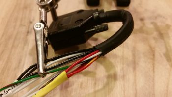
I started out by focusing on the front seat warmer switch rewiring.  I did replace the PIDG Fast-ON terminals on the switch since I wanted the higher grade Fast-ONs, plus it was just easier and faster.  Moreover, I’m getting critically low on my fine wire solder (the good stuff!).

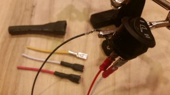
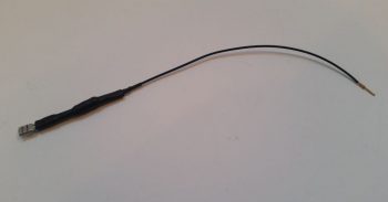
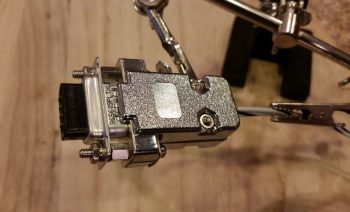
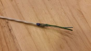
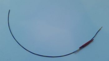
Here’s the front seat warmer switch after I rewired it with Tefzel wire and new terminals.

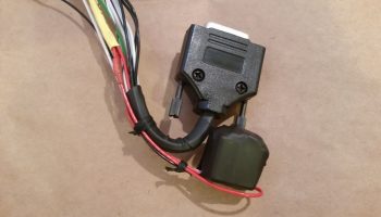
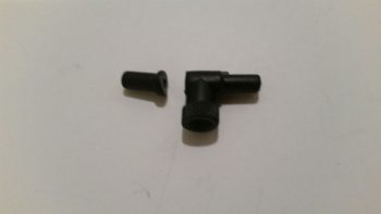
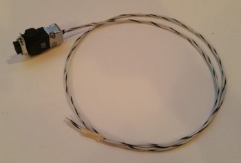
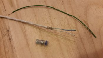
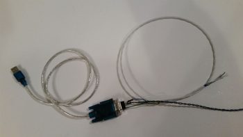
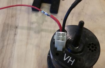
For the connector that goes on the end of the switch’s 4-wire harness, I chose to go with a 4-position Mini-Molex connector.  As I mention often, I’m not a huge fan of Molex, but this fits the bill for a lightweight, easily built connector on a non-critical component.

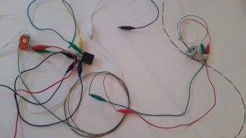
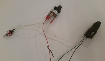
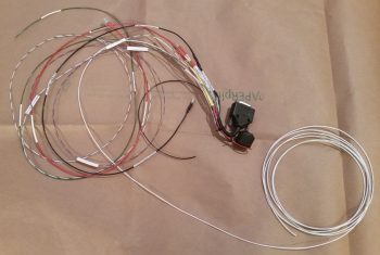
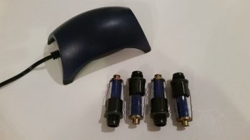
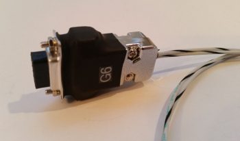
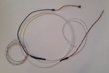
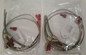
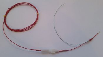
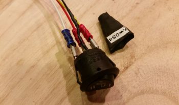
I finished the front seat warmer switch conversion, including the attachment of the Mini-Molex connector, and then I knocked out the GIB seat warmer switch conversion as well. The wire bundle on the far right is one of the original switch wiring harnesses.

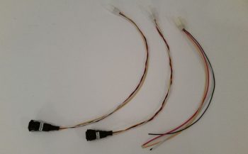
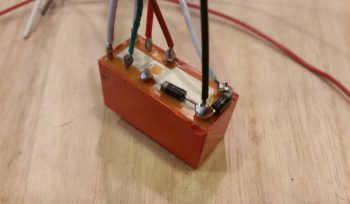
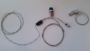
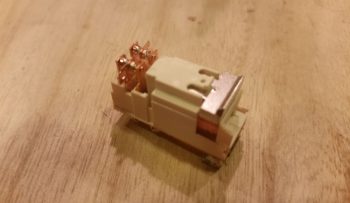
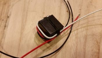
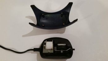
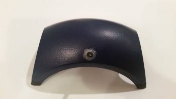
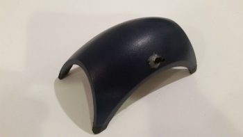
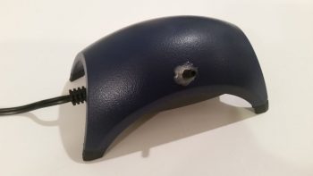
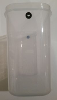
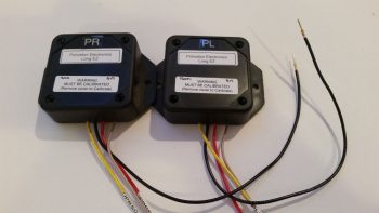
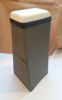
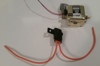
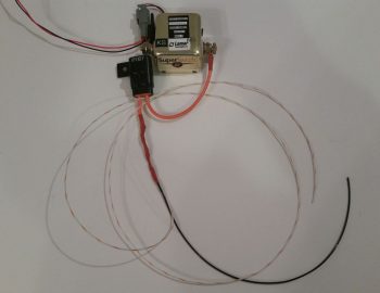
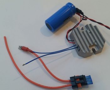
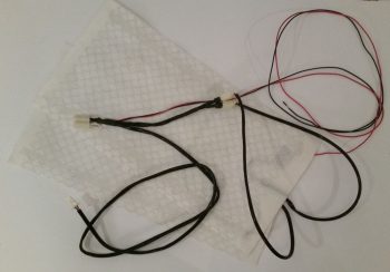
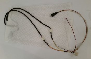
Here’s how the front seat warmer assembly looks (minus the switch harness) as it comes from the factory.

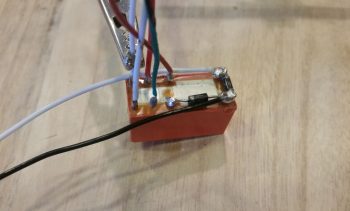
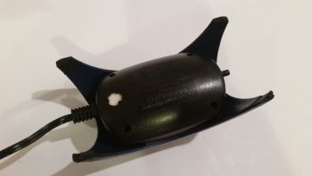
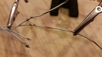
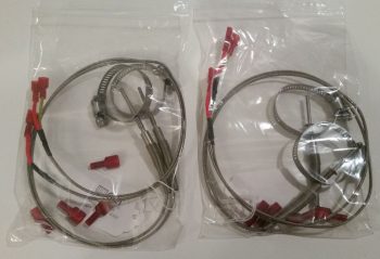
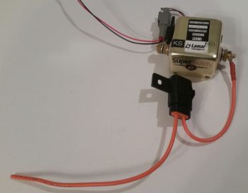
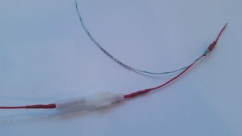
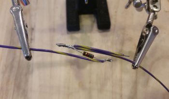
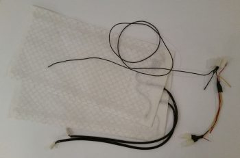
Here I’ve removed a couple of the larger unneeded sub-harnesses, and am working on the main lead wire bundles to the two separate heating pads (seat bottom and seat back).

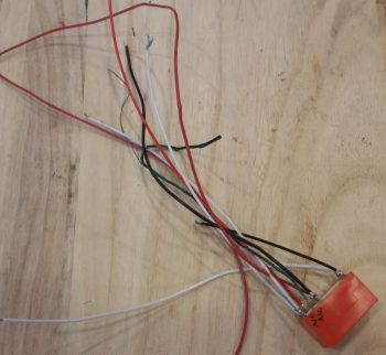
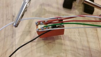
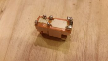
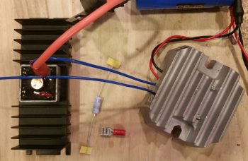
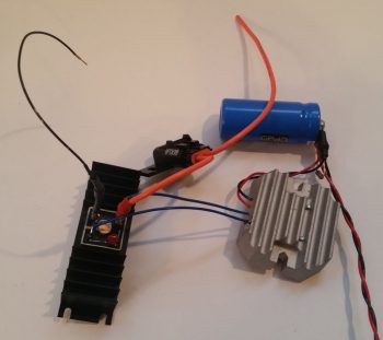
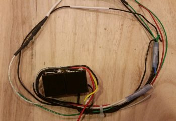
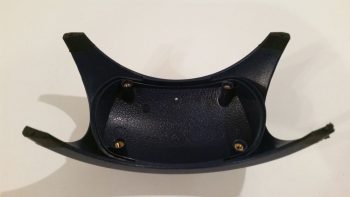
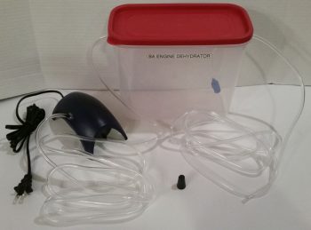
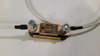
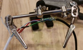
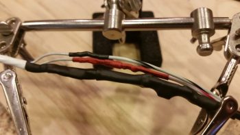
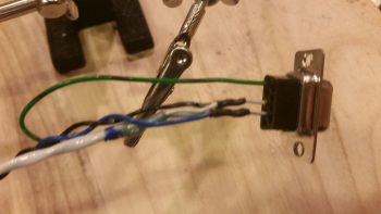
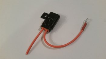
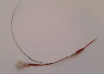
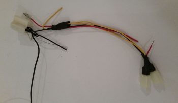
Here’s a closer shot of the main area of the wiring harness.  The white connector in the upper left corner will attach to the relay that is already mounted in the fuselage.  The two connectors in the lower right attach to the actual seat warming pads.

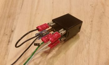
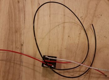
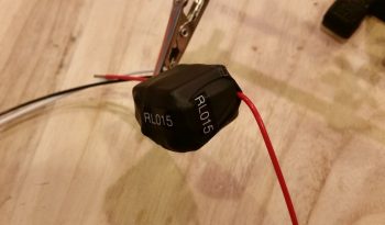
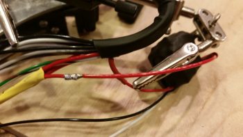
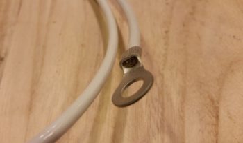
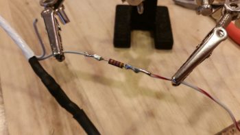
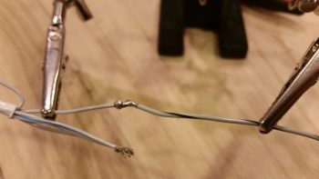
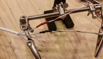
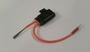
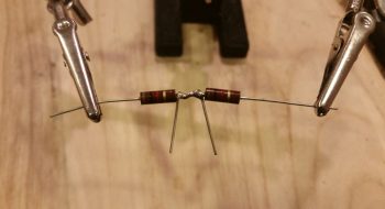
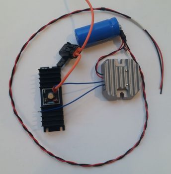
I then rewired the front seat warmer harness with Tefzel wiring.  Since the Fast-ON connectors in the relay jack have locking tabs, I figured it would just be easier to cut away nearly all the automotive wire and solder in almost completely new segments of Tefzel wire.

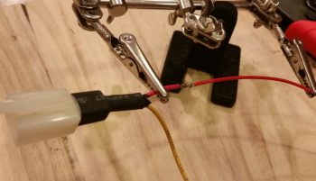
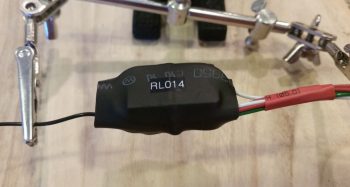
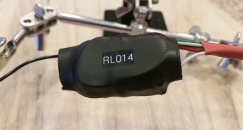
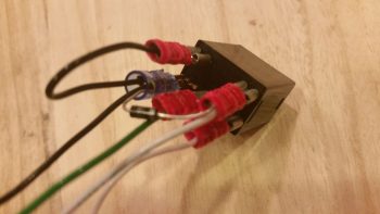
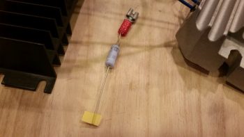
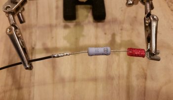
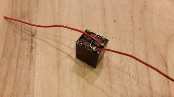
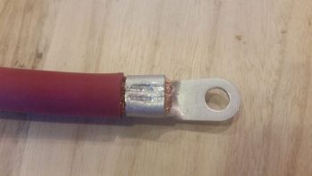
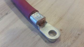
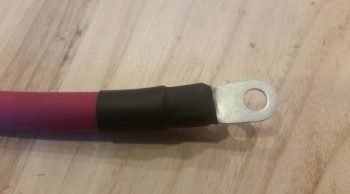
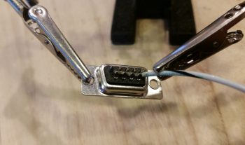
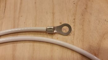
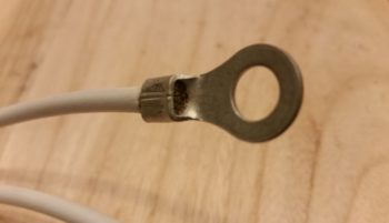
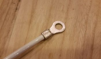
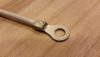
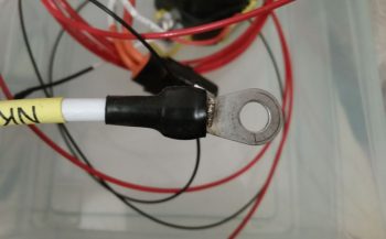
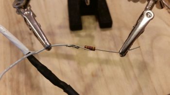
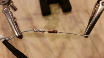
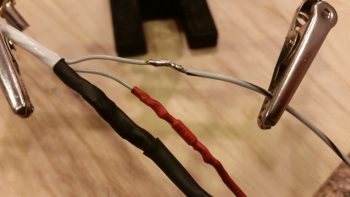
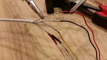
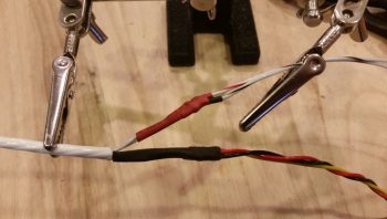
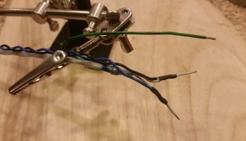
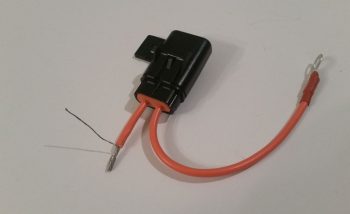
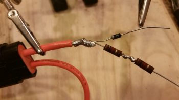
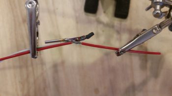
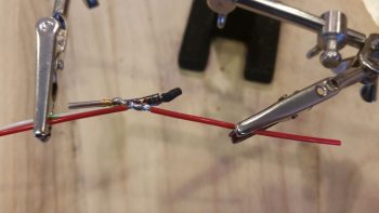
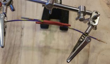
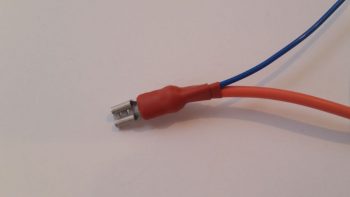
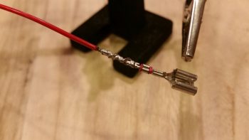
I then soldered the power wire to the Fast-ON tab.

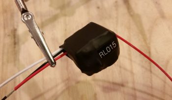
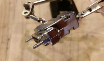
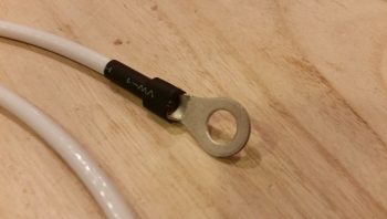
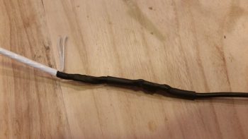
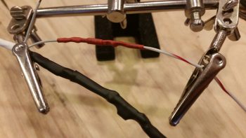
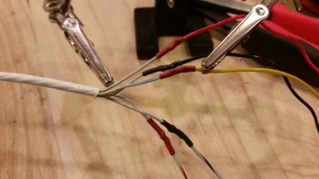
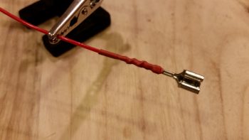
And then covered it with heat shrink.

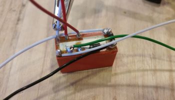
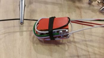
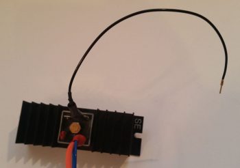
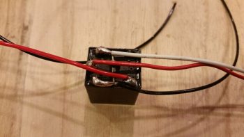
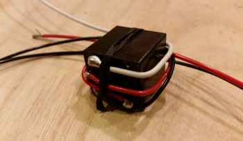
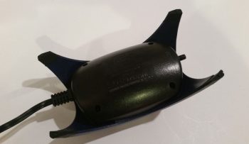
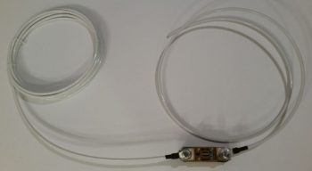
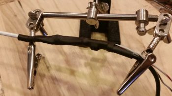
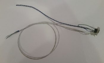
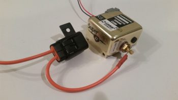
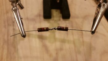
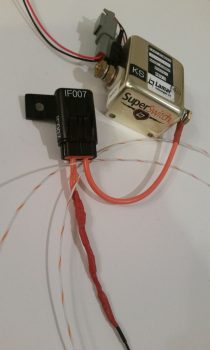
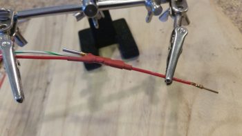
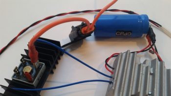
Here’s the new & improved front seat warmer setup with the majority of the wiring swapped out for the much more robust and safer Tefzel wiring.  Again, it also reduced the overall weight by a couple of ounces…. not bad.

I didn’t realize I was so low on solder until I nearly ran out this evening. I’ll order some more solder in the next day or so, but that will help facilitate my transition back into shop mode.


Chapter 22 – GIB Cabin Lights

I started out today with a goal to complete 2 things: 1) The GIB cabin map & floor lighting relay circuit wiring and 2) the front seat warmer rewiring to replace all the auto-grade wiring with Tefzel wiring.  Well, as things go on this build, I was only able to complete goal #1… but complete it I did (with a video even!) so that’s something.

I started out by reviewing the wiring circuit for the GIB cabin map & floor lighting relay, which is relay #14.  After re-familiarizing myself with how it all goes, I got some wires and diodes and got busy.

Here’s how it looked when I started.

I then added a couple of diodes, one as the flyback diode across the coils and the other for the ground lead to common.

As I was looking for a fairly lengthy ground wire I ran across a twisted pair of 22 AWG white and black wires about 5 ft long that I had picked up from Stein at some point. Knowing that I was running low on opportunities to use this kind of pre-configured stuff I quickly pressed it into service.

A point of note, however, only the black ground wire below is from the twisted pair.  The white wire is about 9″ long and goes to the white light/red light selector switch.

I then added in the green and white control wires that are used to power either the white or red LED lights on the map light (an either/or setup).

I then finished soldering all the other wires onto the relay tabs.

I then wrapped the wires around the relay and tied them with cable lace to ensure the wires were secured in place.

I then covered all that with a 1″ diameter piece of heat shrink, and finished off the relay build with a couple of labels.  Here’s side A and side B.

And here’s the whole GIB cabin map & floor lighting relay circuit wiring with the map light added into the pic. Since the floor lights are already mounted into the fuselage I couldn’t/ didn’t add them here.

Then I ran into an issue…. took me a while and some in-depth step-by-step troubleshooting to first ascertain that I hadn’t wired anything incorrectly, then next re-evaltuate my circuit to ensure I actually designed it correctly, then finally I was specifically able to narrow down my issue to the relay coil.  It was just spotty and unreliable…. for unknown reasons (to me anyway) it would work here, but not there.

I then slightly modified the circuit and used a SPDT automotive relay that I had on hand and it worked a treat (for you Dave!) . . . so I yanked the “old” relay, finalized the new circuit design, did a final test, and then wired up the new relay.

Here’s a couple shots of the new 12V SPDT automotive relay that I swapped out the “old” DPDT relay with (I’m running low on solder and honestly didn’t want to take the time, so I used PIDG Fast-ON terminals):

After I finished wiring up the new relay, I tested out the circuit.  It looked good so I figured I would try out my Christmas present from Marco: a tripod for taking NON-bouncy videos (the wimp said my videos were making him seasick…. man up! ha!).  So here it is:

With another fairly thorough test completed during the video taping, I then cut another piece of 1″ diameter heat shrink, wrapped the relay wire leads to secure them, then heat shrank it all.  Of course I then re-labled my new relay #14.

I snapped the cover off the “old” relay to see if I could see any damage or scorch marks in case I had fried it somehow (I did fry a diode about 6 months back, but the relay seemed fine…. I guess not).

In addition to getting the GIB cabin map & floor lighting relay wired up, I also spoke with Bill at Airflow Systems to see about the possibility of swapping out my 2008X 17-row oil cooler for a 2006X 13-row oil cooler.  Since I’m not using tapered cylinders on my IOX-340S engine now and my compression is not super high (9.3:1) then I’m going to make my life easier (we discussed the specs and oil cooling requirements of course) when it comes to oil cooler placement and installation by picking up an oil cooler that’s about 1.5″ less in length than I have currently.  Thus, I plan on sending my 2008X in for replacement here within the next week.

As for build tasks, the weather is getting warmer . . . during the day.  But for the next 7-10 days we still have dips down into the 30s at night.  I do plan on getting into the shop, but I will get some more of these electrical system tasks knocked out during the next couple weeks as well.


I’m here . . . still kicking!

As I mentioned in my update post, since I’ve been back I’ve been swamped with a number of “maintenance” type tasks both on the build and in my personal life.

Starting out, normally when I head south for a few days I take an hour or so each night and update my website by parsing out all my blog posts into the respective build log chapters. Well, as you may have noticed, with all the cold weather we’ve been having here I have been focusing mainly on the electrical system.  Ok, so when I tried to get into my electrical system web page it came back with a fatal error since the size allocation for the page wasn’t enough to edit it!  In addition, WordPress had just come out with another version update and I wanted a good site backup before I did the WordPress update.  In short, it was just too much of a hassle for me to mess around with while I was gone.

When I got back I researched what I needed to do to update the page size allocation limit. I logged into the server, did a site backup and then proceeded to hack into some root directory files to allow me to up the page size allocation limit.  Once that was done, I could then finally get into my Chapter 22 – Electrical System page to edit it.  My edit actually consisted of taking a good amount of the content and parsing it out to other pages, some already existing, and a number that I just created.  Once I did that, I then proceeded to do my normal updates.  To be certain, all this together was no small feat (since I had been remiss in doing any updates in the past 2 months) and all told it took over 12 hours, over a couple days to knock out.  Yes, it’s not specific airplane building stuff, but it should be the last major reorg of my site before this plane is flying.

In addition, since I’ve been back, I also updated my GRT Mini-X’s software and downloaded all the new Seattle Avionics chart and approach plate data.  Plus, I updated a few checklists on the HXr.

As you can see, it’s been a very data-centric past few days.  But with all that behind me, I updated my task/to-do list and I’m ready to get to it.

BTW, I spoke with my engine guy and I we should be figuring out when to finish this darn thing in next week or two.

Finally, the weather should be getting warmer here in the next week, so I will start slowly getting back into shop mode.  There are some electrical tasks I want to finish up, but I’ll probably work those for a few days and then start multitasking between those and shop tasks.


Chapter 22 – Antenna terminal standoffs

I’ve been taking a break over the past week to deliver another load of household goods down to my storage unit down in North Carolina in support of my upcoming move there later this year.  On the way back home to northern Virginia I stopped by to spend a couple of days with my very good friend & fellow Long-EZ builder Marco and his lovely wife Gina.

During my visit Marco very graciously opened up shop to help me in lathing 4 aluminum standoffs for 2 of the 3 GNS480 GPS antenna connectors (2 standoffs per each antenna connector).  After talking to the guys at Stein Air a few months ago, I took their advice and ordered some 1/2″ high 4-40 threaded hex standoffs from McMaster-Carr but then for some inexplicable reason forgot them at home during this trip.  Since I had one of the original hex standoffs with me, Marco and I were able to figure out the configuration and use a simple aluminum rod to lathe the 4 antenna standoffs out of it.

It took a bit to get the configuration dialed in, but once we did, Marco worked his magic and had 4 standoffs knocked out in fairly short order.

Here’s another shot of the original hex GNS480 antenna standoff and the 4 new aluminum standoffs.

Tomorrow I’ll be back home and will get back to work for a few days on electrical system. Then with the forecasted weather for the next few weeks, I plan on firing up the heaters and being back to work in the shop this upcoming Sunday.


Chapter 22 – Electron nation!

Today I received my latest order from Mouser, which included my 3K Ohm 3 watt resistor required for the SD-8 Bridge Rectifier ground lead.  With my almost last component for the SD-8 on hand (now I need to order a DPDT relay . . . more on that below), I got to work installing it.

The first task was to simply crimp a red PIDG Fast-ON terminal to the end of the resistor.

I then soldered my 20 AWG ground wire to the remaining resistor leg.

And then covered all that with some heat shrink.  And then terminated the other end with a D-Sub pin to enable connection to the new D-Deck G6 ground bus.

I then connected my latest wiring “feat” to the appropriate tab on the Bridge Rectifier.

Here’s another shot of the completed SD-8 Bridge Rectifier ground wire (this allows for self excitation of the SD-8 system . . . meaning that it can turn on without having to see voltage from the battery.  And not anything else. . .  sheesh!).

Over the past few days I’ve been pondering the solution to my IBBS charge lead disconnect during SD-8 only operations, and I finally came to a decision: I will bite the bullet and acquire a DPDT relay to replace the current SD-8’s S704-1 SPDT relay.  I then will use the extra position on the new DPDT relay to drive activating current to a small relay in the nose to then disconnect the IBBS charging circuit automatically (as in unseen by me & no additional action required by me).  This control relay activation will of course happen any time the SD-8 is turned on.

Now, I had ordered some 4-pin SPST relays for another project I’m working on and planned on using one of them possibly for this configuration, but I apparently ordered them in haste and jacked up the actual type: they turned out to be NO relays so I had to find another source.  I then dug through my scrap box and ran across the old wiring harness from Jack Wilhelmson’s EZNoseLift nose gear that was on there before I modified the system with Marc Zeitlin’s new AEX system.

I isolated the best looking relay on the old nose gear wiring harness and then trimmed all the excess wires off the top of it.  I then quickly tested out my circuit, and the relay, by hooking up a red LED and 9V battery to the NC side of the relay.  Then with the LED in a steady state on, I activated the relay with yet another 9V battery and it opened the switch, thus opening the circuit and turning off the LED.  With both my proposed circuit and the relay testing out good, I then proceeded to solder my planned wires to the relay.

I resoldered all new wires to the relay except for one (which was a red power wire… a point of note: I forgot about my service loop to keep the stress off the solder joint so I should have gone with a longer wire and not left the shorter one in place).

Here’s a shot of the relay with all the wires soldered in place, ready to go…

I then wire lace tied the wires to the relay body.

And then added a couple of pieces of larger heat shrink to secure the wires in place to the relay body.

I then grabbed the wiring harness for the IBBS.  I found and then isolated the red wire with yellow stripe that is the IBBS recharging wire.

I then cut the IBBS recharging wire lead and soldered in the red power leads from the control relay that I just wired up.  After soldering the respective wires to each other, I then hit the pre-added heat shrink with the heat gun to cover the solder splices.

I then wire laced the wires in a couple spots to help secure the new added relay.  I did want the relay as close in as I could get it to the IBBS connector, but I would have preferred even a half inch more wiggle room than I got by keeping that original short wire on the relay … but I think all should fit fine once the IBBS is installed.

Here’s a closer shot of the new IBBS charging circuit control relay (RL015).  You can also better see the wire laced spots in this pic that help to secure the new relay.

One final point of note.  Over the past week I have been slowly, bit-by-bit, converting the master Z-13/8 electrical system diagram over to my new isolated starter and B lead circuit architecture, which includes of course having the starter contactor and ANL 40A fuse link up in the nose.  Well, after a good hour tonight I was finally able to get my master system architecture updated.  With that, I truly hope that I have no major changes left to do on this system!

As a reminder, I’ll be heading to NC tomorrow and will be out of pocket for about a week. Hopefully the weather will get warmer by the time I return so I can actually get some shop work done.


Chapter 22/23 – Engine Dehydrator

I have to say that sometimes when I go to write the day’s blog post, the pictures I upload don’t really capture the story of how busy I was for the day, and today is one of those days.

I started off today by grabbing the length of 2 gauge welding cable I have that will make up the primary feed from the battery to the battery contactor.  IIRC I went with 2 AWG cable because in trying to locate a source of supply, the 2 gauge was significantly cheaper than the any other size in that general range (at the time at least) so pulled the trigger on it.  I wanted at least no less than 4 AWG, and when I ran across this piece I snagged it. Moreover, since I’m using the lighter weight copper-clad aluminum for the big starter cable run & ground return, it’s slightly thicker than normal 4 AWG wire and uses 2 gauge terminals, which I then in turn used some of these same extra terminals for this length of 2 AWG wire.

I stripped the end of the battery cable insulation back about 5/8″.  I should note that getting the terminal over the myriad of fine wires of the welding cable proved not only challenging, but did require some judicious paring down of some the perimeter wires to allow me get the terminal slid onto the exposed wire.  I had thought about possibly needing a wedge or two of copper to drive into the mass of wires from the exposed end (a Bob Nuckolls trick) to better secure this terminal (the same principle of securing a hammer/mallet/axe head to a wooden handle) but the effort to get this thing on was so intense, and the mass of wires so tight to begin with, there was definitely no need –or room!– for any wedges.

I then took the battery cable with attached terminal down to the garage, and once again used my Molex “crush-it” crimper in the vice to crimp the terminal in place . . . whew, was that quite a workout!  Since the base ring is so wide on this terminal, I set it in the crimper jaws again closer to the insulation and this time tried my hand at simply whacking it a couple times with my 2.5 pound mallet.  Worked a treat and the double crimp seems a bit more uniform along the entire side of the terminal base ring.

Here’s another shot of the crimped terminal on my battery cable.

I then went on the search for some suitable diameter heat shrink.  Here, simply because the cable is red, I made an attempt to use red heat shrink as well, but alas, I only had black in a big enough diameter to cover this terminal end.

I only did the battery contactor end of the battery cable because the battery side will have to be done at final install of all the electrical components in the battery compartment, when I know for sure how all the cables will fit, commingle and get run.

From there I moved on to prepping for the eventual engine storage in my shop.  As an aside, I did speak with my engine builder and when he gets an opening in the schedule we’ll finish the engine build.  I don’t really mind since I still haven’t cleaned out the space required in my shop, and I’ve been gearing up for taking down another load of stuff to NC in preparation for my eventual move down there later this year.  In fact, I’ll be heading down there for about week in just a few days.  So if the engine stays up at AERO Engine’s climate controlled assembly shop I have no issues with letting it sit there for another week while I galavant off to NC.  I will add to that this is exactly why I started the whole coordination for the engine build back in October of last year because I wanted to allow for the inherent fits & starts we’d have to get the darn thing completed.

With the engine being a brand new build, it is more susceptible to internal corrosion than a broken in/mid-time engine and requires some prophylactic measures to ensure it remains corrosion and gall free…. as Bill Allen points out in his video on his engine dehumidifier that I included in my last post.  Bellow are pictured the 2 primary methods I will employ to help guard against any internal moisture within the engine: A) an active airflow engine dehumidifier (dehydrator) using a small aquarium air pump at the heart of the system, and B) passive cylinder dehydrator plugs that are mounted in the spark plug holes … just one per cylinder.

For the engine dehydrator system, a couple slight modifications are required. So I removed the 4 small screws to pop the top cover off.

And then drilled a small hole at the center point, near the side edge of the cover.

There was a “T” fitting included with the pump, and since it was the correct diameter for the tubing I would be using, I cut one side of it off to press into service as an air hose barb to turn the small hole I drilled above into an air intake hole.

I then used the small drill bit that I used to drill the hole to align the inlet barb with the hole. I then used some 5-min glue to secure the barb to the side of the air pump cover.

Voila!  I now have an air intake barb on the side of my air pump.  This will allow the pump to drive air out of the standard outlet that is configured on this pump, and now simultaneously draw air back into the pump through this air intake.  This turns a standard OUT-only pump which uses outside air for a fish tank to be transformed into a closed air pump system.

This shot is to show the daylight that can be seen from the inside with the air inlet barb glued in place on the external surface of the air pump top cover.

I then reattached the air pump’s top cover and secured it with the 4 screws.

The second and final step required for this modification to transform this pump into a closed system is to tape off the filtered air inlet valve on the bottom of the pump (which somewhat resembles a small upturned decapitated rodent in this pic…)

With the application of just a small piece of electrical tape, my out-only air pump has now been transformed into a closed-loop air pump/vacuum (albeit the “vacuum” force created is exceedingly small… this is simply more just an air return inlet).

On the engine dehydrator system’s desiccant container I then drilled a 3/8″ hole at the top on each side for the tubing to be run through.  I then placed a rubber grommet into each hole.

Here’s an end shot of the rubber-grommeted holes on the sides of the engine dehydrator’s desiccant container.

And here’s a shot of the entire engine dehydrator system as it looks so far.  I have humidity meters on order and will place an order in the next day or so for the desiccant so that it will be delivered just as I get back from my sojourn down to NC.  I would like to especially thank Bill Allen and “Drummer” Dan for providing the specific details via FaceBook on how to construct this engine dehydrator.

I have a few small electrical system tasks that I will continue to work on, but those will dwindle quickly since over the next few days I’ll be gearing up to head down to NC again (as I’ve mentioned a number of times).  If possible, I’ll stop by on my way home to visit my buddy Marco to see what he’s up to!


Chapter 22 – Doin’ the LIST!

I started out today working on my D-Deck/Turtleback located G6 ground bus that consists of a 9-pin D-Sub connector soldered to two (2x) 18 AWG wires which will in turn be connected to the G3 ground bus in the Hell Hole.

I stripped off a bit more insulator than normal on the 18 AWG wires since I wanted them to fill in the channel on the aft side of the female DB9 connector, which is configured with solder terminals.

I then soldered the two 18 AWG wires in place.  You may note what looks like a bit of a cold solder weld in the pic below.  Not to worry, I saw it as well and reheated the joint and slathered on some more solder.

I then encapsulated the two 18 AWG wires soldered to the female DB9 connector with a standard backshell.  I then added two threaded standoffs to the face of the connector that would allow me to permanently mount the male connector.

Which I did here.  In the same manner as my G5 Avionics ground bus, this simply allows me to terminate a wire with a D-Sub pin and then easily pop into this G6 ground bus.

I then added a bit of heat shrink over the mated D-Sub connectors and then labeled my new G6 ground bus.

Here’s a close-up shot of the new G6 ground connector that will serve all the components in the GIB headrest area.  If it looks a bit chunky I have to admit it felt a bit hefty, but then when I weighed just the connector it was just under an ounce.

The honor of the G6 ground bus’s first “tenants” went to the left and right Princeton fuel probe control heads, which as you can see below I terminated their respective ground wires with D-Sub pins.

I was going to work on the IBBS control relay that will cut the E-Bus power feed to the IBBS charging circuit when the SD-8 backup alternator is brought online, but I had a question about the circuit so I posted it on the Aeroelectric Connection forum.

So, while I awaited an answer regarding my proposed relay circuit I decided to do some big wire terminal crimping and compare the B&C-sold Molex crimper vs. the Harbor Freight hydraulic crimper, both used for crimping big terminals to big wires.

I started with a piece of 8 AWG wire that will serve as the transition between the alternator’s ANL 40A fuse link and the Battery Contactor.  Since I hadn’t tried out the Molex crimper yet, and the connection to the Battery Contactor is buried on the bottom side of the contactor (it’s turned sideways) I figured if the crimp turned out hideous that I would merely just hide it at the bottom side of the Battery Contactor (as long as it was a mechanically sound crimp).

I started by stripping the outer insulator of the 8 AWG wire.

And then located my Molex crimper… modified with some blue Sharpie highlights to better read the positioning of the large crimp pin.

As I was prepping for my crimping adventures, I did a bit of reading beforehand just to reacquaint myself with the whole process.  On the VAF forum I read that this Molex style crimper, which would normally be used with a hammer (seriously!), is much better if it’s squeezed in a vise vs. pounded with a hammer…. so that’s what I tried.

I have to say that I was very impressed with the crimp that was produced by this crimper.  Very nice!  (I’ll go more into detail about the differences with the Harbor Freight crimper below).

Here are a couple shots of the crimped terminal.  It may look like the end of the wires don’t extend to the end of the terminal, but that’s a bit of an optical illusion since if I slide a razor down the front edge of the terminal opening it does hit the wires.

I then covered the terminal crimp with heat shrink (BTW, for big wires I’m not following the “red for power” heat shrink scheme).

I then crimped the long 8 AWG alternator B lead terminal in place.

Here’s a closer view of the long 8 AWG alternator B lead terminal in place.

And both alternator B leads attached to the ANL 40A fuse link.

And again, a closer shot of the ANL 40A fuse link with attached terminated alternator B leads.

Here is the Harbor Freight hydraulic big wire terminal crimper that I used quite a long time ago on the crimp below.  I love the way this crimper operates, even more so than the process of crimping with the Molex crimper, but I don’t care much for the crimps it makes….

As you can see with the crimp (below) I made a couple years ago with the Harbor Freight crimper (above), the resulting crimp has “wings” . . . . and unlike Red Bull, I prefer that my crimps do not have wings.  So, in comparing these two crimpers I think I will proceed with making all my crimps here on out with the Molex crimper, although it is a bit more cumbersome of a process than with the Harbor Freight crimper I just think the crimps it makes are superior in form, although they appear to be the same quality regarding the strength of the crimp.

Ok, so here comes my mantra: I will continue to work electrical tasks until the weather gets warmer and I can start working in the shop.


Chapter 22 – Cable builds

I spent a number of hours today researching different options for relocating the starter contactor off of the hot side of the firewall in order to eliminate the need to have an essentially always hot robust power cable (whenever the master switch is on) running the length of the cabin.  I’ve been in discussions with a number of builders, and will continue to assess this issue.  Nothing dire, I would just like to optimize my electrical system configuration where possible.

I then got busy building a couple of cables… the first one is 1 of 3 cables that need to be constructed for my video cameras (left, right and top).  The left and right video cameras share a 24 AWG 5-wire cable with the fuel site gage LED power wires.  The total is 3 wires for the camera and 2 wires for the LED.

I grabbed the first camera I bought last year and ensured it was ok since I had tore it up a bit removing the plastic shell around the inline mini PCB.  A week or so ago I had quickly soldered some wires to test the non-shielded wire version of this cable, which as a reminder worked much better than the shielded wire version where I had the camera grounds (video & power) running through the wire shield with not-so-great results (my thought is there was too much resistance in the shielding).

I removed the test solder junctions, cleaned up the wires, added heat shrink on the wires and then re-solder spliced the wires.  I then heat shrank all the solder splices.

After getting the video camera’s wires solder spliced and squared away, I then added a bigger piece of heat shrink to protect the whole video camera-to-5-wire cable junction, leaving the 2 fuel site gage wires exposed of course.

Then on the hot lead for the fuel site gage LED I added a 470 Ohm resistor.

And then soldered it in place.

I then solder spliced the 22AWG white with red stripe power lead to the 470 Ohm resistor.  I added the resistor on the line here at this junction because I felt that it would both better be protected at this point, and plus I didn’t want to have to contend with it at the actual connection point with the fuel site gage LED light lead.

I then added red protective heat shrink over the fuel site gage LED light’s 470 Ohm resistor and the adjacent wires.

I then solder spliced in a white with black stripe 22 AWG wire for the fuel site gage LED light’s ground return lead.  The lead wires on the opposite fuel site gage LED light will simply be red and black, so this will help in distinguishing the 2 sets of leads.

I then added heat shrink to the fuel site gage LED light’s ground lead.

I then added one more piece of heat shrink over the entire fuel site gage LED wire leads and the video camera connection to the 5-wire cable.

I then got to work on the panel end where I solder spliced in the ground lead for the fuel site gage LED light.

And then did the same on the fuel site gage LED light’s power lead.

I then added heat shrink over the solder splices on the two fuel site gage LED light leads.

Also on the panel end of the 5-wire cable I soldered wire leads for the video camera, using the original standard color scheme that is employed for video cables: Red for camera power, black for camera and video signal ground, and yellow for video signal.

I then added heat shrink to all the video camera leads’ solder splices.

And then separated the two groups of wires: video camera and fuel site gage LED, and then added respective heat shrink to both sets of wires.

And then finalized the cable with a larger piece of black heat shrink.  Yes, I know accounts of cable building is not exactly riveting to read about… nor are these an overwhelming hoot to build.  It actually took well over an hour just to construct this one cable.  But again, they are very necessary for what I want to do and I’d rather get them done while the weather is still colder.

Since I have no more 24 AWG 5-wire cable on hand, I then set my sights on constructing the P-Mag’s Variable Timing Select (via a switch) and Data I/O (via serial data over a DB-9 connector) cable.

I focused on the engine mounted P-Mag unit side initially. This cable requires a 2-conductor shielded wire and added ground lead off the shielding, so I used a solder sleeve. I started by trimming back the outer insulation of the wire and removing the shielding except for the ~1/4″ that will get soldered up in the solder sleeve.

I then soldered a green/black pigtail in place with the solder sleeve and then trimmed the ground pigtail to length.  I specifically ran the ground pigtail out the solder sleeve on the same side as the other wires since this will be in the engine compartment and I wanted to minimize any free wire vibration.

I then focused on the D-Deck/Turtleback side where both the switch (a dip style switch which I haven’t ordered yet) and the DB-9 female connector will be mounted just below the sub-face that will be visible when the GIB headrest panel is removed.

For the switch wires I tied in a 22 AWG blue and black twisted pair that was reclaimed from one of the trimmed Trio autopilot wiring harness leads by splicing them to the two leads from the shielded cable.

I then terminated the 2 shielded cable wires and the ground wire with D-Sub sockets and popped them into the 9 pin D-Sub connector.

Below is the mostly completed P-Mag Variable Timing Select and Data I/O cable.  The timing switch will allow me to change the timing curve from an “A” power curve to a “B” power curve in a scenario where let’s say I’m stuck in the middle of Wyoming and all they have is leaded auto fuel.  It allows me to essentially suppress the spark timing on the engine to allow for lower grade fuel without subjecting the engine to the same power curve used with regular 100LL fuel.

As you can see here, the 9-pin D-Sub connector allows me to connect up a laptop running E-Mag’s Interactive Control and Display (EICAD) program to view and tweak settings on the P-Mag electronic ignition unit.

If your interested in what exactly EICAD does, here is a little info page I snagged from the EMagair.com site:

Thus far, my mantra will continue to be the same thing in regards to finishing these “low-level” electrical system tasks until I get them pretty much knocked out during this sustained cold spell.  It is getting a bit warmer, but I’ll work a bit longer to get a bunch of these wiring tasks off the plate until I comfortably fire up the shop heaters.

In addition, I await word that my Superior cold air intake sump has arrived AERO Engines up in Winchester, VA so I can finish the engine build.  Hopefully this week.


Chapter 22 – “Starter ON” Warning

Yesterday I got some rubber “T” molding that is used at the edge of auto windshields and the window frame for sealing a windshield edge.  I bought it off of Ebay because it was the only source of supply I cold find (I looked a while!) and had it shipped in from China.  I checked it out a bit last night, then this morning I trimmed it and mocked it up atop my pilot seat headrest (which will get repainted with my now standard interior scheme color later).  The molding looks like it will do a great job for it’s intended purpose of securing the GNS480 GPS antenna puck cover (aka “radome”) in place, given that I don’t have any glue, tape or anything securing the pieces together in the pic below.

I spent a few hours this morning replying to emails and updating my electrical diagrams in what appears to be a fairly controversial move on my part.  I’ll start by providing some background on my quest to find information on optimizing the firewall components’ layout and engine wiring transition through the firewall.

I remember reading about Brian DeFord’s Cozy burning up on the ramp due to an electrical issue at the firewall. I’m still not 100% clear as to what caused it, as he may not be either.  It was a tragedy and I’m sure heartbreaking for Brian, but I’m glad both he and his beautiful family were safe from harm in this incident.  One thing that Brian mentions is that he did not turn off the master switch at the first telltale signs of smoke, and within 20 minutes his stellar Cozy IV lay in a pile of ash with only the engine and winglets pretty much left.

This led of course to some major discussions on the Cozy forum and other venues about hot wires transiting through the firewall.  In my research I discovered a question asked by Greg Norman [I know Greg from RR16] to the Cozy forum specifically about mounting the starter contactor/solenoid on the cold side of the firewall.  There was fairly overwhelming consensus in those that replied that stated mounting the starter solenoid on the cold side of the firewall kept from having to have the big power wire traverse the firewall.

As I assessed this, I came up with a number of pros as to why I concurred that it was a good idea:

  1. In keeping the main power cable from transitioning through the firewall, it simplifies the corrective action for smoke or malcontent coming from the engine compartment in that the only hot wire going through the firewall (before start… after start there is of course the alternator B lead) is caused by the starter button/switch being engaged. To remedy a hot wire to the starter and cut power one merely STOPS pressing the starter button/switch.
  2. As per above, this makes turning off the Master Switch less of a critical step to remedy something electrical-related being amiss in the engine area to more along the lines of probably a good idea thing to do.
  3. The ancillary logistical benefits of moving the starter contactor to the cold/forward side of the firewall in routing wires is quite significant. It simply makes for running less wires through the firewall, wire runs to the Hall Effect sensor for both the primary and SD-8 backup alternators are optimized, and it places more items in the rather empty Hell Hole area and gets them off a very crowded firewall, just to name a few benefits.
  4. Below is a diagram I made to explain this.  Prior to my decision to move the starter contactor forward to the cold side of the firewall, everything in the diagram below was mounted on the hot/aft side of the firewall.  The main big power cable coming from the nose mounted battery contractor is the big line at the very top left half of the diagram.  Now that I’ve moved the starter contactor (planned, not executed …. yet) everything in blue is on the cold/forward side of the firewall while the alternator and starter are of course still mounted to the aft side of the engine.

Thus, in short, moving the starter contactor forward to the cold side of the firewall just really appears on the face of it to make for an easier install and a safer operational setup. Honestly, I might not have done it if there wasn’t the overwhelmingly increased ease of wiring it provides.

[I should note that I posted this as a question on the AeroElectric Connection forum, and in my discussion with Bob Nuckolls he does NOT seem to be a fan of moving the starter contactor to the forward side of the firewall.  I will also state that I have not received any clear reason from anyone, including Bob, up to this point as to why it would NOT be a good idea.  I have had a number of Cozy/Canardians say that they are or have done this, and are glad to have made the change.  Understandably, the folks who seem the most unenthused about this idea are not canard/pusher pilots/builders, but tractor aircraft drivers].

Moving on from the controversy, today I received the missing EGT probes from GRT…

and the missing CHT probes.  Thus I’m calling The Case of the Missing EGT & CHT Probes SOLVED!

I then got to work on at least getting one electrical task knocked out today.  Since I was already dealing with the starter contactor I decided to build the circuit that is used by the AG6 warning annunciator to alarm during engine start with a “Starter ON” annunciation.  If this red alarm annunciation does not turn off after engine start, or after a failed start attempt, then it tells me that the circuit is still live and that I need to take immediate corrective action (probably very close to what happened to Brian DeFord in his Cozy burning-up incident).

The circuit for the AG6 Starter ON warning cohabitates with the Starter lead on the downstream side post of the starter contactor, starting off with a 2 amp inline fuse [Note: The wiring diagram for my task here is shown in the diagram above on the right side of the page].  I grabbed another mondo-wired inline fuse assembly and assessed its eventually mounting in the vicinity of the starter contactor.

I then trimmed one leg down a bit, stripped the wire back and crimped a blue PIDG 0.25″ ring connector onto the end of the trimmed inline fuse leg.  When I crimped the terminal in place I clocked it so that it would be vertical while the body of the inline fuse housing was flat against the firewall.  Of course I had preloaded the wire with a piece of red heat shrink to place over the terminal after I crimped it.

Here’s another shot of the 2 amp inline fuse for the AG6 “Starter ON” warning annunciation lead.

I then hacked off the other leg a little over half-way.

I stripped a big portion of the insulation away.

I then teased out around 4 wires to create a pigtail for wrapping around the component leads for a tight junction when they would get soldered onto the lead.

When I talked to Rich at Aircraft Extras regarding the installation of the resistors for the AG6 warning input leads, he said the install manual required 2K Ohm 1/2 watt was a good ballpark for what can be used.  After that discussion, I’ve used 1.5K Ohm and 1/4 watt resistors on other AG6 leads without any concern.  But here, with this being connected on the same post as the one item that sees the biggest inrush current on the entire aircraft, I wanted to go with what’s called out in the AG6 install manual…. as a minimum.

The problem was I was out of 2K Ohm 1/2 watt resistors.  Hmmm?  Ok, well, I guess two of those 1K Ohm 1/2 watt resistors in series will just have to do!  So, I improvised, adapted and overcame … and pressed forward with my 2 resistors in series.

I then soldered the two 1K Ohm 1/2 watt resistors together….

and trimmed the excess leads.

I then (mistakenly . . . sheesh!) tied the resistor set and a diode together at the end of the 2A inline fuse lead.

And soldered that up.  But something wasn’t right.  Yep, strange things were afoot at the Circle K.  When I checked my diagram I quickly noted that I had tied in the diode at the wrong point.

So I snipped the diode off and soldered it in parallel with the white/orange lead that heads off to join up with the white/orange lead from the 6-wire cable that heads up to the panel avionics area.  The diode that I relocated is a protective diode that simply goes to ground and protects the line from any massive amounts of juice from frying anything.

I then added protective heat shrink to the whole shebang and called it good.

And then did some labeling of the inline fuse housing (“IF007”) as well as the inline fuse housing I configured for the SD-8 the other day (“IF008″… not shown).  Of course when I get some more wire labels here in another week or so I’ll label up all the unlabeled wires I’ve just created over the past week.

Besides all my crazy antics above, I also did a fair amount of research and identifying what to buy for the next round of electrical tasks.  I really think the parts requirements for the electrical system will continue to dwindle exponentially over the next few months as I get closer and closer to dialing in the electrical system to its final state.  And again, tomorrow will be more of the same on knocking out electrical system tasks.


Chapter 22 – Solder ’em up!

Today I started out by extricating the fuse junction off the back of the Fuel Vapor Sensor control head to repurpose it for the X-Bus power feed to the EIS4000. As I was reviewing the EIS install manual I noted a specific statement that the power wire should be fused… and since it’s quite a lengthy wire back to the D-Deck I figured although the IBBS feed to the X-Bus is fused, I would throw an inline fuse in place.  I wanted a less bulky fuse housing than the ATC blade inline fuses provide –with their gargantuan leads no less– so I stole this one from the Fuel Vapor Sensor.

I then soldered a new length of 20 AWG Tefzel wire to the nub of a wire I left remaining on the back of the sensor control head.

As per usual I then protected the solder splice with some heat shrink.

Then I made a boo-boo.  Not unrecoverable by any means, just really dumb.  I consider it especially dumb since I had all the tools I’ve worked so hard to make available to me to keep this stuff from happening: electrical diagrams and wire labels.  If I had used either one, then the extra silly work I had just created for myself below would have been avoided!

For my power lead from the X-Bus (IBBS power) to the EIS4000 I need a wire lead to the AG6 annunciator for a general EIS alarm that will ring off.  This wire is connected to a pigtailed resistor (required by the AG6).  In addition, to make it easy, I have a D-Sub socket awaiting the actual alarm lead from the EIS.  Well, I grabbed the first setup that remotely looked like this off the X-Bus, pulled it and realized that I had “forgotten” to add the actual power wire to the equation.  Well, I hadn’t FORGOTTEN, it was merely that I pulled this same style setup for the IBBS low voltage sensing wire and AG6 IBBS Low Volt alarm from PIN 1!  The EIS power wire and AG6 reporting belongs on PIN 7!  I had grabbed the wrong setup in my haste and was charging forward, oblivious to my error…

So here goes: I trimmed the length of the 20 AWG fused lead that I had just stolen from the Fuel Vapor Sensor control head and bared about 1/4″ of the wire a bit away from the end that terminates into the X-Bus (DB9 connector).  One thing good about my mistake here is that since I built the X-Bus I’ve come to know well the importance to give at least a good inch or two of clearance on these D-Sub wires before placing any components or splices on the line to allow easier removal of the D-Sub terminated wire from the connector…. which is what I did here.

I then soldered the AG6 lead/interface/resistor combo to the bare spot on the power wire (not before soundly wasting another D-Sub pin by removing it!).

And heat shrank the junction.

Here’s the entire assembly from X-Bus termination (right side NEW D-Sub pin) up to the inline fuse assembly.  Ok, note the wire label on the white/green wire… it literally says TXB001 –for a quick refresher on my wiring code, that translates to LOCATION: “T” or Triparagon, ITEM CODE: “XB” for X-Bus, and PIN #: “001”– …. right there, literally in black and white, staring me in the face!  Ugh.

I then solder spliced a long length of 20 AWG wire to the other side of the fuse connector (process not shown) and added heat shrink.  Here’s the EIS power wire assembly connected to the other side of the inline fuse terminal.
And the entire fused EIS4000 power feed and AG6 alarm input.  To be clear, the alarm lead from the EIS is one of the 6 wires in the 6-wire cable that I just made up last week.

It wasn’t until I went to mount this assembly into pin 7 on the X-Bus (Yes guys, I seriously even knew this by heart . . . total brain fart!) that I realized that’s not where I removed it from.  Hmmm, what’s going on here?? I wondered in confusion.  Then when I actually read the wire label on the white/green wire, and checked my wiring diagram I finally realized I screwed this thing up 10 ways ’til Sunday.

Now I had to remake another lead for the X-Bus IBBS lead that I just heinously stole for the EIS power lead (which clearly I had never made in the first place…).  No big deal, it took a few minutes to find my resistor stash, and since the decently long wire coming from the IBBS in the nose is purple with yellow stripes, I just stayed with that color scheme for all the wires on this assembly.  Just like the one I stole, it gets an AG6 feed wire and a D-Sub socket for future connection to the IBBS lead, both connected on the downstream side of a resistor.  This is very close to the same setup as the EIS power wire, but since the IBBS lead simply monitors the X-Bus voltage, it doesn’t need any other wire other than the input into the X-Bus (thus why I thought I had “messed up” on originally creating the EIS power lead . . .  which of course wasn’t the EIS power lead).

After soldering up the resistor to the wire leads, I then added heat shrink to protect the configuration and keep it all physically together.

Here’s the NEW & IMPROVED IBBS X-Bus voltage monitoring feed and AG6 alarm reporting wire.  Problem rectified.

Moving on with my newfound knowledge straight from the keyboard of Bob Nuckolls, I grabbed one of the inline ATC fuse assemblies with mondo-massive wire leads and did some mental configuring where all of it would be situated in its D-Deck/GIB headrest habitat.  I then trimmed one lead a little shorter on the inline fuse, gathered up a yellow FastON connector and some red heat shrink and went to work.  The way this works is that both blue leads coming from the SD-8 voltage regulator get connected to the leads coming off the actual SD-8 alternator.  The one change as of now –within the last 24 hours– is that one of those leads to the engine-mounted SD-8 alternator gets an inline 15A fuse.

So that’s what I did here.

Here’s the blue lead from the voltage regulator spliced with the inline fuse lead of one the SD-8 alternator leads combined into a PIDG FastON connector.

I then threw the Bridge Rectifier into the mix where it belongs so that you can see where this FastON connector actually gets connected into the SD-8 power matrix.  The other blue lead from the voltage regulator, combined with the other lead of the SD-8 alternator into another FastON connector, will get connected to the lower left tab of the bridge rectifier shown below.  I also need to order a 3K Ohm 3 watt resistor for the final connection to make the SD-8 circuit ready for prime time install.  This resistor will be the start of a ground wire that connects to the upper left tab of the bridge rectifier.  Again, all that’s left after I make up that ground wire is to install this thing.  (The black lead of the twisted pair goes to a Hell Hell ground tab while the red wire goes to the SD-8’s Hell Hole-mounted S704-1 relay that I showed in a post last week).

Here’s a bit closer shot of the components I highlighted above.

And with that, I will close for the evening.  Again, I will continue to knock out more of these “small” electrical taskers that all need to get done at some point, so might as well do them while the weather is too cold to work in the shop (without breaking the piggy bank to heat it!).