Chapter 9 – Parking Brake Handle

Today I started by doing another round of updates on my comm wiring diagram.

Then I started configuring the T-handle for the parking brake.  Since I haven’t been able to find a properly labeled T-handle anywhere, my plan was to label it myself today and then clear coat so I could determine if I A) could do it, and B) needed any other materials to accomplish it.

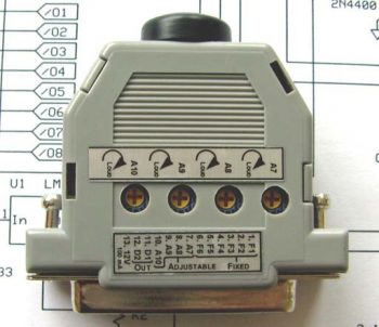
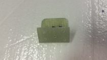
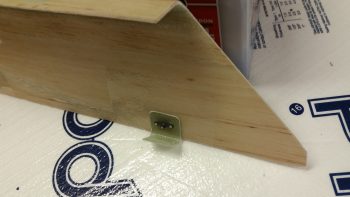
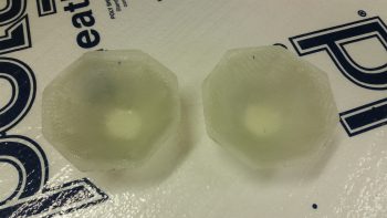
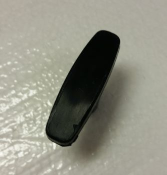
Here’s the type of handle that I used (it’s the same make, but a different handle than I actually used).

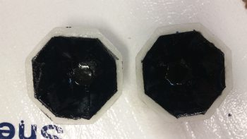
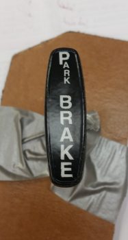
And here’s the same handle type after I labeled it with rub-on lettering.  The letters weren’t perfect when I went to clear coat it, but moreover, some loose edges (unbeknownst to me at first) were literally blown away when I hit it with the initial application of clear coat.  So, again, it’s clearly not perfect or as nice as it started out (or that I would prefer!), but it will definitely work as intended… at least for now.

As for the clear coat itself: I wanted to make sure that since this handle will most likely be subject to a fair amount of sunlight, and handled often, that the clear coat would stand up… so I shot 5 coats of matt clear on it.

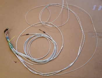
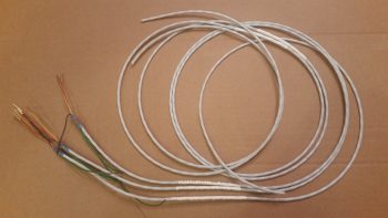
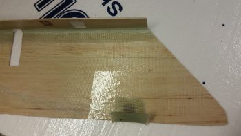
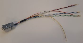
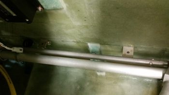
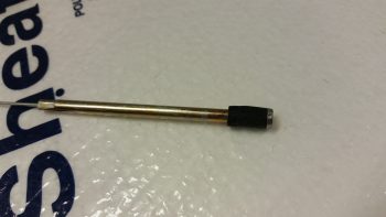
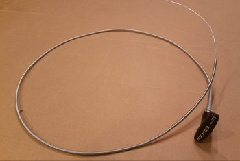
I then grabbed my comparatively lightweight cable assembly and handle –versus all the other T-handled cables I have on hand– and prepped it for trimming the handle down.  I bought this cable assembly at an auto parts store a while back since it was so lightweight, but I wanted a T-handle that would allow both more (“easier”) gripping power & enough top surface area to label it.

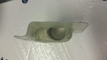
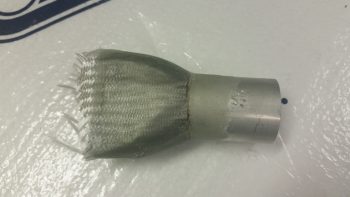
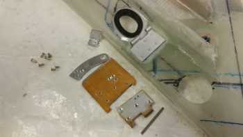
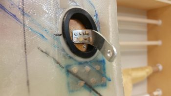
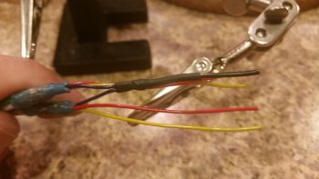
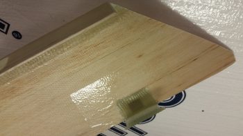
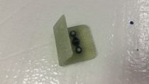
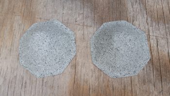
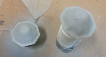
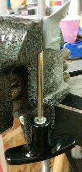
I grabbed my Dremel Tool and cut off the handle.  After removing the plastic handle material, it was then that I discovered that inside the handle was basically a round bolt head.

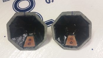
Originally I had planned on using the remaining plastic of the handle to secure the new handle in place with flox, but I then made the decision with the exposed round “bolt head” to cut as many 1/4-20 threads on it as I could to really help secure it in the new T-handle that I was going to mount.

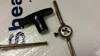
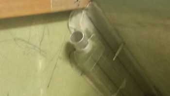
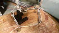
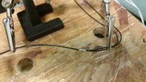
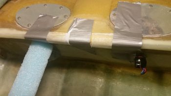
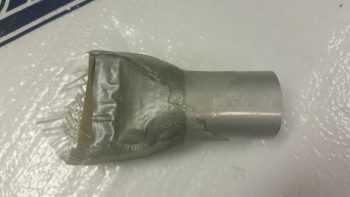
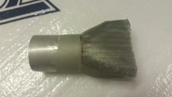
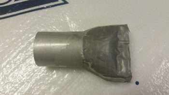
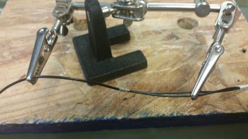
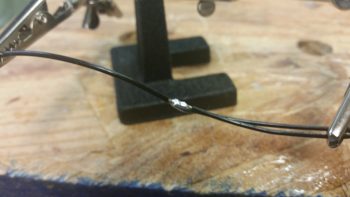
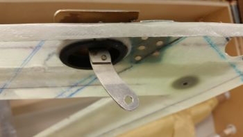
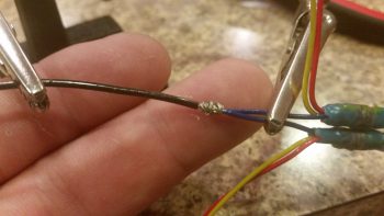
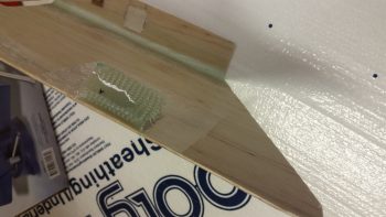
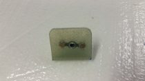
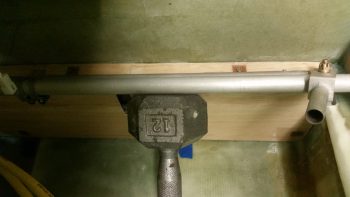
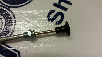
It was a bit tricky, but I was eventually able to use my die to cut a few 1/4-20 threads in the cable handle rod’s exposed round “bolt head” (yes, sorry for the pics!).

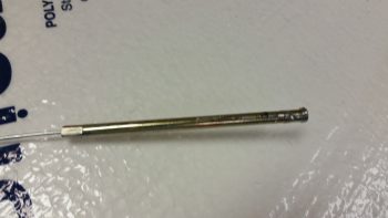
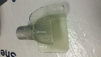
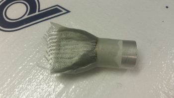
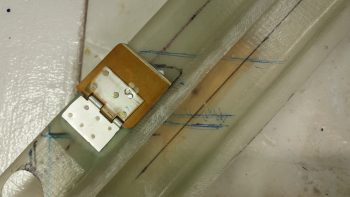
I then test mounted the freshly threaded cable handle rod and noted how deep the rod went into the handle.  I then cut a couple grooves in the handle rod just below the threaded head to provide gripping for flox.

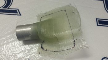
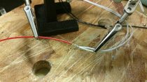
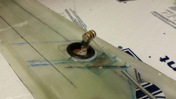
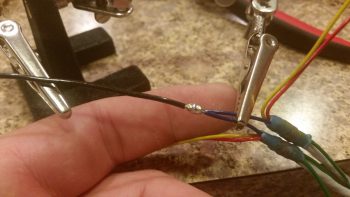
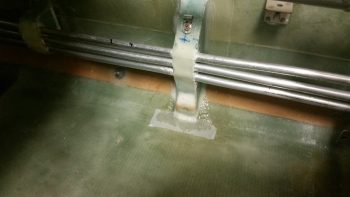
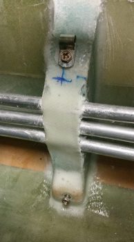
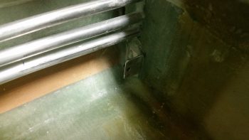
I then whipped up a small batch of epoxy with fast hardener, put a big drop of epoxy into the T-handle threads and threaded in the cable handle rod.  With the rod set & clamped in place (hanging upside down), I then whipped up some wet flox to fill in the remaining void between the handle rod and the T-handle threads.

I then left the handle & cable assembly alone to cure.

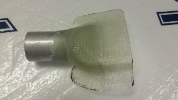
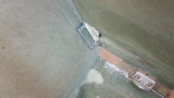
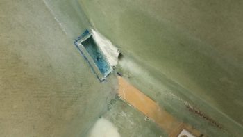
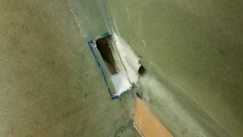
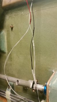
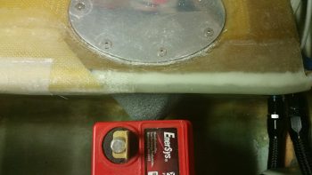
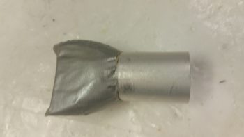
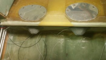
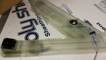
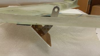
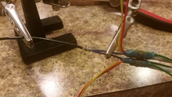
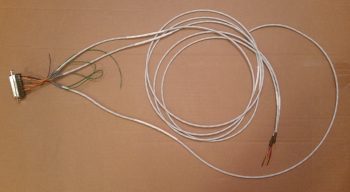
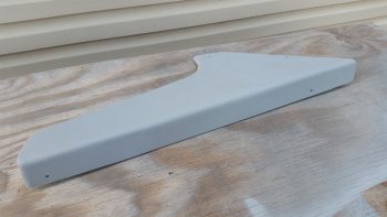
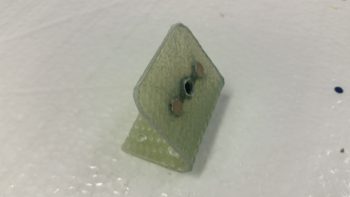
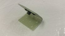
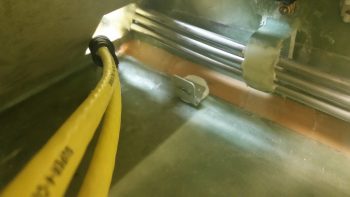
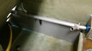
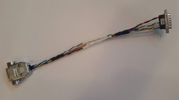
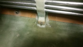
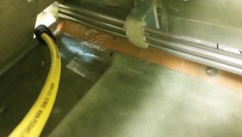
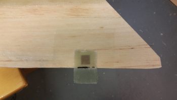
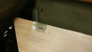
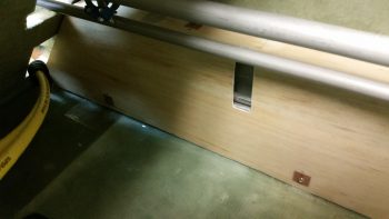
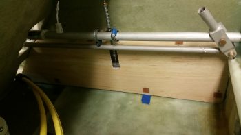
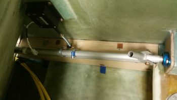
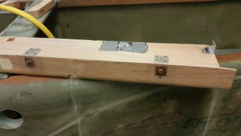
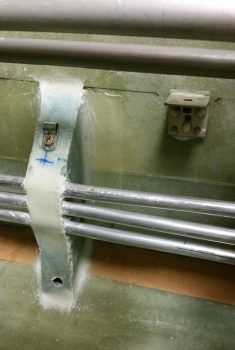
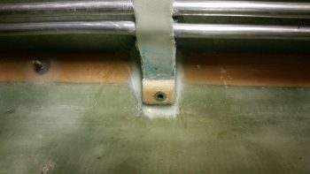
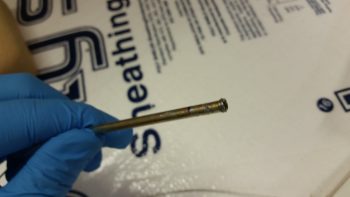
Finally, here’s a pic of the parking brake handle floxed in place on the cable assembly, with the cable assembly installed in the cable assembly sheath.  At this point the parking brake cable & handle assembly is ready for install.  As for the weight, the entire assembly shown below weighs 4.55 oz. (0.29 lbs) whereas my stock T-handle cable from Aircraft Spruce weighs in at 13.85 oz. (0.87 lbs) . . . a whopping 67% heavier than the T-handle cable I just made.

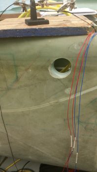
As is often the case, I didn’t get nearly as much done as I had planned on today.  But, getting this parking brake handle labeled somewhat successfully and installed on the cable assembly was a fairly big task that I can mark as completed.  Again, it may seem that my timing is a little odd, but I need at least one T-handle assembly completed to determine both the correct placement for the handle and the required structure to build to house the parking brake and nose hatch release T-handles that will reside on each side of the nose gear wheel well viewing window.  In addition, this housings for these two handles will bracket the fuel tank selector valve.

With this seemingly sideline task out of the way, tomorrow I can get back to working on the GIB fresh air & heating duct valve #3: the PIC & GIB air distribution valve.


Chapter 22 – Intercom Wiring Harness

Today I was still feeling pretty wiped out from my world wind trip down to North Carolina and Virginia Beach, so I took it kind of easy.  As I was doing some domestic cleanup duties I ran across a book on Burt Rutan that my son gave me as a gift, so I spent a good hour or so reading that . . . a little inspiration for the build!

After reviewing a bunch of pics I took of Marco’s firewall and engine compartment, and researching a bit while looking at some other folks’ firewalls, I then reworked the component diagram I have for my firewall.  May seem a bit ahead of the game, but if all goes right I will be mounting the firewall to the fuselage for good here in the next few weeks, and I wanted to figure out internal hell hole (aka “firewall forward”) cable & wiring runs, oil heat line configuration, and component placement.  Obviously, figuring out a close estimate of where all my firewall transitions will be on the engine side of the firewall will drive the placement requirements on the hellhole side of the firewall.

In addition, as I install the canopy I will construct a GIB headrest assembly that will also be a compartment containing the GRT EIS4000 engine management control head and the Electroair Electronic Ignition controller as well.  Having a good idea for where & how these component wires transit the firewall is a good thing.

Still in the electronics mode, and not feeling up to snuff for shop work, I worked a couple more connections on my Dynon Intercom wiring harness.  Specifically, I prepped and terminated the 22AWG 2-conductor shielded cable for the Mic connection from the intercom to COM1 (GNS-480).  Using the opposite end of the same 2-conductor cable, I also prepped & terminated the connection from the Intercom’s auxiliary audio input to the VX-Aviation AMX-2A 10-Channel Audio Mixer (see below).  I also printed out & labeled these new Intercom wiring harness cables with heat shrink labels.

I’ve been kicking around the need for an audio mixer for a while now, but the reality of this requirement hit me as I was helping Marco with his panel upgrade on his flying Long-EZ.  If there are more audio inputs coming into the Intercom from such devices that I have on hand like the Trio Autopilot, GNS-480 NAV & system audio outputs, etc. then an audio mixer is required to get them into one signal.

So, I finally made the decision to research out what I needed and make a final decision on what model would fit my requirements.  The end result –which I’ve had my eye on for a while– was the VX-Aviation AMX-2A 10-Channel Audio Mixer.  Apparently, Vern at VX-Avaition doesn’t sell these any more and has handed over sales control to makerplane.org, which is where the pic below is from.

As you can see, the form factor for this 10-channel audio mixer is a modified 25-pin D-Sub connector so the unit is very small and lightweight.  I don’t need it just yet, but it is on my list of stuff to buy so I’ll most likely order one in the next month or few.

In addition, I finalized my decision on the AMX-2A by incorporating it into my Comms wiring diagram.

Tomorrow I plan on getting back into the shop and turning & burning to get the cockpit stuff knocked out to get on with finalizing the nose build and getting the canopy installed.


Chapter 22 – Heat/air ductwork

I started out today by pulling the GIB duct transition for the upper vent off the tape form and marking it for trimming.

I then trimmed it with the Fein saw.

Here’s the underside of the GIB duct transition for the upper vent.

And the view from the rectangular sidewall duct heading into the vent tube transition.

Here it is set in place on the sidewall duct.  Again, I’ll be able to tweak its final position as I install the vent sidewall console.

Keeping on the duct theme, I then marked the position of where the duct traverses the pilot seat back in the lower left corner.  I then drilled 4 pilot holes for the corners of the rectangular duct hole.

I got the front side glass cut out using the Fein saw, then razor knife & then removed the foam.

I then cut out the aft side glass, cleaned up the hole and micro’d the edges.

As the micro on the duct pass-thru hole cured, I then got to work tying the respective left & right side GIB LED floor lighting wires together (white, red & ground pairs) into one lead.  I used solder splices to take the 2 right & left leads into a single wire lead.

I then covered the solder splices with protective heat shrink tubing and labeled all the GIB LED floor lighting wires.

I then tested both the white and red LED light pairs. They may look quite dim with the lights on, but with the lights shut off –as in a dark cabin– these things give off plenty of light.  And I should add: NOT blinding lighter either.

I then was finally able to get around to cutting the slot in the forward end of the Heat Exchanger inlet duct for the fresh-cool-air/heater-air valve control arm.  I then mocked up the heat exchanger mounted inside the GIB area with the air ductwork in place.  Also note that I have the upper GIB vent duct transition in place as well.

Here’s a closer shot of the oil heater heat exchanger.

I then wanted to get a shot showing how thin my entire ductwork and heat exchanger mounting is.  Of course, here I have to give a shout out to Nick Ugolini for R&D’ing the appropriate thin-line roll-your-own ducts.

Over the next few days I’ll be dealing with out-of-town visitors, then once I again I am heading to North Carolina until the end of next week.  Once I return, it should be 100% all go on the plane build until RR 2017.

So . . . see you next week!


Chapter 22 – It… all… matters…

Today I actually started off adding a couple of more shielded wires to my Dynon Intercom wiring harness connector (no pics).  With the 2 wires I knocked out today, that puts me at about halfway done on that harness.  In fact, I’ve got one more wire to add and then I’ll call it done until final install.  Why?  Well, the majority of the remaining intercom harness wires come in from the relay that controls the COM1/COM2 selection functions for the intercom.  And I can’t wire that up until I’m close to going live.

I then started back in getting the jacked up situation from yesterday straightened out.  I decided to bite the bullet and simply add another 3/16″ piece of Nylaflow –which will carry 3 wires–  from the left sensor cover over to the right and then a 1/4″ piece of Nylaflow –which will carry 6 wires– from the right sensor cover over to the right sidewall where the wires will merge into the small wire bundle that traverses the side of the fuselage.

I measured out what I needed and cut a piece of Nylaflow.  I then dry micro’d some around the Nylaflow to attach it and glassed in a ply of BID over each end.  I have to tell you, even this endeavor was just being a royal PITA! [I 5 min glued it the front wall but for some reason it just did NOT want to stay in place . . . ]

After much wailing and gnashing of teeth, I finally got the Nylaflow settled in close to what I wanted and after each end was cured, I then glassed a single patch of BID in the middle to finish off the 3/16″ Nylaflow conduit install.

I installed the left sensor cover in place using 5 min glue on 2 adjoining sides and silicone RTV on the other 4 (It’s hex shaped).  I then used my main battery to keep it in place while it cured.

A little while later, after the middle patch of BID cured, I then micro’d and glassed in the second piece of Nylaflow conduit, only this one was 1/4″ as I mentioned above.  I also used 1 ply of BID as I did before.

Even more of a while later I then 5 min glued & RTV’d the right sensor cover in place.  To be clear, I tested the LED lights in each sensor cover before securing them in place.

I will say that with this smaller Nylaflow conduit sitting right below the 3/8″ Nylaflow above it, the lip created by the top big Nylaflow conduit complete eclipses the lower conduit and you just can’t see it.

BTW, I’m covering the pictures by subject in this post versus jumping back & forth, but in reality I did go back on forth on these tasks.

During cure times above, I took a piece of urethane foam and shaped it to create an exit duct out of the top of the main duct that moves the air to the GIB upper duct vent.  I cut a piece of 1.25″ diameter 6061 tubing that I ordered specifically for these ducts… mainly because that’s the diameter of the eyeball air vents that I have on hand.  In addition, I also ordered some Skeet tubing as well, but it’s on back order with ACS.

I then prepped the foam for glass using duct tape.  I of course left the 6061 tubing clear since it will become an integral part of the upper duct vent transition.

Since the air will curve a bit “up” (all relative here) coming out of the duct, unlike the lower GIB duct vent, I decided to create 4 sides to the duct transition (transition from the fiberglass duct to Skeet tubing and then to the eyeball air vent) so I needed to get the “bottom” of the duct transition glassed first.  Thus, I glassed the bottom with 1 ply of BID and peel plied it.

After the BID cured I pulled the peel ply.

And then trimmed the glass.

Here you can see both sides of the upper duct transition vent.

I then set the initially-glassed duct transition vent in place in the top of the main duct channel and taped it up in prep for final glassing.

I then laid up a small ply of BID just over the top of the foam piece area (taped) for strength, and then laid up a ply of UNI and a ply of BID to create an overlapping flange on the existing duct.  I of course could have created the entire duct transition piece to fit inside the main duct channel, but I wanted to optimize airflow as much as possible.

And here’s a bigger picture view of the GIB upper duct vent transition and the rest of the duct network.  If you’re thinking maybe the duct transition piece is a bit too high, you may be right.  But I’ll be able to adjust the height through trimming down the aluminum tube length and/or hacking off some of the main vent channel if need be.

Here’s a bit clearer shot of the fresh air / heater air valve with the control arm clearly visible.

Tomorrow I’ll continue to work on my GIB area tasks.  As you can see, I’m nugging it all out and getting significantly closer to being done in the back seat area.  That being said, I will be receiving out of town visitors late tomorrow night. They’ll be here until Sunday, at which point I’ll be heading back down to North Carolina for nearly a week.  However, when I return I should have no further distractions until I head out to RR.


Chapter 22 – Piece of cake!

Yeah, not so much!

I started off today running around doing a million errands.  When I returned home I tested out one of my ELS-950 sump low fuel level sensors.  Here’s a video showing how it works.

With my sensor function test good to go, I then applied a light ring of Permatex 80725 around the threads of each sensor and then installed them into their respective ports on the vertical face of the thigh support fuel sump.

Here’s a wider angle shot showing where the sensors are situated on the front of the sump front wall.

I then taped up the sensor wires to keep them out of the way for when the covers are installed.

I then added a spot of tape to the aft ring of each sensor cover and mocked them up in place.  Looks like they’ll fit just fine.

I then spent a fair bit of time labeling all the left and right sump low fuel level sensors’ wires.

I combined the 2 sensor ground leads into 1 wire by solder splicing them together.  Here they’re prepped to be soldered.

And here the ground wires are solder spliced with a lead leading to the Triparagon.

After the sensor wires were all squared away, I then attempted to run 2 wires from each of the floor LED lights embedded in the sensor covers through the conduit on the face of the sumps . . .  the same Nylaflow conduits that I had just run the 3 sensor wires through.  I had tested this out earlier and there should have been plenty of room for 5 wires, but the wires just weren’t to be routed no matter how hard I tried or what method I used.

This was one of those tasks that every step you take to remedy the issue, the problem keeps getting bigger and wider, kind of like a big ‘ol pile of horse crap.  After messing around with the wires, my attempts to reroute them in my GIB headset jack conduit (I could spend 4 big paragraphs just on that cluster alone!) was to no avail.

So I punted.  It was late and I just didn’t want to screw anything up ( . . . further).  In short, out of the myriad of tasks I had planned to knock out today, I got about 3/4 of one complete!

Yes, so tomorrow will be about completing the other GIB area tasks I had planned for today!


Chapter 22 – Cheat when you can!

I started out today by cleaning up the inboard face of the heat exchanger by sanding the edges of the added upper & lower ducts where they overlap onto the main assembly.

I then cleaned up & prepped the heat exchanger for glass, or actually for 1 ply of carbon fiber.

Here’s the ply of carbon fiber after I laid it up and peel plied the edges a bit to ensure it stayed in place.  I didn’t go with the traditional super sexy carbon fiber look, since the reason I’m adding the carbon is I believe that with this heat exchanger being inboard of the ducts, it will get rubbed on with legs, knees, small marsupials, etc. over the years.  If it was painted, as I’ve seen with many a canard, over time the paint would simply rub off.  I wanted something that would not only be a good contrast with the gray granite paint that I’m using for the cabin, but that would be hardy enough that it would withstand getting rubbed on over the years without discoloration or deterioration of the surface.

I used fast hardener so a few hours later I trimmed the carbon fiber and got the heat exchanger pretty much back to the way it was before, just with a ply of carbon fiber on the face of it.

I wasn’t sure what I was going to do with the aft end, I just knew I didn’t want to attempt making my layup infinitely more difficult by trying to put carbon fiber here and wrap it around.  Admittedly, my original plan was to get much closer to the edge but the carbon fiber apparently had other thoughts on the matter.

With so much stuff to get done on this plane, I punted and went with the 80% solution to get this thing in the done column, and simply painted the aft end . . . In the grand scheme of things I don’t think anyone will really notice that the aft “face” is painted black.

I then got to work on the fresh air/heating air routing valve.  Below is the valve assembly in its component parts, ready for assembly.

And here’s after I riveted it all together . . . the second time!!  You see, the valve hinge had to go in first before I riveted all the main pieces together.  So of course I went to Tahiti for a few minutes in my mind while I riveted the first couple of rivets to get it all together.  My fault, but what a royal PITA to drill those rivets out.  Plus, it widened the holes a bit so I used a bit longer rivets and merely mashed harder!

Ok, so she ain’t perfect, but it looks like this dog will hunt.  The one thing I’m not overly happy with is the height of my valve, since it’s taking up valuable space in my duct and reducing the duct’s cross section for airflow by almost 0.5″.

Here’s a shot to see where this valve is in relation to everything else.

And here’s a few shots of the valve and the attached control arm.

I then added a cable mount bolt and a cable to test out the function of the valve.  It’s simple and I don’t think there should be any issues (besides having to trim down the upper edge of the valve since it’s just a hair wide.)

With my ductwork tasks done for the evening, I focused on getting the cable runs to the GIB headset jack squared away, primarily at the Dynon Intercom harness connector.

After doing over an hour’s worth of research and brushing back up on the intercom wiring, I then cut the wires to length, stripped the wires and then added shield grounding pigtails by using ground solder sleeves.

The pilot and GIB Mic/PTT wires share a common ground at Pin 2, so I went ahead and did a solder wire splice to add a small length of 20 AWG wire to the 2 shielded wire ground wires.  BTW, I used the Bob Nuckolls’ technique for solder splicing 2 wires together.

Here’s my soldered wire splice.

I then added a piece of shrink wrap over the soldered joint.

Here’s a shot of my Dynon Intercom wiring harness . . .  so far!  You can see that I labeled the main cable insulation and terminated the individual wires with the included D-Sub sockets.

Wrapping up the evening, I terminated the sockets into the Dynon Intercom 25-pin D-Sub connector.  I also stripped and heat shrank the GIB headset jack ends (the sides in the left GIB armrest) of the cables in preparation for installation.

Tomorrow I’ll continue to work on knocking out all this extraneous build stuff so I can get on to the nose, canopy and strakes.


Chapter 22 – Back in back

Today was one of those days where I was in full build mode all day long, but then at the end of the day it felt like I hadn’t done much.

First off, once again the nice man in the brown truck (UPS) brought me more airplane parts… Today I got the COM1 and XPDR antennas that I ordered, terminated with the appropriate fittings. One more thing off the list!

I started off on the actual build by drilling a few sets of tiny holes to inject fresh epoxy into some air bubbles along the joint of the front extension pieces that I had glassed onto the left GIB armrest.  This armrest is definitely the ugly duckling of the armrests, and admittedly looks pretty nasty where I glassed the front extension pieces into place (I was originally planning on having a throttle handle back here, but then realized first that it was located too far aft, and then second, that I simply wasn’t going to install one).

That’s why it’s so cool, and so much fun honestly, to see it turn out like this with just a few passes of a primer spray can.

I let the primer cure for a few hours, cleaned up and sanded a few minor imperfections, then shot two coats of the gray granite interior paint.

I then let the topcoat cure for about 6 hours before shooting it with a couple coats of matt clear coat.  A little over an hour later, when it was dry to the touch, I set it in place to get the pics below.

I have to say, I’m really digging this color.  It’s not super flashy nor does it make a huge fashion statement, but it really does look good.  And of course, as I often state, the pics don’t do it justice.

Although I documented my painting sequence on the armrest, it’s not all I did today, nor was it the primary goal on my task sheet.

I don’t have any pics showing my progress, but today I actually determined the size and shape of the valve lever arm for the heating/air system.  This valve is the one that will determine whether incoming fresh air is left alone to be routed through the ducts for cooling air, or diverted to the heat exchanger for heating air.  I cut out, shaped and cleaned up the pieces to ready them for install via flush-mounted rivets.  I was getting ready to drill the holes for my rivets when a buddy called and I ended up meeting him out for dinner and  a couple beers.  So… I’ll get some pics of my heating/air valve work tomorrow.

In addition, as I was trying to consolidate my metal cutting tasks, I had on my list to cut an L bracket for mounting under the Matco parking brake to secure the brake’s ON/OFF actuator cable (with an Adel clamp).  As I was trying to finalize the dimensions on that bracket for cutting –remember, I have to pull saws out of an outside shed so I like to cut all that I currently have on my list at one time for efficiency’s sake– I determined that I don’t need a bracket at all, just some 1/4″ Nylaflow and a click bond mounted on the left side NG30 plate and I’ll be good.  So, check the parking brake cable install design off the to-do list as well! [Note I said install design, and not the install itself].

Again, tomorrow I will continue to work on the GIB area stuff, with the heating & air system valves my specific priority until I get those finished.


Chapter 22 – Kick plate finished!

Today I started out by pulling the GIB kick plate out to check the forward mounting bracket layup.

The mounting bracket looked good with the angle appropriate to how the lower corner of the cockpit is shaped.

I could tell by the bottom of the cured mounting bracket that not all of it was in contact with the taped fuselage corner . . . I guess gravity isn’t what it used to be!

I first drilled the #8 screw mounting hole through the kick plate and part way through the forward lower bracket when it decided to remove itself from the kick plate.  I then drilled and riveted a K1000-8 nutplate to the mounting bracket, and then trimmed all 4 bracket sides with the Fein saw.  Finally, I drilled anchor holes and sanded the bottom of the mount that will get floxed to the fuselage corner.

Here’s a few pics of the completed forward kick plate mounting bracket.

I then remounted the composite forward mounting bracket onto the kick plate.

Knowing that only a small portion of the mounting bracket had been in contact with the cockpit corner when I set it, I slathered it up with flox before remounting the kick plate.  I used fast hardener… so a few hours later after it cured I pulled off the kick plate to find that my mounting bracket floxing endeavor was successful.

While the kick plate mounting bracket flox was curing I took my fuel sump low fuel level sensor covers outside and painted them with the Rustoleum granite paint that I will be using for the interior cabin paint.

While the fuel sump low fuel level sensor covers’ paint was curing I called Mike at ACK to go over my ELT install configuration.  He gave me some very key information that will be very pertinent to my ELT installation.

I then determined the size of the phenolic LED light mounting reinforcement plates, cut them and then 5-min glued them into place (after I removed the paint and sanded the glass where they were mounted inside the covers).

I then determined where the 2 LED holes would be situated, then drilled the holes.  I tested out the angle of the LED light beams, so when I drilled the holes I made them a bit more horizontal in comparison to the aircraft waterline.

With the LED mounting holes ready, I then prepped the LED lights for mounting by soldering the red & white LEDs and wires, including a 470 Ohm resistor on the shared ground wired.

I then added heat shrink to secure & protect the solder joints.

Although the pic below looks like you’re looking down into a fiery volcano, I included this representative shot of the red LED test lighting.

Here’s the white LED test.  Again, the light showing up in these pics is more drastic, contrasting and harsh than what is really viewed in person.

Here are another couple shots of the sump low fuel sensor cover LED floor lights from the front, facing the camera (which I shot at an angle so they wouldn’t “blind” the camera).

Again, this is a representative view of the red & white LED lights glued in place into the right sump low fuel sensor cover.  The left looks pretty much the same of course.

Concurrent to the work I had been doing on the LED floor lights, I also primed & painted the kick plate with my gray cabin granite paint.  Over 4 hours later I hit it with a couple coats of matt clear coat.

This is about an hour later after the clear coat was dry enough to set the kick plate in place  to get this pic.

Here’s another shot of the painted and clear coated GIB kick plate.  BTW, I checked the weight of the kick plate just prior to painting it and it weighed in at a whopping 5.8 ounces.

Tomorrow I’ll continue my quest to finish all things GIB before moving on with other parts of the build.


Chapter 22 – Play Time is Over!

No more electrical stuff for me… back to the GIB area!  Ok, except this one sideline task. HA!

Today I started by finishing up annotating the J3 PQD connector color codes, which of course meant digging in the GRT Mini-X manual and also seeing what the wire colors were that I physically had on hand.  Since I had the Mini-X wiring harness (15-pin D-Sub) in my hand, I decided to go ahead and knock out the wire harness connector for my Mini-X.

First, I had to pull a few wires for connections that I won’t be using.  These few specific wires came installed on the GRT-provided 15-pin D-Sub connector/harness.  I measured the required wire lengths between the back of the Mini-X and the J3 PQD connector on the Triparagon.  I added a couple of inches for ‘insurance’ purposes and another half inch to account for the multiples pairs that would be twisted together, then ended up cutting all the wires down to 10.5″ long.  I then crimped some D-Sub sockets onto 3 wires for the magnetometer (since it’s optional) and terminated them into the Mini-X D-Sub connector.  I then twisted the appropriate wire pairs together using a small portable drill.

I then terminated the ends of the wires with D-Sub pins on the opposite end from the Mini-X connector and performed a continuity check on each wire… all good.

Then, on the Mini-X side of the harness I installed the D-Sub backshell.

Having also just received some more correct-sized wire labels, I then labeled the 2 individual wires and the 3 wire pairs.

For the panel component labels that run ONLY between the panel components themselves, or the panel components and the PQD connectors, I’m using a bit more simplified wiring label scheme than the one I use for the rest of the plane: essentially providing just a pin number, the wire function such as “power” or “DU link” and an opposite pin number, all separated by dashes.  Obviously, on the panel I’m looking at the wire runs from the back of the given device and seeing its termination point just a scant few inches away… all the info is there for me to see straightway, except the pin #’s and wire functions. So, for example, the lone magnetometer signal wire label goes like this:

10-MAG SIG-9

Pin 10 on the Mini-X EFIS D-Sub connector, the truncated description as to the function of the wire, and Pin 9 on the J3B PQD D-Sub connector.  Short and sweet.  If a twisted pair is getting labeled, I simply add both pins on each side separated by a “/” (aka 11/12).  I’m still sticking with the more robust label scheme throughout the rest of the plane which allows me to determine where the wire is coming & going, what devices it goes to (points A & B) and what pins it connects to at each end (typically power, ground or data signal).

Here’s a shot of the Mini-X wiring harness, minus the D-Sub 15 backshell (which is on order) for the J3B side.

I then set my sights on finalizing the GIB right side kick plate mounting.  I started by stuffing some plastic saran wrap into the aft lower hardpoint screw hole, and then laid up a ply of BID over it.

A few hours later it was really close to being cured, so I hand drilled the hole through the glass in the front to remove the plastic.  I then cleaned up around the hard point screw hole and test fitted the screw.

Here’s another wider angle shot of above.

I then spent a bit of time sanding down and cleaning the fuel sump low fuel sensor covers.

Here’s the exterior side of these things . . .  After sanding, I then gave them a good Simple Green wash and dried them off.

I then taped up the interior edge of both sensor covers and then shot them with a couple quick, light layers of black paint.  I would have preferred to use matt paint, but I only had gloss on hand so they’re a bit fancier than I had intended.

I then prepped both the outboard side fuselage area and of the interior wall of the kick plate with clear packing tape to keep the composite bracket from gumming anything up.

I then set up 2 prepregged 3-ply BID layups.

I then wet out the prepregs and combined the 2 stacks of 3 plies to make up a 6-ply forward kick plate mounting bracket.

I then laid up the 6-ply bracket layup half way onto the forward kick plate mounting hardpoint.

I then folded it back on itself so that it was almost touching.  My goal here was that when the kick plate was mounted, gravity would simply pull the glass down onto the protective tape on the floor, creating the exact correctly shaped bracket blank –since the floor at the corner here is 45°– after it cures.

Here’s a shot of the entire kick plate, with the 6-ply mounting bracket glass formed on the inside.  I was able to get just a peak of it through the holes in the front seat bulkhead and from what I could ascertain, my “shot in the dark” layup looks ok.

As the kick plate bracket glass cured, I then took a quick opportunity to apply a couple of coats of gray primer onto both thigh support fuel sump low fuel sensor covers.  Since I’ll have a pair of LEDs poking out the bottom of each of these covers, I wanted to get them painted so as to not have to worry as much about taping off those LEDs, which again will be on the bottom side, when I paint the rest of the back seat area.

Tomorrow I’ll continue working on all things GIB!


Chapter 24 – Kick plate mounting

Today I started off by finalizing the cleaning up & initial round of micro’ing some divots I had made (during cleanup) and the minor gaps between the wood pieces on the GIB right kick plate.

I then let the micro cure a bit as I cut the BID and peel ply for the layup.  I then laid up the 1 ply of BID using MGS 335 with fast hardener.

I then peel plied the layup.

I then took a break, grabbed something to eat and uploaded my pics to this website.  A bit later the layup was cured so I razor trimmed it, pulled the peel ply, cut the notch for the roll trim spring assembly, and then test fitted the kick plate in place.

It took a few iterations of trimming both the front and the aft edges of the kick plate to allow it to slide into place, but I eventually got it to settle in quite nicely.  Towards the front side top you may notice a square patch where I cut out the interior glass and wood to thin the top out for clearance with the underlying Adel clamp.

I then made up a brand new 6061 mounting tab for the aft edge and riveted a K1000-8 nutplate to it.  I also riveted K1000-8 nutplates to some existing mounting tabs I had made up earlier for the armrests.  I then added some protective tape around the mounting holes and mounted the brackets with #8 screws.

I then whipped up some flox, floxed up the 3 mounting brackets and set the kick plate in place.  To ensure the brackets were pressed into place nicely, I rested a weight against the kick plate.

A bit later, after the flox cured, I pulled the kick plate off the installed mounting brackets and cleaned the protective tape off of the kick plate.  Here are the 2 upper mounting brackets floxed in place to the fuselage sidewall.

And here’s the kick plate’s aft mounting bracket floxed in place to the front thigh support sump front wall bulkhead.

Before I pulled off the kick plate I drilled an 11/64″ hole through the bottom aft phenolic hardpoint in the kick plate.  I then widened it out in the fuel line bracket to accept a RivNut hardpoint that I’ll use for this mounting point.

I cut a few grooves into the RivNut to add some gripping power and taped up the end with duct tape.

What’s not seen here (you’ll see it when I remove the kick plate) is the 1/4″ thick Divinycell foam spacer that I floxed into place between the kick plate interior side and the fuel line mounting bracket.  The inboard half of the RivNut is floxed into the foam spacer while the rest of it is floxed into the fuel line mounting bracket.  The spacer itself is floxed on the outboard side to the face of the fuel line mounting bracket.

Later, after the RivNut & foam spacer flox cures, I’ll layup 1 ply of BID around the spacer to secure it and the RivNut to the fuel line mounting bracket.

I then used the same 12-pound weight pressed against the lower RivNut hardpoint (and foam spacer) to keep it securely in place.

After I finished writing the majority of this blog post, I went back down to the shop to catch the flox on the lower kick plate RivNut hardpoint in its “green” stage of curing –where it’s still just a little pliable– and I was able to do so [Incredibly easier when the epoxy/flox/micro is in this stage… it has the consistency of caramel candy and can be cut and removed without much difficulty].  I removed the screws and pulled the kick plate off its mounting tabs, and then cleaned up the flox that had oozed out from around the sides of the 1/4″ Divinycell spacer.  Here’s the (nice & clean) result:

Tomorrow (Sunday) I’m leaving for North Carolina for a few days.  Then I’ll spend a couple of days with Marco.  Thus, I will not be building (although I will place some orders!) during that time.  Once I get back I plan on working full bore —in maniacal fashion— without a break until Rough River.