Tooling Up: Fusion 360 CAD

After getting the lion’s share of my machining equipment and CNC conversion requirements, designs, and BOMs knocked out, I decided it was time to sink my teeth into learning some CAD…. specifically, what is arguably the standard CAD package these days: Fusion 360.

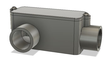
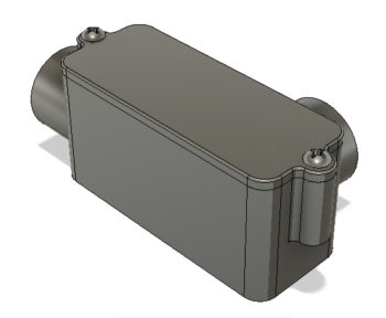
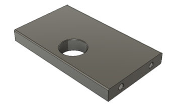
After downloading Fusion 360 and getting it running, I then spent a myriad of hours working through countless YouTube videos to start getting the basics down.  I really found Lars Christensen’s channel to be helpful and following his sage tutelage was able to create a CAD drawing of an electrical conduit box, shown below.

With my newfound knowledge, I then set out to create some drawings for the power drawbar that I will construct for my mill.  For an explanation of what a power drawbar does, I’ll defer to the excellent description my buddy Marco provides on his blog.  

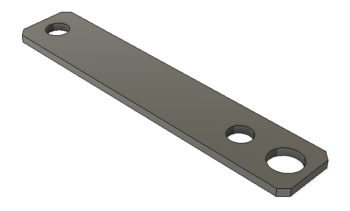
I started with a simple piece of the drawbar assembly and was pleased that I was able to knock it out in fairly short order.

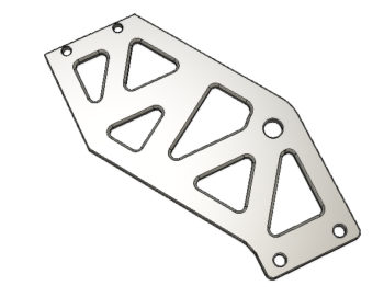
I then bit off a much bigger part that would allow me to employ some of my own creative ideas in creating a flat side plate of the pneumatic drawbar and punching triangular shaped holes in it.  It’s my first take on the side plate, and it could easily change, but so far I like what I have.

I then drew up the pneumatic drawbar top plate that has a mounting hole in it for the air cylinder that drives the drawbar levers down to release the Tormach Tooling System (TTS) tool holder.

I then had to put my Fusion 360 creative endeavors on hold for about a week as I ran out to Portland, Oregon to help my Mom with some medical stuff.  In addition, while in Portland I had to work a compatibility issue that cropped up that wouldn’t allow me to run Fusion 360 on my older MacBook Air.  

At first it appeared my only option to use Fusion 360 on the go would be to buy a new laptop, since on the face of it an upgrade to the latest Mac OS (Mojave) would crash my older MacBook.  After a few days of research I then discovered that I could simply upgrade my laptop to the Sierra OS immediately following the one I had installed, El Capitan.  I waited until I got home from Portland to clean and backup my laptop’s hard drive before updating my OS to Sierra.  

Once Sierra was up and running, Voila! my Fusion 360 was also back up and running.

Tooling Up: Future CNC

For a number of years my buddy Marco has helped me out with making stuff in the machining realm, be it metal or plastic . . . on the lathe, mill or 3D printed.  I’ve always greatly appreciated his fantastic work and wonderful help, but also had always planned on learning the magic of machining to facilitate not only creating components for my Long-EZ, but for many other projects as well.

Thus then, another recent segue in my build –stemming from my back injury (all good now) and subsequent house selling delay– was to prep for the upcoming onslaught of machining projects in the hopper that will need to be completed before my bird takes flight.  Yes, admittedly a good number of these required components are the result of self-inflicted mods and stylistic preferences, but regardless all these parts need to be completed for the plane to be completed as well.

The time finally came, as I knew it would, for me to knuckle and buckle down to get serious about my machining abilities, specifically in regards to learning CAD (Fusion 360) and having CNC-capable machines both on a Mill and Lathe (3D printing will follow shortly). Again, with so many components that need to be machined, I could no longer in good conscience ask Marco to take time out of his busy schedule to do the copious amounts of machining required to create my Long-EZ parts (not that he’d have the time to do them all anyway).

Since I had already done a fair amount of research on the CNC equipment side of the house, I decided to start there.  After returning from my holiday sojourns, and with my first scheduled instrument training flight nearly a week away, I decided to nug out the equipment and materials requirements for both my lathe and mill CNC conversions.

Since the mill is higher on the priority list –I do have my lathe on hand– I decided to start with it first.  In addition, since my mill will have 3 axes vs. the lathe’s simple 2 axes, it would be easier to par down the mill’s CNC electrical diagrams to convert them over for lathe CNC diagrams.

After a good 3 days of intense research, emails, phone calls and reading, my plan came to life at which point I captured over 90% of it all in 4 electrical diagrams.  Midway through the process of creating these electrical diagrams, a discussion I had with Marco sparked an epiphany of sorts at which point I decided to upgrade the machining mill I plan to buy from a Precision Matthews PM-25MV to a PM-30MV.  In short, the PM-30MV provides more travel in the X, Y and Z axes, and it has a more powerful 2 HP (vs 1 HP) motor that provides more torque and higher RPMs.  Lastly, the PM-30MV is much heavier, and is thus a more stable, rigid platform for CNC operations.

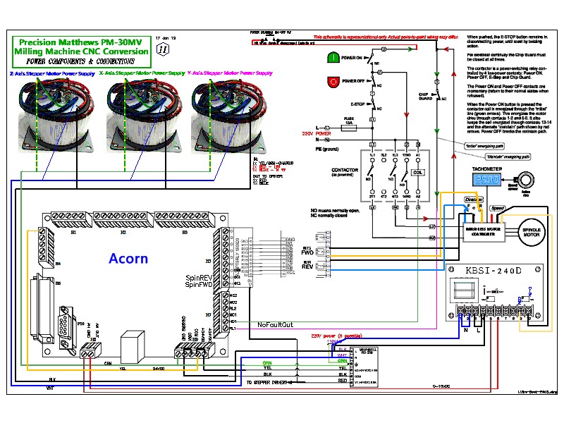
So without further ado, here is the first of my wiring diagrams for the CNC conversion of my (planned) Precision Matthews PM-30MV Machining Mill.

As you may have noted in the diagram above, I made a final decision on the CNC controller hardware and software with the Centroid Acorn system.  I also decide to “go ugly early” by ordering the first of my closed-loop stepper motors, which are much more expensive than the open-loop stepper motors (most common) but much more capable for CNC.  These closed-loop stepper motors use upgraded (again, in comparison) drives compared to open-loop stepper motors.

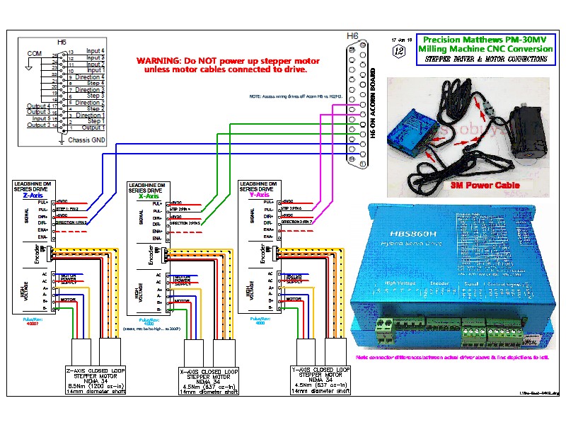
This diagram depicts the motor data connections between the Acorn board and drives, and also the data and power connections between each drive and motor.

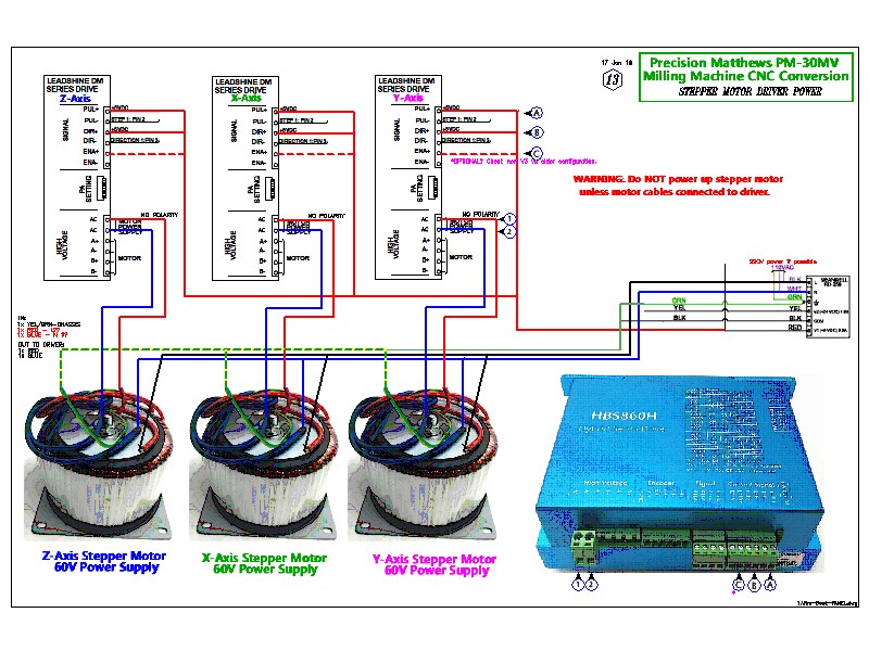
I then figured out the power circuits for the 5V and 60V power between the Acorn power supply, individual axes drives and axes power supplies.

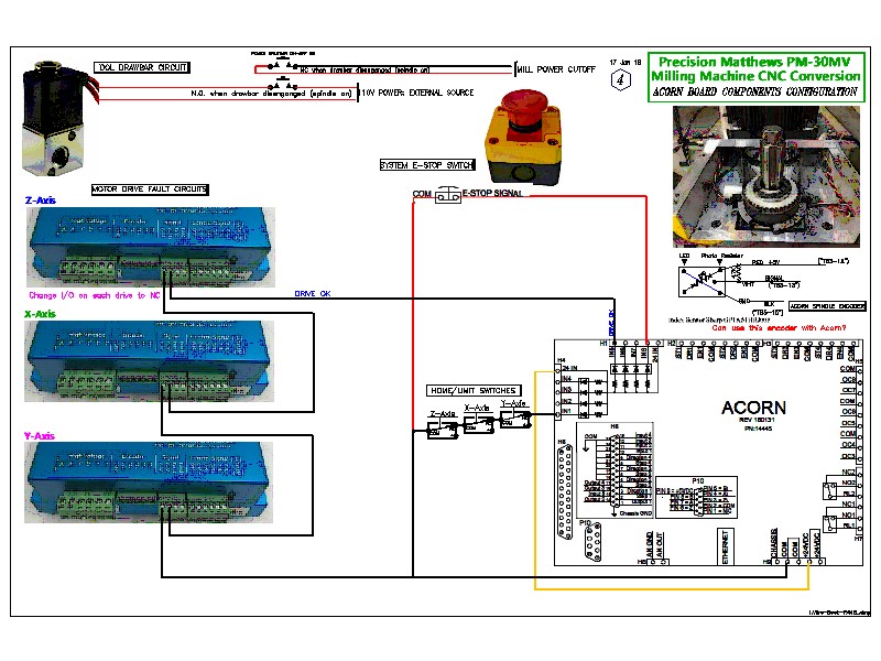
Finally, I made up a diagram to depict the remaining discreet components that make up the CNC system: power drawbar air valve, the E-Stop switch circuit, spindle speed encoder, drives’ alarm circuit, and home/limit switch connections.

Just fly it off!

As you all probably know, I’m in the slow process of moving down to the Cherry Point area of North Carolina. I had meant to be moved down there already, but schedules have a way of slipping to the right. Currently I have roughly 90% of my stuff in storage –including my Long-EZ project of course– down in NC.

I had been working on my DC-area house to prep it for sale, but about 6 weeks ago I tweaked my back pretty badly helping some friends move. Needing to recuperate for a good bit, I made the decision to delay putting my house on the market until early 2019 and to do what I can to finish up my Instrument Rating.

Over the past few weeks I got all the necessary stuff lined up (insurance, etc) and was able to knock out my Biennial Flight Review last Friday. Now current (i.e. ‘legal’), I have 2 instrument lessons under my belt with a bunch more scheduled up until Christmas, and a lot more to come after New Years.

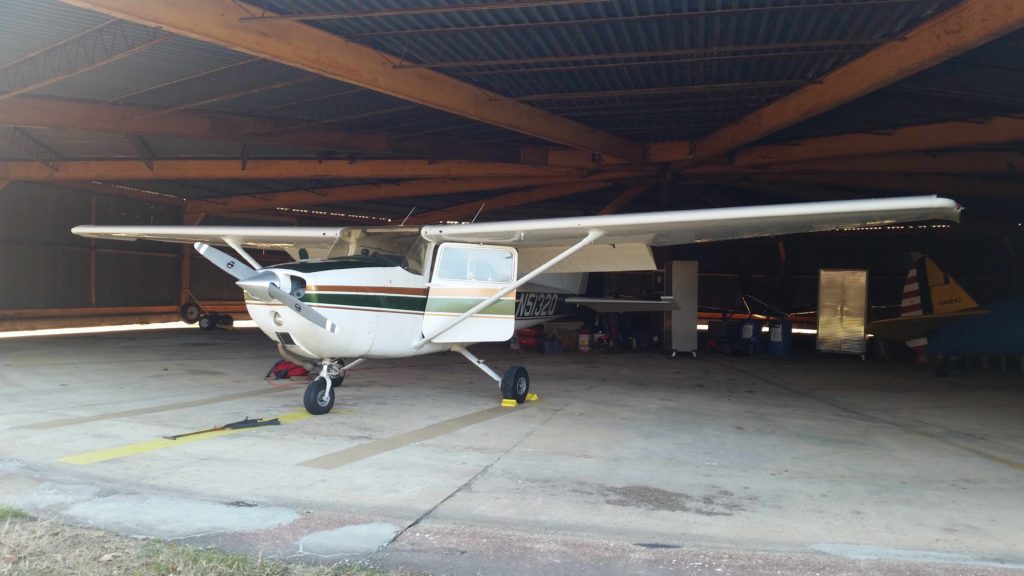
The pics are of a couple of the Cessna 172s (yes, “spam cans”) I’m currently flying for my Instrument rating.

Chapter 22 – XM Weather

Last night I had finished making both a long list of notes –including questions to ask different vendors– regarding my in-cockpit XM weather capability using my WxWorx receiver.  Overnight I had an epiphany on two fronts.  The first was that I resigned myself that I was only going to pipe XM satellite weather into my cockpit on one device: my Bendix/King AV8OR portable GPS.

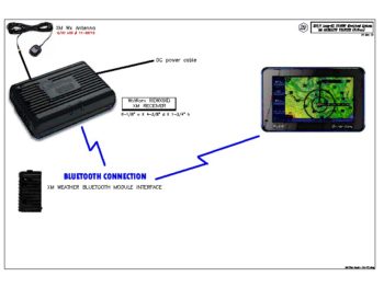
The second was that instead of messing about with trying to figure out how to purchase a nearly-impossible to find (original optional component) RS232 cable for a hard-wire setup between my XM Wx receiver and display (AV8OR), that I would instead look seriously at using Bluetooth betwixt the two.
You may be wondering why I’m not pushing to have my HXr EFIS display XM Wx data, and at first I was very much intent on doing just that.  However, having dug into the XM Wx display capabilities of GRT’s HXr EFIS, it honestly just doesn’t match up nearly as well in displaying various XM weather products as the AV8OR does.  Yes, although a bit older platform, the AV8OR simply beats out the HXr in XM Wx display at just about every turn (except display size).

The bottom line is that in my realization of the amazing & difficult number of technical/logistical hoops I’d have to jump through to get the XM Wx to display on both the HXr (fewer XM Wx products) and the AV8OR GPS (nearly all XM Wx products), I was driven to an undesired —but EZ— decision to go with just the AV8OR to display my in-cockpit XM Wx data.  To be clear, I will still display NexRad Wx data on my HXr EFIS, but just via ADS-B.

To provide somewhat of a full scope report, I will say that I discovered a device —Mobile Link— now offered by Baron (AKA “WxWorx”) that translates the XM Wx data across a WiFi signal to be used on up to 4 portable devices such as iPads, iPhones, and Android phones/tablets.  Upon a closer look however, I unfortunately discovered that Mobile Link provides an either-or solution, not an either-and solution in that I could either go the Mobile Link route for JUST a WiFi solution (mobile), or with my current XM Wx receiver to panel device solution (EFIS, GPS unit, etc)…. but not both.  Since it would cost much extra for Mobile Link, I decided not to go this route and will continue looking for more viable solutions to get XM Wx on my mobile devices…. specifically on my iPad for Foreflight.

In narrowing my target focus, I again decided to shoot for getting my XM Wx data solution implemented with the most elegant solution possible.  Although I currently have a USB cable connection on my XM Wx receiver, I still had a nagging question on just how exactly that would interface with my AV8OR GPS unit.  What I did know however, is that it would require an optional cable which I do not currently have on hand. Note, that “cable” here is also a significant, operative word.  The bottom line is the location and fit of my AV8OR on my panel is very tight, and introducing a new cable would add to its complexity of getting it situated on a tightly packed panel and its use (removing during non-use and during fly-ins, etc).

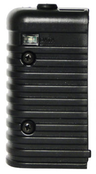
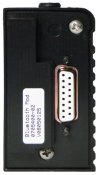
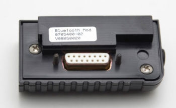
Although an unexpected expense, by purchasing the XM Wx receiver Bluetooth module from Aircraft Spruce, it knocks out the proverbial 2 birds with 1 stone: 1) It solves all questions about connecting device A (AV8OR) to device B (XM Wx receiver, and 2) it makes the install overwhelmingly much cleaner and easier.  So, I pulled the trigger on the Bluetooth module.

Fellow builders that know me know that I often use a term, half in jest, that it’s “better to be lucky than good.”  And as I’ve shared with you before, an old boss of mine used to so wisely say, “Luck is when preparation meets opportunity.”  Well, I think both of those came into play today since I was able buy literally the last Bluetooth module that Aircraft Spruce had in stock for a 2nd generation XM Wx receiver.

On top of that, since the Bluetooth module replaces the USB cord module it then goes to reason that another power source is required (since the USB cord provided it in the wired configuration).  Well, due to a note on the Aircraft item page for the Bluetooth module that some of these peripheral items may be available, after a short hold while the very helpful Aircraft Spruce sales rep called the company that makes the power cords, I was happy to hear that I would be allowed to purchase one of just a few power cords they had left… Woo-hoo!
With my initial XM Wx data solution seemingly resolved, I then pressed on to creating a wiring diagram for the Trig TT22 Mode-S transponder.  I have depictions of its install in a few other diagrams, but since I decided to place it in the outboard pocket of the right strake, I figured I had better expound a bit on the particulars of its wiring and installation. Thus, here is the resulting transponder wiring and installation diagram.
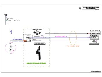
The transponder wiring diagram above is actually a significant milestone in my build, since it caps a near 5-year effort to document my entire electrical system and components into individual diagrams.  So, for those of you that are interested, here’s the latest updated list showing all my Electrical System Wiring Diagrams:

0. Index Page
Z.  Z-13/8 Electrical System
A.  Switches, Circuit Breakers & LEDs
.99 Grounding Busses
1.  Panel Components
2.  Radio & audio system
3.  Panel Power
4.  Electrical System Components Location Diagram
5.  Aircraft Wire Labeling Sectors Diagram
6.  Nose Gear/AEX System
7.  Pitch & Roll Trim Systems
8.  Lights: LDG, TAXI, NAV, STROBE
9.  Engine Info Management
10. Fuel System
11. Cockpit Lighting
12. Landing Brake
13. Throttle Handle Switches
14. Control Stick Switches
15. Integrated Backup Battery System & X-Bus
16. Gear & Canopy Warning
17. Charging System
18. AG6 Warning Annunciators
19. Electronic Ignition
20. P-Mag Ignition
21. Oil Heater System & Seat Warmers
22. Starting System
23. ELT
24. Heated Pitot Tube
25. Trio Autopilot
26. Video Camera System

27. Heads-Up Display (HUD)
28. Transponder
29. XM Weather
30. Long Wire Runs


Chapter 22 – New Wiring Diagrams

Yeah, not a lot going on as far as actual building, but I am getting some of the low hanging fruit –which does take a good bit of time– out of the way.

To start off, I did get my 15 amp mini-ANL fuse delivered.  Just for sake of closure here’s a shot of it installed in the fuse holder.

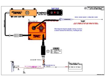
In addition, over the last couple of days I’ve created wiring diagrams for the ACK E-04 ELT:

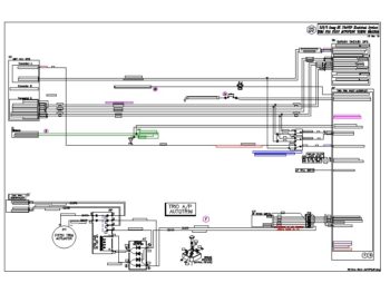
the Trio Pro Pilot Autopilot:

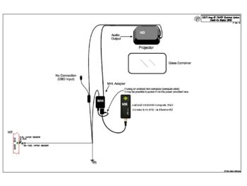
And the GRT HUD system:

I do have a bit of final cleanup stuff and crosschecking to do on each of these diagrams, but for the most part they are complete.

Finally, in the next few days I plan on knocking out the Trig TT22 Transponder wiring diagram, which at this point is the last wiring diagram left to complete.  Moreover, I’ve made updates and tweaked about 10 other wiring diagrams so my electrical system documentation is pretty up to snuff currently.

I’ll continue to update you all on any minor bits of progress or massive decisions that I make on the build as they occur!
 

Chapter 22 – E-Bus Feed Fuse

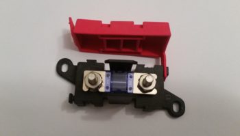
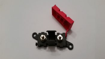
From my research this was the best Mini ANL (MIDI) fuse holder that I could find to serve as my new E-Bus feed fuse holder…. and I quite like it too.  It’s lightweight (1.4 oz) yet quite sturdy and simple in design.  As you can see, it has two #10 screw posts which each serve double duty to both retain each end of the Mini ANL fuse/current limiter and secure the respective wires’ terminals to the fuse holder.

The actual nomenclature for this component is the EATON Bussmann LMI1-E-2-0 Fuse Holder with Cover.

The attached red rubber protective cap simple pushes into place –with slots on the underside of the cap– onto the center vertical posts that are situated above and below the center fuse area in the pic above.

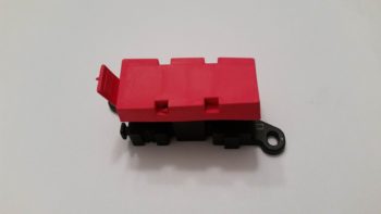
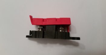
Below are pics with the red protective cap in place.

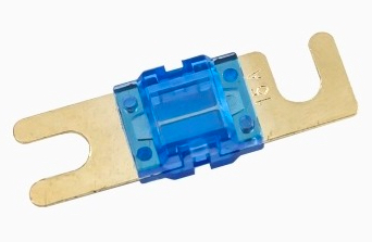
And here is a representative shot of the Mini ANL (MIDI) type fuse, which of course is just a smaller version of the more robust 40-60A current limiters often seen in many experimental airplanes on the alternator’s B-lead circuit.

I looked around at a couple of auto parts stores in hopes that they would have these Mini ANL (MIDI) fuses in stock, but alas, I ended up having to order them online.

So I now have all the components identified/on-hand/on order to make the modification in my conversion to Bob Nuckoll’s new Z-36 E-Bus feed circuit, which IMO is much better than the previous circuit design I was using.


Chapter 22 – GRT HUD

Well, as I was looking up some info on the GRT Avionics site yesterday I ran across their home page banner on their integration and use of a Heads Up Display (HUD).  I remember quite a while back my buddy Brian Ashton up in Alaska discussing how he had picked up a HUD unit for his GRT avionics suite.  We had a few brief discussions on GRT’s HUD system (the backbone component is actually from Hudly) and I really never gave it much thought after that.

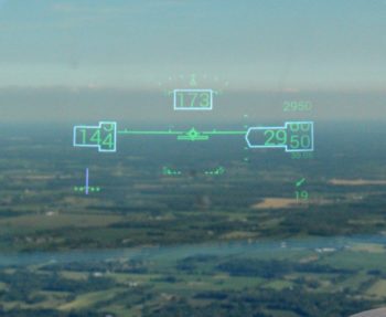
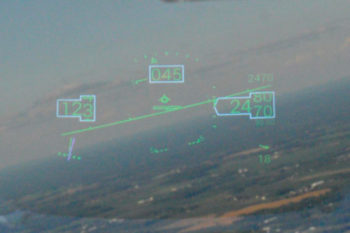
Still being in my self-enforced downtime due to my back and hip (which are getting better at a snail’s pace), I took the time to really dive into this unknown world of GRT HUD technology.  Well, as you can see from the pics below, the integrated HUD along with the GRT avionics does a really good job of displaying a ton of key flight data.

These pics were taken by GRT’s Greg Toman in his RV6 during a bright day.  During Greg’s subsequent discussion on this HUD system he noted that after takeoff on his first flight with the HUD installed, he realized after landing that he had not looked inside the cockpit for primary flight data once during the entire flight.  In short, it was just way too EZ to reference the HUD for this flight data info, which then allowed him to concurrently keep his eyes looking outside for traffic.

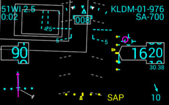
Moreover, GRT’s integrated HUD provides a ton more information than just basic flight data.  In the depiction below, in addition to airspeed, altitude, heading, attitude, altimeter, turn coordinator and wind speed/direction, it also provides

  • HSI (lower left)
  • Waypoint info (upper left): WPT, distance, ETA
  • GRT’s Highway-In-The-Sky (HITS) boxes
  • Armed GRT Synthetic Approach (SAP) [4.5° descent angle, also shown during ILS]
  • Runway depiction (near center of inner HITS box)
  • Flight Director & Flight Path Marker (magenta circle & target symbol above ALT box)
  • Vertical & lateral approach “needles” (yellow hash marks)
  • Runway info/data (upper right): KLDM, Rwy 01, currently 976 feet above runway
  • Selected altitude (upper right) “SA-700”

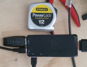
Call me impressed (or a sucker… ha!) but after a 45 minute phone call with Greg at GRT, I was convinced enough to at least give this HUD technology a try.  I ordered a small Android Compute Stick [a mini computer somewhat like the Raspberry Pi, but quite often used for processing video signals] that serves as the BlueTooth interface between the GRT EFIS components and the HUD system.

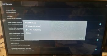
Fast forward to today, where I received the Android Compute Stick and immediately started to get the GRT Remote App loaded onto it (which required an HDMI-cabled monitor, thus allowing me to use my recent space-saving purchase of a Smart TV!). In the end, I was able to cobble together just enough bits n’ pieces to make this happen.  As you can see below, for the pic of the Android Compute Stick I added the ubiquitous decimal tape measure into the shot for size determination.

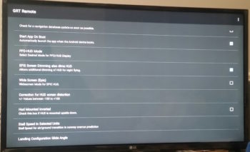
I then set-up the various HUD parameters for what will be my specific HUD configuration.

One nice feature of the GRT Remote App is that it lets you check how the HUD display will look as you change out the various configuration settings in the app menu.

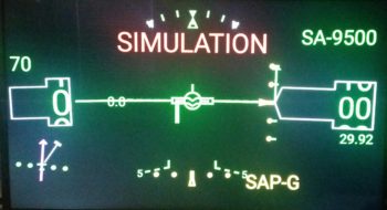
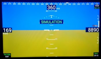
Finally, I do plan on having a small Android screen on a RAM ball mount for GIB situational awareness, so just as an FYI this PFD below is how flight data info will be presented to the GIB.

I don’t plan on actually purchasing the HUD equipment until next year some time, but I did want to get a jump on things for planning purposes HUD-wise.  Thus, I’ve already designated the HUD’s power connection points in my current electrical system configuration.


Chapter 22 – Electrical System Tweaks

My current back ailment puts me in a bit of an irony at the moment: since I want to take it EZ for a good bit to let my back and hip heal up, I am now actually able to do some much needed administrivia and cleanup tasks on the electrical system.  Kind of a catch-22 scenario at the moment in that the longer I delay on getting my house sold, the longer it will take to get back on the build… but in my current state, I’m actually able to focus on a number of aspects of the build.  Life can be weird sometimes!

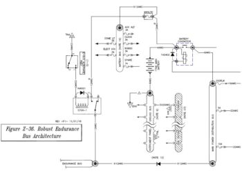
To start off, Bob Nuckolls must be bored (or something!) as he’s been ginning up some new Z diagrams to tweak some of his older stuff.  Well, over a year ago he reviewed my basic electrical system architecture and signed off on it, but in the process told me that I didn’t need a relay that I had in place to control isolating (powering) the E-Bus to SD-8 b/u alternator power when/if I had a main alternator failure.  I removed the relay to simplify and lighten my system, but never had a 100% warm fuzzy on doing so. I also wasn’t keen on my entire E-Bus being powered via a 15A ATC blade fuse off the Battery Bus.  ATC blade fuses tend to be a bit more on the fast-blow side so they are more likely to nuisance trip, so the sizing is a bit more touchy on critical components than say a slower-blow CB.

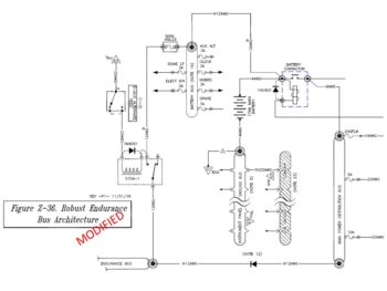
Well, Bob has since remedied both those issues with a new Z-36 design (see below), which I quickly scarfed up and implemented into my system architecture.  Not only does the new Z-36 put the relay back into play, but it feeds the whole E-Bus circuit from a much more robust ANL fuse.  Since I wanted to go with a lower amp rating than 30 amps (depicted on Bob’s diagram), I actually downsized to a MINI ANL fuse and will be using either a 15A or 20A mini ANL fuse. During my research, I was also able to find a good fuse holder mount for it and pulled the trigger on it.

I updated my master electrical system diagram to show this modification, which significantly changed my wiring circuitry to/from the Battery Bus & E-Bus for the b/u alternator power feed, and also the switch circuitry that drives the switching from main to b/u alternator/E-bus power.  Luckily, I hadn’t really wired any of that up so I won’t have to do any major rewiring work. Now, while the logic of my configuration matches Bob’s Z-36, my mechanical implementation is just a tad different than his, as I show here (focus on top center of diagrams):

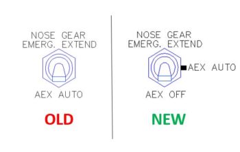
In addition, I spent a bit of time reworking the AEX switch on Marc Zeitlin’s new gear architecture to add an “OFF” position [which, BTW, Marc had in his original design and I am now putting back in based off the advice from Joe Coraggio in his recounting his off-field landing].

My new switch’s wiring is not exactly how I would design it if I were starting from scratch, but it will definitely work and –moreover– will keep the aviation standard of the bottom switch position being “OFF.”  It also eliminates any extensive re-wiring other than lopping off the wires from the current switch and re-soldering them to the new OFF-ON-(ON) switch.  So, on the new 3-position switch, the bottom position is OFF, the middle position is AEX AUTO, and the top momentary position is Emergency Gear Extend, as shown here.

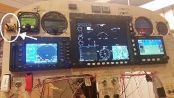
If you’re wondering what switch I’m talking about and it’s location in regards to the panel, I’ve circled it in white and have an arrow pointing to it.  Yes, it’s the one in the black and yellow striped switch guard.

I also took a bit of time while adding the new Z-36 design into my system to do an inventory of all my relays and inline fuses.  I found a couple of discrepancies in the component ID numbers due to repeated additions, changes and swap outs during system design.  I’ve cleaned up the IDs and the lists so I’m up to snuff with both of those electrical system component categories.

My final task related to the wiring was that due to a variety of reasons (from limited behind-panel space to near-max antenna cable run) I decided to place my Trig TT22 transponder out in the right strake pocket and worked up the new wiring scheme for that.  I’m actually running the power wires via the CS spar conduit from the hell hole, so that only leaves 4 x 22AWG signal wires that I’ll need to run through a nylaflow conduit imbedded into the lower front LE of the strake.  While working the wiring for moving the Trig TT22 out from behind the panel to the end of the right strake, I also finalized the configuration for another (2 of 2) consolidated 22AWG 6-wire cable that will start behind the panel and end in the hell hole.

In addition to working my plane’s electrical system taskers, I’ve also been getting back into the books on flying, IFR and avionics.  I’m hoping to get back in the cockpit for another 1-3 months during my transition down to NC to get my flying “sea legs” back underneath me!

Chapter 23 – Engine move to NC

I actually started off this little tale yesterday: 25 October….

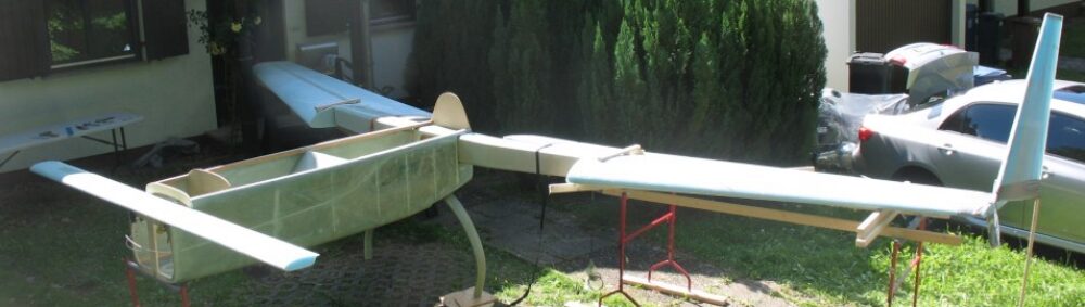
Today I finally got the remaining significant aircraft assemblies for my Long-EZ build hauled down to North Carolina.  The big 3 components that I moved were the engine, the canard and the panel mockup.  In addition, I also moved my glass storage cabinet and cutting table down as well.

The panel mockup, sans the majority of the avionics, simply went into the pax seat of my truck. EZ-PZ.

On the canard, I used 2 of the wood flooring boxes and wrapped each side of the canard, from the mounting tab outboard to the tip.  A tad bit of effort going on there, but still relatively EZ to add some shipping protection to it.

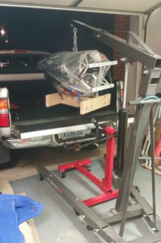
The engine was a different story of course.  Although not overly difficult, it did take a good bit of machination to ensure all would be secure and safe during transport.

My first concern was that since I have the engine pert near full of pickling oil, I couldn’t just simply remove the oil quick drain valve on the bottom of the cold air induction oil sump since it was keeping all the oil where it’s supposed to be!  And since the oil valve protrudes downward a good 3-4″ below the oil sump, it clearly need some nearby supports to keep it protected.

Thus, it was quickly apparent that unlike the thick styrofoam that I had used in hauling the engine home from the shop, I needed a transporting base to keep the bottom of the engine (e.g. the quick oil drain valve) off of the truck bed while in transport.

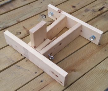
Being a rather clever fellow (ha!), I grabbed a spare 2×6 I had laying around and concocted this thing here.  The 2×6 upright “post” towards the front of this thing is situated along the bottom of the engine case in between and just forward of the alternator and starter, where the case has a little flat spot.  The quick oil drain valve is situated inside the open area made up by the boards running on each side of the vertical post.

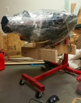
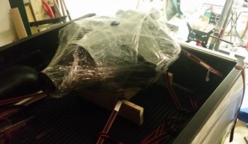
As you can see somewhat, I then strapped my engine transport base to the bottom of the engine using 2 tie-down straps.  I also prepped the engine for a good road trip by encasing what I could in large garbage bags and then wrapping it all with plastic wrap.

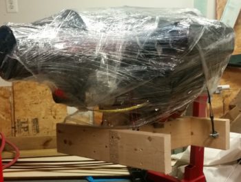
Here’s a more closeup view…

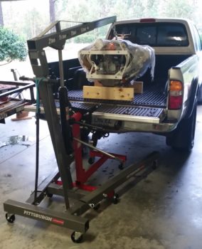
After the 20+ minutes of setting up and configuring the engine hoist, then came the somewhat laborious process of undoing the engine-to-engine stand bolts, then hoisting the free engine –with the attached transport base– into my truck.

I then secured the engine into the bed of my truck.

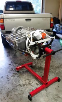
About 15 hours later –after unloading the rest of my stuff into the storage unit– I then got my engine unloaded into my friend’s garage down in NC.  It’s hard to tell in the pic, but there was a steady light rain coming down at this point.

In addition to my engine, I had also hauled down the much required engine hoist and engine stand on the trailer.

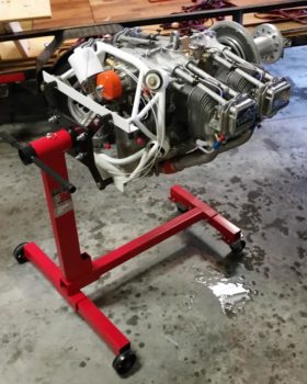
I then simply reversed the process to get the engine back off my truck and onto the engine stand.

And Voila!  Then engine is now safe and sound in NC!

Thus ends another successful mini-adventure in the tale of my airplane build!


Back in black!

Ok, so after a month-long detour my fuselage is back where it’s supposed to be: in North Carolina.  Along with the left wing and motorcycle.

However, before loading the fuselage onto the trailer and departing Virginia for trip #2 down to NC, I decided that I wanted to actually sit in my fuselage and actually look out of the finished canopy for the first time.  I started by peeling the protective plastic wrap back over the canopy to just aft of the roll bar.

Then I climbed in and closed the canopy.

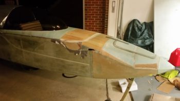
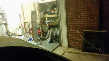
This was the general view I saw looking forward over the nose.

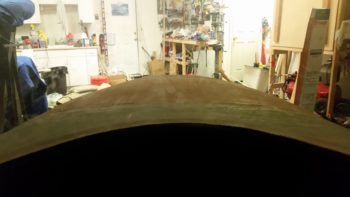
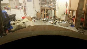
And the view 45° out to the right.  Yes, the bright garage lights were on, but it was night and remember that my canopy is tinted.

I then lowered the nose significantly to check out the nose gear deploy/retract system with me sitting in the fuselage.  Although it sounded like death warmed over, the nose gear actuator did it’s job like a champ both going gear up and then back down.

I then climbed out of the fuselage, replaced the canopy’s protective plastic cover, and loaded the fuselage onto the trailer.

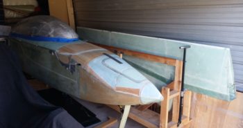
Here’s a shot of fuselage and wing back in it’s proper place: the storage unit in NC.

I still have a few more major build components to bring down, including the canard and the engine, but beyond that I’m calling the build pretty much moved.  On my next trip (in a few weeks) I’ll be bringing those last components down along with my very near to final load out of household goods.  By the end of October my house should be ready –or very close– to put on the market for sale.