Chapter 14/23 – Engine Mount Extrusions

Today I started off by cutting the upper left 4130 steel engine mount extrusion into 8″ & 1.6″ lengths.

Cutting upper left engine mount extrusion

Cutting upper left engine mount extrusion

I then trimmed the lower 0.1″ reinforcement plate for a final fit to the upper left engine mount extrusion pieces.

Left reinforcement plate trimmed

I then drilled the countersunk screw holes in the upper left extrusion mount pieces.

Drilling holes in upper left extrusion

Here’s a shot of the 3/16″ countersunk screws mounted in the upper left extrusion mount pieces.

Mounting lower reinforcement plate

And all three 3/16″ countersunk screws mounted in the upper left extrusion mount pieces.

Lower reinforcement plate mounted

I then drilled the countersunk screw holes in the upper right extrusion mount pieces.

Mounting lower reinforcement plate

Here’s a shot of all three 3/16″ countersunk screws mounted in the upper right extrusion mount pieces.

Lower reinforcement plate mounted

Below are the 3/16″ countersunk screws & lower reinforcement plates in place on the upper extrusion mount pieces.

Lower reinforcement plates mounted

I then mocked up the CS105 control tube & test fitted it in place in the CS109 mount. With the CS105 tube moved inboard, the hole through the front seat will have to be widened just a hair in the area I’m pointing out with scribe in the pic below.

CS105 control tube mounted

CS105 control tube mounted

And did the same on the aft side with the CS105 control tube test fitted in place in CS118.

CS105 control tube mounted

CS105 control tube mounted

Here’s a shot of the CS105 control tube test fitted in place in both the CS109 & CS118 control mounts.

CS105 control tube mounted

I then set the right side pilot arm rest in place, with the CS105 control tube test fitted in place.

CS109, CS105 & armrest

CS109, CS105 & armrest

I then did the same with the GIB armrest, with the CS105 control tube test fitted in place. Thankfully, the fit on both forward and aft right armrests are fine.

GIB right armrest

Tomorrow I plan to work on the aft left arm rest and then start back on the final canard & elevator install.


Chapter 16 – CS109 & CS118 final install

Today I started out by laying up the 1-ply of BID on the forward side of CS109 that I had intended to yesterday, but needed to go with smaller corner layups in order to have CS109 taped in place to the right arm rest so that it would be positioned correctly.

Normally I would glass the aft side of CS109, but after reviewing the plans, and since I do have a small corner piece of BID on the aft side, I’m going to leave it until I glass the arm rest in place (yes, I am in the current minority of builders that still plans on glassing my armrests into place & not make them removable).

[Note: I cleaned up this layup a bit more after this pic . . . in case you’re wondering (smile)]

Glassing forward side CS109

I then sanded the cured BID on the aft control mounting bulkhead, CS118, and then redrilled the #12 holes.  CS118 is complete.

CS118 sanded & holes re-drilled

I then spent almost 2 hours cutting all the BID required to install the top & bottom engine mount extrusions (4 total) to the CS spar & longerons.  Probably not a very exciting pic… but cutting glass for nearly 2 hours isn’t exciting either!  ha!

BID for engine mount extrusions

Although towards the bottom of my task list today, I finally got sick of looking at all the peel ply boogers on the CS spar-to-fuselage layups, so I gave it a higher priority!  You may have noticed in my blog post yesterday the significant amount of dust & debri in the nose from mounting the canard (which is now gone…the debri, not the canard!)… with all that was going on I simply didn’t have enough time before heading out to Rough River for a good after action cleanup, and am just now getting around to it.  I spent well over an hour cleaning up all the layups from mounting the CS spar to the fuselage, and also the inboard holes in the CS spar forward face I filled with foam & glassed. If you remember, I made those holes for drilling the wing bolt holes.  I still need another good hour in ridding the spar (and then later the wings) of all the offending bondo.

CS spar to fuselage layups cleaned up

After cleaning up the aft side of the fuselage, I then pulled the peel ply and knife trimmed the CS109 front side layup.

CS109 peel ply pulled & knife trimmed

Again, I’m going to wait to glass the aft side CS109 until I install the right arm rest. Tomorrow I’ll sand this mount down and redrill the #12 holes.

Will glass aft CS109 when arm rest installed

Well, tonight was finally the night!  I spent about 3 hours reorganizing, cleaning and straightening up the shop.  This is just phase I and I plan on knocking out phase II tomorrow.

Shop cleanup & reorg

The main thing I’m happy about is that I can walk to the front of the shop to back of the shop without having to low crawl under my CS spar.  Just 2′ to one side of the spar to pass, and I am one happy camper!

Shop cleanup & reorg

I don’t have a shot of it, but the final act of the evening was that I spent a good 30-45 minutes filing down & cleaning up the edges of the upper left 4130 engine mount extrusion. After another 15-20 minutes tomorrow, it will be ready to be cut to its final 8″ & 1.6″ lengths.


Chapter 16 – CS109 & CS118 control mounts

I started off today acting upon some information that I got from my buddy Dave Berenholtz down in OZ.  He said that his Long-EZ was built in 1987 and that over the years the requisite plan’s holes in the bottom of the Instrument Panel –with the foam exposed to air, etc.– have  deteriorated significantly from the edge of the foam not being treated.  This jived with what my Instructor from the EAA Composites Workshop stated when he said that builders should always cover exposed foam with either micro or flox.

So today, before I got started on re-installing the CS109 & CS118 control mounts, I decided I would get the lion’s share of this task knocked out.  I figured that if I channeled the foam in the lower Instrument Panel holes before I started any glassing, then I would use whatever leftover epoxy I had at each step to use for micro to edge these holes.

Foam edges on lower panel holes

After I used the Dremel tool to remove a small channel of foam around each of the Instrument Panel’s lower holes, I then cleaned up the dead glass from the previous install of CS109.

CS109 site & lower panel holes prepped

I then did the same thing in the back seat, and cleaned up the existing glass from the previous CS118 install.

CS118 site prepped for glass

I cut 4 plies of BID on the table (not shown), one for each side of the respective control mounts, and then set about to drill the #12 holes through CS109.

Drilling #12 holes in CS109Drilling #12 holes in CS109

Here’s a shot of the AN3 bolts test fit.

#12 bolt holes drilled in CS109#12 bolt holes drilled in CS109

I then did the same thing for the aft-side CS118 and test fitted those AN3 bolts as well.

#12 bolt holes drilled in CS118#12 bolt holes drilled in CS118

To ensure I could remove the arm rests after the 5 min glue stuck CS109 & CS118 to the fuselage sidewall, I covered the top inside armrests with clear packing tape.

Right armrest underside taped

I then 5 min glued CS109 in place to the fuselage sidewall, while taping it in place with duct tape to ensure it aligned properly.

CS109 5-min glued in place

Of course I did the same thing in the back for CS118.

CS118 5-min glued in place

The forward CS109 control mount wasn’t as solidly stuck in place with the 5 min glue, so I went ahead and worked the back CS118 mount first.   Below you can see that the 5 min glue did its job and kept CS118 right in place.

CS118 5-min glue cured

I whipped up some MGS285 epoxy with fast hardener, and then some flox, and added flox fillets in the corners.

Flox fillets on CS118

I then laid up 1 ply of BID on each side of CS118 and peel plied the layups.

CS118 glassed 1-ply BID each side

CS118 glassed 1-ply BID each side

Since I still needed the tape on the front side to secure CS109 in place, I simply laid up 1 ply of BID on each side, but kept each ply small at 2″ x 2″… just enough to lock in the position of the CS109 control mount & keep it aligned properly with the arm rest.  I then peel plied the layups [Note the micro in the foam edges of the lower instrument panel holes].

CS109 in place while BID cures

While the CS109 & CS118 layups were curing, I then drilled a #12 hole down into the upper left engine mount extrusion’s bottom reinforcement plate.  I then countersunk the hole in the outboard 2024 aluminum angle “L” bracket.  I didn’t want to drill the other 2 holes on the other side since I wasn’t sure how much compression there would be when the engine mount was actually bolted in place (the plans say 4 AN3 screws according to a CP… but I seriously don’t know where 4 holes would fit for AN3 screws.  There technically is 4 screws/bolts going through the extrusion plates into the lower reinforcement plate, IF you count the 1/4″ bolt that holds on the engine mount tube).

I did realize after I Alodined these parts (below) that I had a major brain SNAFU and should have at least drilled & countersunk the screws on the top (long) extrusion.  I could then have simply drilled the holes into the lower reinforcement plate later, since it connects both sides… oh, well.  No huge deal, just definitely not optimized as for as Alodine coverage.

Drilling outboard engine mount tab

Now, my main Alodine goal for today was to at least get the Engine Mount Extrusions Alodined.  I cleaned all the parts with a quick wipe down of Acetone.  Then I cleaned them with a 3M pad and Simple Green, and rinsed them thoroughly.  I then took them outside and Alodined them.  In addition, I was also actually able to prep & Alodine the Aluminum parts for the wing bolt brackets that will allow me to mount the wing bolts in the spar quasi-permanently facing aft to greatly simplify wing mounting/removal.

Extrusions ready for Alodine

After I was done Alodining all the aluminum parts & letting them dry, I pulled the peel ply off the CS118 layups & razor cut the BID glass.

CS118 peel ply pulled & razor trimmed

Here’s a shot of the new & improved CS118 glassed into place.  Tomorrow I’ll finish sanding the edges & redrilling the bolt holes.

CS118 glassed & looking good!

The CS109 mount initial attachment layup came out fine as well.  I didn’t realize that I had floxed in such robust fillets, so that sucker will definitely be strong!  Tomorrow I’ll add another full ply of BID to the front and aft side.

CS109 ready for BID ply each side"Robust" flox fillets on CS109! ;)

I quickly double-checked the fit & alignment with the front right arm rest, and it fit great!

CS109 position is good!

Here’s the last shot of the evening (not, however, the last action of the evening since my hose sprung multiple leaks as I was Alodining this stuff, and my shop still needs some TLC to get some water out from underneath some stuff!!!)

You can see below that the 3 aluminum engine mounts and the outboard spar wing bolt brackets are Alodined.  Clearly I still need to finalize cleaning up the edges of the 4130 steel engine mount.

Alodined engine extrusions & wing bolt brackets

Now that I have a good bit of these of smaller tasks out of the way, I really do plan on attempting to reorg the shop tomorrow in order to get it prepped for finalizing the canard & elevators install!


Chapter 14 – Engine Mount Extrusions

Actually, engine mount extrusions were just one small part of today’s activities . . .

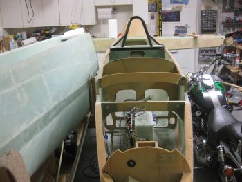
My goal today really was to get the new CS109 & CS118 plywood bulkheads cut and glassed back in place in the fuselage.  Uh, this didn’t happen.  Although I did get a lot done.  My secondary goal was as I got something curing (CS109 & CS118), I would then get the shop reorganized so I could build something, let alone just move around.

Let’s just say that there was a lot of “drag” today in that instead of things taking 1 or 2 steps, the prerequisite tasks of just getting materials out of the shop closet, or finding tools, took much more time than it should have.

After I marked out the dimensions of CS109 & CS118, I then pulled out a scrap piece of the 1/4″ Finnish Birch plywood that is used for the firewall.  Since I had no other scrap plywood pieces big enough for either plywood bulkhead, I had to get into the closet, which was a feat unto itself!  ha!

Scrap Birch plywood for new CS109/118

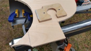
I found some good spots to cut out the new plywood bulkheads, marked them up & then cut them.

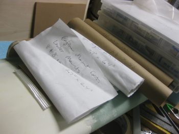
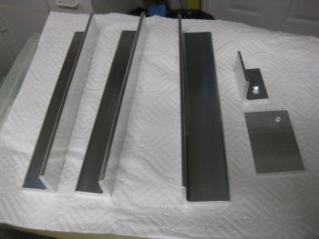
[I should state that this was not my first foray into cutting wood today.  I actually started by cutting the four (4) WA16 Spruce wedges for mounting the engine mount extrusions to the spar & longerons.  One of them needs to be a bit taller, so I will be re-cutting one more.  They are in a rough stage now & still need to be sanded. Sorry, the only pic I have of them currently is at the end of this post.]

Re-cutting CS109

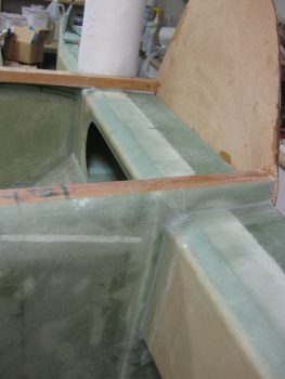
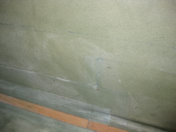
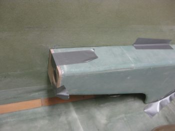
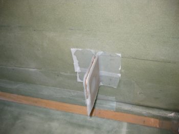
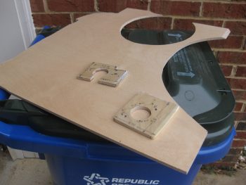
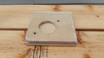
Here’s a shot of the new CS109 plywood blank.

CS109 Birch ply blank re-cut

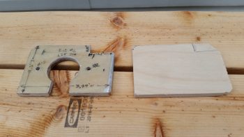
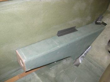
And the same for CS118.

CS118 Birch ply blank re-cut

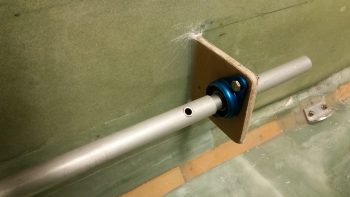
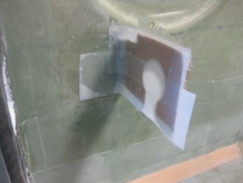
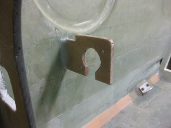
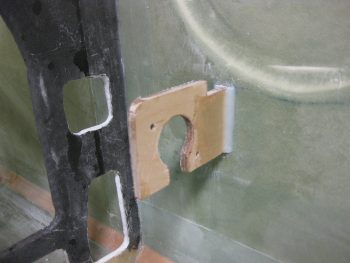
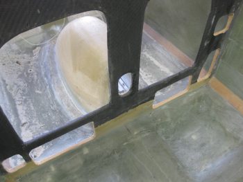
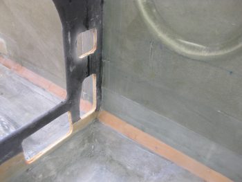
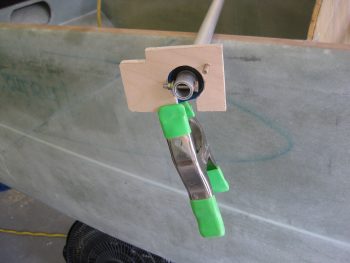
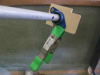
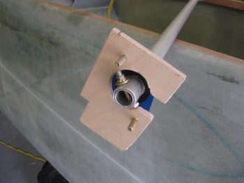
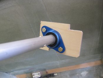
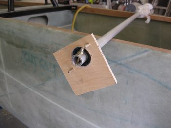
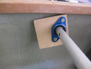
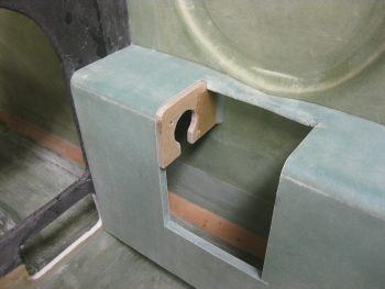
As a reminder, the reason why I’m redoing the CS109 & CS118 control stick mount bulkheads is due to the fact that the Cozy Girrrls sell the Cozy style stick mounts (I’m guessing….) for the Long-EZ.  In the pic below, which I shamelessly stole from my buddy Dave Berenholtz’s site, you can see that the CG stick mounts straddle the CS105 control tube, whereas in the original Long-EZ the control stick merely bolted to the inside the CS105.  If this lost 3/4″ offset to the inboard side of CS105 isn’t accounted for, then clearing the side wall either top or bottom of the stick will be problematic.  Interestingly, and as I told Dave in an email, since I widened my fuselage and my armrests just a hair bigger, I had already kicked the holes in CS109 & CS118 inboard by 0.4″.  I might have actually been able to get away with doing nothing, but it was good that I took these off. The good part is that I only had to move the holes another 0.35″ inboard.

Cozy Girrrl Control Sticks

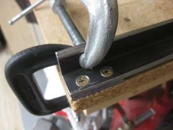
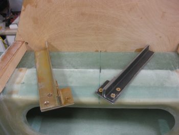
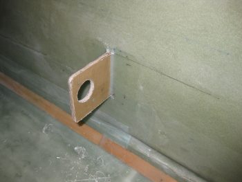
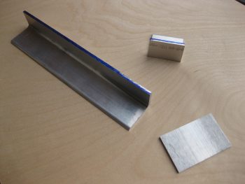
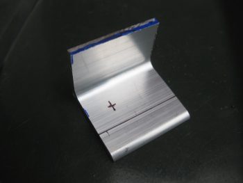
I then cut the 1/8″ thick 2024 aluminum bottom engine mount extrusion support plate.  My upper Right side extrusion originally had 1.5″ x 1.5″ legs, but since I didn’t want the top vertical leg extending so far up above the longeron, I trimmed it down to 1.25″.  The horizontal leg I left at 1.5″ on the INBOARD side.  I planned to trim down the OUTBOARD 1.6″ long extrusion to 1″ wide (see below).  Thus, I needed the bottom support bracket to measure 1.6″ long  x 2.5″ wide.

1/8" bottom 2024 extrusion plate cut

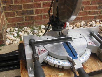
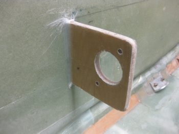
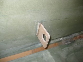
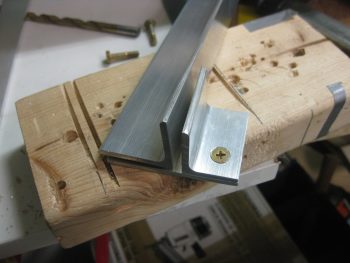
To trim the OUTBOARD 2024 upper right engine mount extrusion to 1″ wide, I needed to secure it so that the miter saw wouldn’t chew it up.  I knew it needed at least one bolt hole in the bottom leg of the plate, so I marked a spot for a #10 hole.  As you can see, I marked the 1″ cut line as well.

Trim 1.6" extrusion to 1" wide

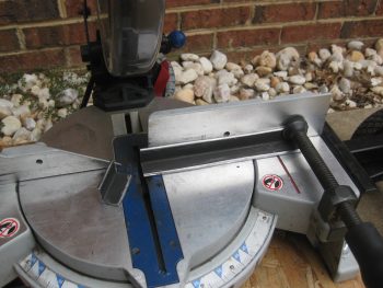
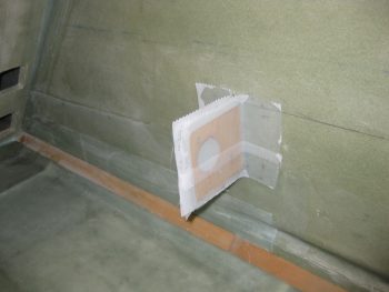
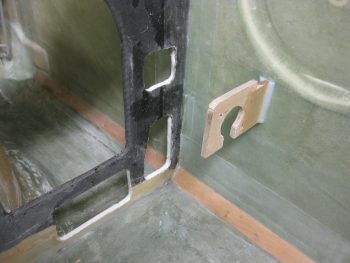
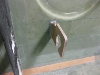
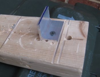
I then drilled the #10 hole and mounted the extrusion piece to a scrap piece of wood.

Trim 1.6" extrusion to 1" wide

I then cut the extrusion down to 1″ wide on my miter saw.

1.6" extrusion cut to 1" wide

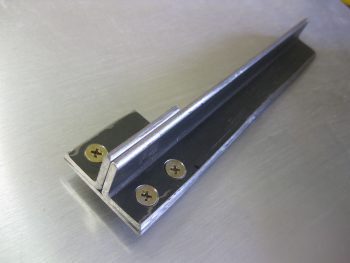
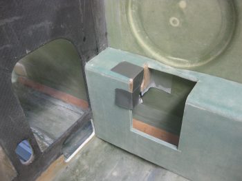
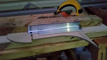
I then made up a quick jig that made it so that a 2×4 was the same height as the 1.25″ high 2024 engine mount extrusion.

2024 extrusion jigged for router

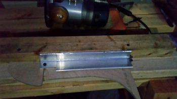
I then took my router with a 1/8″ roundover bit and radiused the edge of both short & long engine mount extrusions.  Again, these are still in the rough stage and I have to finish cleaning them up.

Radiused 2024 extrusion top edge

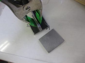
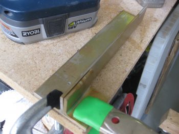
I then cut the 0.1″ thick 4130 steel bottom engine mount extrusion support plate for the upper left engine mount.  I didn’t have any 1/8″ thick 4130, and honestly didn’t order any because 4130 is some amazingly strong stuff, so 0.1″ will do the trick…. and with slightly less weight.

I cut the first cut using another chop saw I have with a metal cutting blade on it.

0.1" thick 4130 bottom extrusion plate

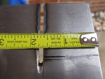
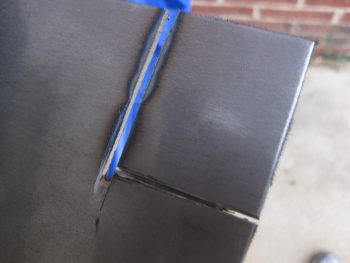
For the 90° cut I simply pulled out the Dremel tool and used it.

Dremel tool for final cut

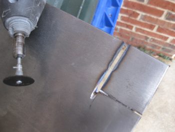
It only took a few minutes to cut through this steel.

Dremel tool for final cut

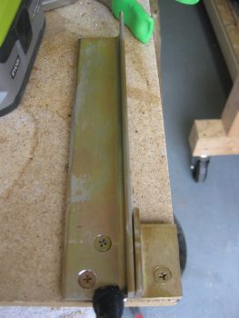
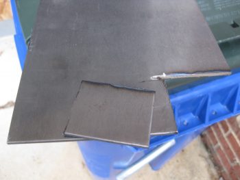
And voila!  The bottom 4130 support plate for the engine mount extrusion on the upper left side.

0.1" thick 4130 bottom extrusion plate

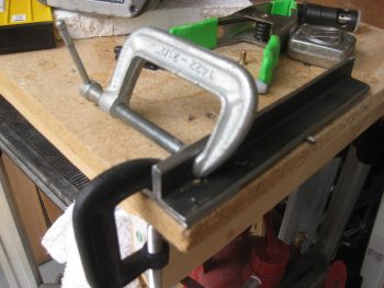
Since I had the saw out, I grabbed a small aluminum hinge that I had set aside a few weeks ago for the battery compartment mounted tool box.  I then cut a hinge for the tool box.

Tool box hinge cut

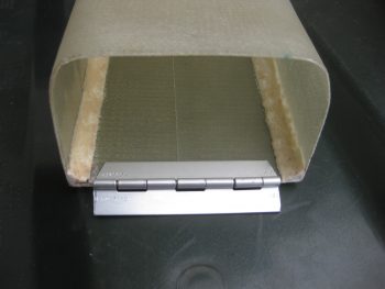
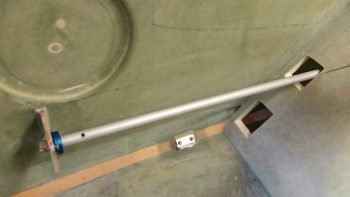
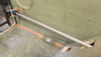
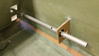
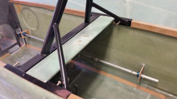
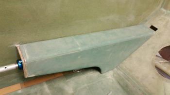
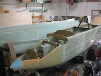
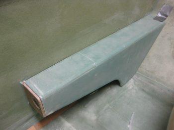
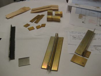
Below is a shot of todays machinations.  In addition to the tool box hinge above, I also trimmed the GIB handle tube to length (6″, at least for now) & cleaned it up.  BTW, it weighed in at a whopping 0.086 lbs, and that’s with the grip in place.

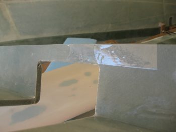
Yet another bunch of material I cut but didn’t get any pics of are the pieces that will make up the U-channel wing bolt securing bracket (in the middle of the pic below).  This will allow me to put the wing bolts in the spar facing out (aft) and be secured against moving.  This will greatly facilitate the speed & ease of putting the wings on & off.

A day's worth of work!

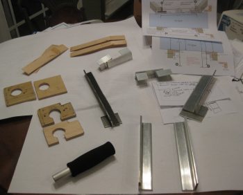
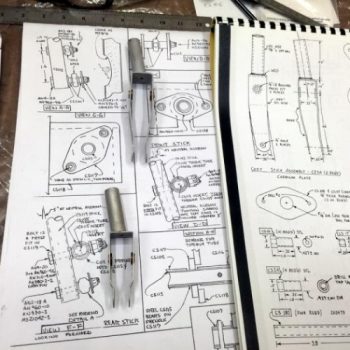
You may also note that in the pic above I included printouts of my engine mount extrusion diagrams/notes that I updated yesterday.

I may get an hour or two in tomorrow evening, but basically I won’t be full on in the shop again until Monday.  Pretty much all the parts I cut today need to be sanded, shaped, deburred, etc.  I then really need to get the shop reorganized after I get all these smaller bits ‘n pieces squared away.