Chapter 22 – Play Time is Over!

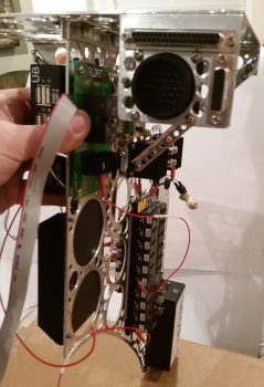
No more electrical stuff for me… back to the GIB area!  Ok, except this one sideline task. HA!

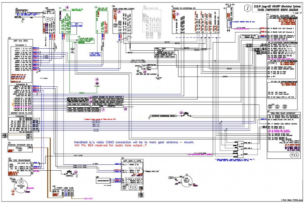
Today I started by finishing up annotating the J3 PQD connector color codes, which of course meant digging in the GRT Mini-X manual and also seeing what the wire colors were that I physically had on hand.  Since I had the Mini-X wiring harness (15-pin D-Sub) in my hand, I decided to go ahead and knock out the wire harness connector for my Mini-X.

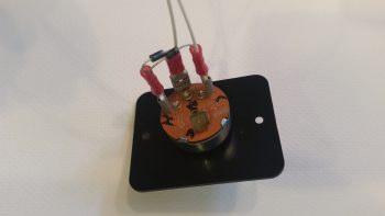
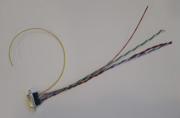
First, I had to pull a few wires for connections that I won’t be using.  These few specific wires came installed on the GRT-provided 15-pin D-Sub connector/harness.  I measured the required wire lengths between the back of the Mini-X and the J3 PQD connector on the Triparagon.  I added a couple of inches for ‘insurance’ purposes and another half inch to account for the multiples pairs that would be twisted together, then ended up cutting all the wires down to 10.5″ long.  I then crimped some D-Sub sockets onto 3 wires for the magnetometer (since it’s optional) and terminated them into the Mini-X D-Sub connector.  I then twisted the appropriate wire pairs together using a small portable drill.

I then terminated the ends of the wires with D-Sub pins on the opposite end from the Mini-X connector and performed a continuity check on each wire… all good.

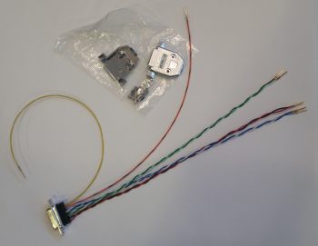
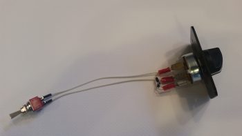
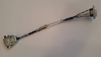
Then, on the Mini-X side of the harness I installed the D-Sub backshell.

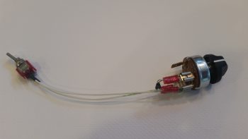
Having also just received some more correct-sized wire labels, I then labeled the 2 individual wires and the 3 wire pairs.

For the panel component labels that run ONLY between the panel components themselves, or the panel components and the PQD connectors, I’m using a bit more simplified wiring label scheme than the one I use for the rest of the plane: essentially providing just a pin number, the wire function such as “power” or “DU link” and an opposite pin number, all separated by dashes.  Obviously, on the panel I’m looking at the wire runs from the back of the given device and seeing its termination point just a scant few inches away… all the info is there for me to see straightway, except the pin #’s and wire functions. So, for example, the lone magnetometer signal wire label goes like this:

10-MAG SIG-9

Pin 10 on the Mini-X EFIS D-Sub connector, the truncated description as to the function of the wire, and Pin 9 on the J3B PQD D-Sub connector.  Short and sweet.  If a twisted pair is getting labeled, I simply add both pins on each side separated by a “/” (aka 11/12).  I’m still sticking with the more robust label scheme throughout the rest of the plane which allows me to determine where the wire is coming & going, what devices it goes to (points A & B) and what pins it connects to at each end (typically power, ground or data signal).

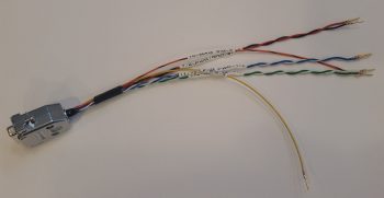
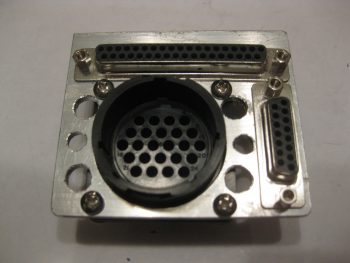
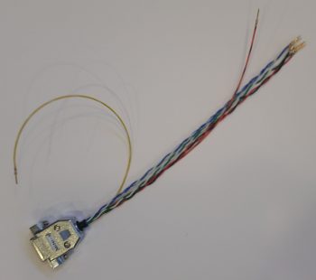
Here’s a shot of the Mini-X wiring harness, minus the D-Sub 15 backshell (which is on order) for the J3B side.

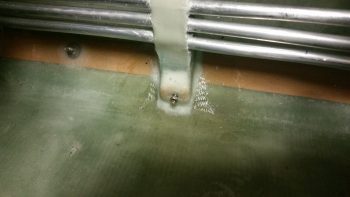
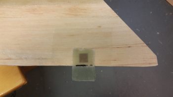
I then set my sights on finalizing the GIB right side kick plate mounting.  I started by stuffing some plastic saran wrap into the aft lower hardpoint screw hole, and then laid up a ply of BID over it.

A few hours later it was really close to being cured, so I hand drilled the hole through the glass in the front to remove the plastic.  I then cleaned up around the hard point screw hole and test fitted the screw.

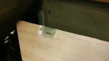
Here’s another wider angle shot of above.

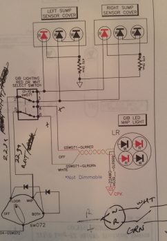
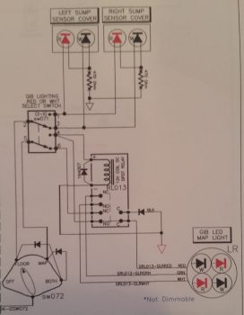
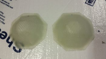
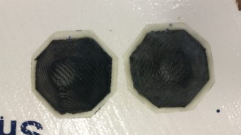
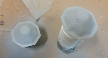
I then spent a bit of time sanding down and cleaning the fuel sump low fuel sensor covers.

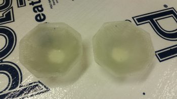
Here’s the exterior side of these things . . .  After sanding, I then gave them a good Simple Green wash and dried them off.

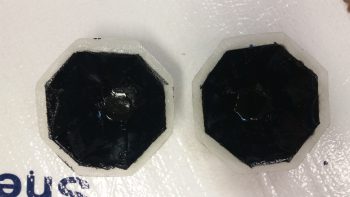
I then taped up the interior edge of both sensor covers and then shot them with a couple quick, light layers of black paint.  I would have preferred to use matt paint, but I only had gloss on hand so they’re a bit fancier than I had intended.

I then prepped both the outboard side fuselage area and of the interior wall of the kick plate with clear packing tape to keep the composite bracket from gumming anything up.

I then set up 2 prepregged 3-ply BID layups.

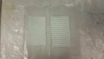
I then wet out the prepregs and combined the 2 stacks of 3 plies to make up a 6-ply forward kick plate mounting bracket.

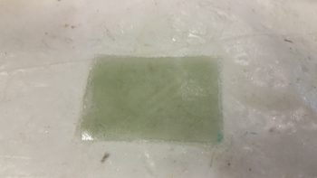
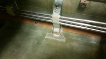
I then laid up the 6-ply bracket layup half way onto the forward kick plate mounting hardpoint.

I then folded it back on itself so that it was almost touching.  My goal here was that when the kick plate was mounted, gravity would simply pull the glass down onto the protective tape on the floor, creating the exact correctly shaped bracket blank –since the floor at the corner here is 45°– after it cures.

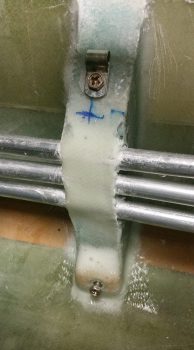
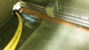
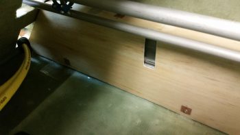
Here’s a shot of the entire kick plate, with the 6-ply mounting bracket glass formed on the inside.  I was able to get just a peak of it through the holes in the front seat bulkhead and from what I could ascertain, my “shot in the dark” layup looks ok.

As the kick plate bracket glass cured, I then took a quick opportunity to apply a couple of coats of gray primer onto both thigh support fuel sump low fuel sensor covers.  Since I’ll have a pair of LEDs poking out the bottom of each of these covers, I wanted to get them painted so as to not have to worry as much about taping off those LEDs, which again will be on the bottom side, when I paint the rest of the back seat area.

Tomorrow I’ll continue working on all things GIB!


Chapter 22 – Uh, more electrons please!

Well, I’ll be darned if another task didn’t blow up into a huge project.  I had planned on using this morning to finalize the electrical stuff I did yesterday: print out the diagrams and connector pinout sheets and verify a few connections.

I did just that and then, although electrical in nature, got back to working on the GIB area by working on the circuit for the GIB cabin lighting.

My GIB area cabin lighting essentially consists of 2 zones:

  1. The upper zone lit by a red/white LED map light.
  2. The lower zone lit by red/white LEDs mounted in the sump low fuel sensor covers.

I decided to start on the switch side which consists of a mini-toggle that allows for selecting all GIB area lights to be lit either RED or WHITE.  This then connects to a rotary switch that allows the GIB to determine which lights are on or off with the following positions:

OFF – FLOOR – MAP – BOTH

So I got both switches configured & initially wired up, and all was fine until I had to tie in the LED map light.

As you can see the map light has 3 wires: white, red, and green.  I mistakenly assumed that the separate, selectable red and white set of LED lights were powered by the red wire for the red lights and the white wire for the white lights, with the green wire (maybe I’ve spent too much time installing house light fixtures!) being the ground wire.

Which is exactly how I had it drawn up for years!

But, alas, the manufacturers of these map lights pulled a switcharoo and pretty much made the install specific to powering the lights through an ON-OFF-ON switch with each light being controlled by closing that color (red or white) circuit to ground with the switch. You can see an initial swag I took at this in the lower right corner in the pic above… albeit I lopped off the ground symbols when I cropped the pic.

I played around with it for a while, getting a bit pissy having to “waste” time on a small luxury item as this GIB map light.  Moreover, all day my Chi was apparently way off center because I was letting a ton of that critical electrical smoke that must be contained out of as sundry items such as relays, diodes, wires . . . you name it! I clearly had the reverse midas touch so when I was done creating smoke by incidental shorting of wires, etc. I decided to dare not touch the plane nor attempt any glassing later in the evening!

Although I did –after much effort, angst, creative use of expletives, persistence and hard thinking (which was like pushing a brick wall!)– finally tested out a good circuit for the GIB LED lights, which took a few hours and involved incorporating a spare small DPDT relay I had on hand (don’t ask how long it took me to find it!).  BUILDERS HINT: Install the diode in the circuit the correct way!!  Ask me how I know . . .

The challenge was that I already had the entire circuit designed and mostly constructed, so I was adding on to the tail end of it and couldn’t really pick my power & ground wires from scratch (without adding more long wire runs or even more complexity).  I eventually got it, and thus I present to you the new GIB LED lighting circuit:

Yes, hopefully tomorrow I can actually get back to the REAL GIB area tasks!


Chapter 22 – Electric all the way!

Well, as not that uncommon in this build, what was supposed to take a few hours ended up taking up every minute of my day today and propelled itself into the wee hours of the morning.

But my immediate task is done . . .  for now of course!  I tried a few different ways to get this on the screen, but alas my JPG captures on my CAD program suck.  So I just took a screen shot (pic below).  It gives you a general idea of what I was up to all day yesterday sorting through essentially a massive pile of spilled spaghetti.

I pretty much assessed every wire and every connection coming out of the GRT HXr EFIS (PFD), GRT Mini-X EFIS (MFD), Garmin GNS480 GPS receiver, and Trio Pro Pilot Autopilot. I identified if the wires would simply be run from point A to point B, or in a twisted pair or shielded conduit, all based on the requirements coming out of the installation manuals or the manufacturer’s guidance.  Where there was no specific guidance I turned to words of wisdom from the grand pupa of aircraft electrons, Bob Nuckolls, by referencing his masterpiece, The AeroElectric Connection.

In addition I clarified some info via phone calls and emails as I did with Chuck from Trio Avionics.  And will do the same with GRT tomorrow.

As I mentioned yesterday, I also labeled every RS232 serial pair and ARINC 429 pair for the data signal wires with their respective configuration labels and correlating baud rates that will be used when setting up the individual components to talk nicely amongst themselves.  I was also able to reallocate and free up some serial ports based on my newfound knowledge and tweaking of my system (also facilitated by some updated manuals such as a new 2017 install manual for the Mini-X).  This, in turn, both reduced the physical number of wires and allowed me to clear off unneeded ports that I was tracking on the diagram above.

With the wire types identified for each port, I was then able to massively rework my Panel Quick Disconnect (PQD) connectors and consolidate all the HXr EFIS harness wires on the J4 PQD 37-pin D-Sub connector.  I was just short a couple of positions, so I moved the power off the J4 connector and repurposed the J10 connector label for a new 4-pin mini-Molex power connector (HXr primary, secondary and tertiary power plus ground).  The old J10 connector got bumped down the line and is now J12.

Below is a page out of my connector pinout tracking sheets packet.  I track literally every wire, pin & socket in every connector on this aircraft.  As you can imagine, I’m waiting for the day when I can stop updating these sheets!

In addition, I did exactly the same thing in consolidating every wire for the Mini-X through the J3 PQD 15-pin D-Sub connector.  This is very significant in that it allows me to simply unplug & remove my HXr EFIS by disconnecting only 2 connectors: a D-Sub & mini-Molex (ok, and a USB cable . . . you got me!).  Moreover, If I choose to, I’ll be able to disconnect & remove my Mini-X EFIS by disconnecting 5 things: a D-Sub, a USB cable, the GPS antenna cable, and of course the Pitot & Static connections.

After I finished reworking my panel component wiring diagram and the pinouts for the 3 PQD connectors, I then did a scrub of every wiring diagram I have on hand, which is nearly 30 diagrams.  In addition to the panel component wiring diagram, I had to do significant updates to 8 other diagrams.

To help bring all this massive paperwork drill to life so you can see it in the physical world, I went back and snagged a couple shots of the Panel Quick Disconnect (PQD) connectors in the PQD bracket (still in its rough state before cleanup) so you can see what I’m talking about.  The 37-pin D-Sub J4 HXr connector runs across the top, while the 15-pin D-Sub J3 Mini-X connector runs down the right side.  The big round 24-pin connector, which admittedly is sparsely populated now (read: scalability) is the P6 AMP CPC connector.

Here’s a shot of the PQD connector bracket at the aft right corner of the Triparagon’s top cross shelf.  The PQD bracket is situated right below the aft face of the Trig 22 Transponder.  In addition, the PQD connectors are only a scant 4.5″ (IRRC) from the aft side of the HXr and Mini-X . . . so close in fact that I could not physically install the cable clamp on the aft panel-side P6 AMP CPC connector and still have clearance to run all the wires!

With my short deviation back into the world of electrons over (…for now!), I can get back to tackling the GIB area and start seriously planning on knocking out the nose and canopy (with perhaps a quick sideline tryst to finish the wheel pants?!)

Chapter 22 – Panel Cross Connects

Well, I’m back from my nearly weeklong trip down to the North Carolina coast and Virginia Beach.  This past Thursday Marco flew down to New Bern, NC and picked me up and flew me back to his EZ’s home base at Chesapeake.  At 45 minutes airport to airport and averaging just over 6 gallons of fuel an hour, you can bet I’m motivated more than ever to finish my Long-EZ!

Spending a few days with Marco and Gina was great of course.  Since Marco is actually interconnecting all his panel upgrade components (GRT EFISs, Garmin GNS480 GPS, etc), it gave me a lot more insight on the configuration settings required to get all these panel components to talk to each other.

With all this configuration settings stuff fresh in my mind, when I returned home on Saturday I spent about 3 hours digging into the manuals to facilitate adding port speeds, port labels and IDs to my wiring diagram interconnect wires for my PFD, MFD, GNS480, Trio AP, transponder, etc.  With a deeper understanding of the ARINC connections, this process also allowed me to further find a couple of design configuration questions that I need to get some answers to.  So I fired off an email to Chuck at Trio to get some of those answers.

I continued my digression (or distraction!?) yesterday as I got close to wrapping up my panel wiring diagram by ID’ing specific wiring types (twisted pair, shielded, standard) for each cross connect.  I also created a spreadsheet that IDs all the major programming configs for my separate panel avionics/instruments.  I’ve already configured the majority of settings –as far as I can currently– on both my Garmin GNS480 GPS receiver and my GRT Mini-X EFIS.

Tomorrow I’ll start off by rewickering my Panel Quick Disconnect (PQD) D-Sub pinouts to allow both GRT EFISs –PFD & MFD– to be quickly disconnected when I remove the panel.  So, a minor rabbit hole, but I think it will be good to get the avionic/instrument components’ configurations tweaked while it’s all still clear in my mind.  I’ll also continue my electronics quest by testing out my GIB lighting circuit and then try to get those into place inside the covers that get installed over the GIB thigh support sump low fuel sensors.  Not only will that be another major GIB area install out of the way and confirm some proposed circuitry, but will be another electrical install task completed.