Chapter 23 – Cowls: Closing In

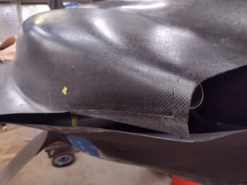
I started off this morning by pulling the peel ply from the “3-ply” CF layup on the bottom aft edge of the top cowling.

I called it a 3-ply layup to make it simple in my last post, but actually only the front half of this layup, about where the sharp trailing edge terminates near the middle, has 3 full plies of CF.  From that point aft there is only one ply that is fairly narrow, borders the grey tape and terminates at nearly a point at the aft end of the cowling.  This is due to the narrow CF piece I added being fairly thin.  That being said, there is room for one more ply to fill this remaining lower area at the aft end of the cowling.

Again, this isn’t my preferred style of cowling closeout, but I realize that A) there has to be space allowed for the exhaust pipes —and that is THE reason you have this bulbous lower cowling meeting up with the top cowling TE; and B) not only is this how Mike Melvill designed it, but going with the design seemed to be the best path of least resistance in getting these cowling installs finished.  With that being said, I’ll remind everyone that this is an iterative process… mainly because I’m not only constructing the lower lip of the top cowling, but matching edge thicknesses between top and bottom cowlings as well.

I then prepped the surface on the right bottom side of the top cowling.  I cut another filler piece of Lantor Soric and applied it in about the same area as on the left side. I also had a narrow (less than 1/2″) one-ply CF filler piece for the dip at the seam of the aft and middle flange layups.

With all the prerequisite tasks out of the way, I laid up 3 plies of CF butting up to the edge of the bottom cowling on the lower side (gray tape) and along the top cowling TE on the front half and the top cowl original edge on the aft half.

I then peel plied the layup.  I’ll note that I used MGS 285 epoxy on this layup.

I already had a loose plan of how to layup the final plies of CF on the left bottom side of the top cowl, but that was accelerated a bit since I had some MGS 285 leftover in the cup from the right side (par usual… sigh).

My first ply on was what I discussed above, a very narrow wedge shape at the aft 8″ of the cowl, butting up against the gray tape edge and filling the area that only got one ply on the first go around.  I then added a ply that butted up against the aft end of the bump created by the embedded Lantor Soric piece.  This ply also butted up against the gray tape seam but was about 1/2″ shy of the sharp TE, wrapping around & upward just aft of where the TE dives into the vertical wall of the top cowl —which is clearly where the aft vertical segment begins.  This ply went a good inch up above the top seam of the small added CF strip, overlapping onto the original top cowl skin.

Except for about 3″ on the very outboard side where this bottom side lip meets the wing root edge (full width CF in this area), none of the remaining plies touched the bottom side TE… yet all abutted/terminated at the gray tape seam and came up from there in stepped fashion.   I didn’t need to add any more to the TE since it’s already way off balance with a low flat profile on the top, and a fat bulbous profile on the bottom.  My main goal this round was to simply add thickness to the bottom edge at the seam with the bottom cowl edge to match elevation.

All above ply descriptors aside, the bottom line is that I met my design objective of having 5 CF plies on the bottom edge of the top cowl lower side meeting up at the seam with the 5-ply CF thick bottom cowl edge.

I then peel plied the left side round #2 (and very possibly final) CF layup.

Tomorrow my plan is to knock out round 2 on the right side.  I may very well end up adding a ply or two of CF on the left side as filler, but beyond that it is very close to being complete.  At some point I will have to hand off the final top cowl bottom side “makeover” to Mr. Micro and let him do his job too!

Pressing forward!

Chapter 23 – All CAMLOCs on deck!

I started off this morning by pulling the peel ply off the cured 2-ply CF layups on the inside of the top cowling left and right CAMLOC flanges.  I then cleaned up the layups and trimmed the overhanging CF on the edges.

I then mounted the top cowling in place and drilled the very aft and the #2 CAMLOC positions on both sides.  I then removed the top cowling and installed these CAMLOC receptacles.

I will note that my planned types of CAMLOCs (technically SkyBolt used here) changed significantly since the aluminum rigid, adjustable SK215-4 receptacle flanges are much thicker than the SS or the SK245-4 receptacles and I don’t have longer CS rivets on hand.  I had planned on using one stainless steel + 3 aluminum SK215-4 receptacles, but ended up using only 2x SK215-4 + 2x (completely unplanned) SK245-4 receptacles… again, all due to the thickness of the SK215-4 flanges.

After the first pairs of CAMLOC receptacles were installed on the flanges, I then remounted the top cowling and drilled out the last 4 CAMLOC positions (2 each side).  I then repeated the process above by removing the cowling and installing the CAMLOC receptacles on the 5-ply CF flanges.

I then installed the last pair of CAMLOC studs on each side.  With that task completed, ALL my cowling CAMLOCs (and the plane for that matter) are now installed.

Here’s the left side 4 CAMLOCs installed.

And here’s the right side CAMLOCs installed.  The gray tape is prep for the exterior lower edge layups on the top cowl…

Which I started on the left side.  Since I have a decent gap on about the first 6-8″ of the seam between the top cowl flange and the bottom cowl skin, I thought a good bit on how to fill that gap.  Do I use just a bunch of plies of CF?  Should I use foam to keep it light?  Then I remembered a neat little material that I have on-hand… an ace up the sleeve if you will: 2mm (0.078″) Lantor Soric material.  It adds thickness but is very lightweight.

As you can see, I figured out where I needed some filler the most and cut out a piece of the Lantor Soric.  I also made templates of the top cowl lower edge here (using my forms I used during the previous flange layups) and cut out 3 plies of CF, which I then pre-pregged.  I then cut some peel ply as well.

Here I’ve wetted out the top cowl left side lower edge with MGS 285 as well as the Lantor Soric filler piece.  If you look closely, just under the yellow piece of tape, there is a small gap filler ply of CF as well.

I then wet out the pre-pregged 3-ply CF setup and laid up the plies of CF.

And finished off the layup with some peel ply.

I’ll point out that this is simply round one of the lower edge fill.  Since the bottom cowl edge is 5 plies thick, tomorrow I plan on adding another 2-3 CF plies to this layup to create a nice transition and flow at the seam of the top and bottom cowlings.

Clearly I didn’t get to the right side, which I of course plan to do tomorrow.  But with a good layup in hand and curing, I called it a night!

Chapter 23 – Top cowl flange fin

I started off this morning by pulling the tape from the cured 3-ply CF flange layups on both the left and right outboard sides of the cowlings.  These layups not only create the flange to secure the top and bottom cowlings together, but are also the underlayment for the elevation layups that will bring the top cowling bottom side (below the TE) level and even with the edge of the bottom cowling.

If you look closely, on the very outboard side of the cardboard forms, just adjacent to the wings, you’ll see a narrow “L” shaped strip of remaining wing lower flange.  This is a stop for the yet-to-be-made elevation/”filler skin” layups to press up against to help control air leakage from the cowlings [trimming the cardboard forms to expose the “L” edges was one of the mods I had to make early yesterday before I started the layups].

Here we have the left side cardboard form, where you can see the taped interior that was pressed up against the exterior of the 3-ply CF layup… replete with peel ply.

And on the right side I’ve removed the form to simply expose the laid up and peel plied 3-ply CF.  Again, note the “L” shaped edges of the lower wing flange.

As I mentioned in a recent blog post, I wasn’t overly happy with having to move my aft wing-edge CAMLOC forward.  I also wasn’t happy with how close the outboard top/bottom cowl CAMLOC was to this wing CAMLOC, which was around 3″… while the other top/bottom CAMLOCs were spaced at a little under 5″ between them.

Well, I figured now was a good time to remedy all that before I moved any further in my cowling interface completion efforts.  After a bunch of measurements I moved all the CAMLOC positions aft, starting with the very aft CAMLOC which I moved 1/2″ closer to the big opening.  All the other spacings were lessened by about 5/16″ to 4.5″ on center.  This put the gap between the bottom aft wing CAMLOC and the outboard top/bottom cowl CAMLOC at 4.2″.  Very acceptable.

I then prepped for the next phase of the top/bottom cowl interface: full length 2-ply CF tapes on the inside of the existing 3-ply flanges.  Obviously this would give me a total of 5 plies of CF for the flange while also connecting the 3 separate flanges (the aft 2 are connected by an overlapping ply of CF) layups together.

Here’s that layup on the left side.

I did add 1/32″ G10 reinforcements to the 2 center CAMLOC positions with wet flox on the face and dry micro around the edges.  I had actually wanted the very outboard CAMLOC position to get the reinforcement and then skip the next position, but the flatness of the flange would have made it too much of a pain to add into the layup, so I moved it to the next position.  For the first and last CAMLOC positions I simply added an extra patch of CF for reinforcement.

Finally, since the aft 3 CAMLOC receptacles on each side will be aluminum, I added a final patch of BID on the top of these CAMLOC positions to ensure no galvanic or other funky reactions take place over the life of this bird.

Here’s the right side full length 2-ply CF tape layup.  As for dimensions my first ply in was 3.5″ wide (to overlap just a bit onto the original cowl structure) while the second and final ply was 2.5″ wide (to overlap onto the gap layup).  Clearly I then peel plied the layups… with all the scrap peel ply I could find (cleaning house as this project nears the end!).

One final note on these layups is that I used MGS 285 here.  I wanted to add in MGS to the mix here on this flange for a little extra oomph in strength.

I then called it a night and left these layups to cure overnight.

Chapter 23 – Cowl gap closeout

Well, once again I was met by a giant creature wanting to help out with the build (all except the squirrels and field rats… they tear the place up!).  As you can see I had a giant Dragonfly hanging out on the door wanting in.  Most likely because the weather has been much cooler lately. He wanted some of that warmer shop air!

As I pondered on my upcoming layups last night and this morning, I realized that I had to do some tweaking prior to knocking out these layups.  Since I had to pull the top cowling off to do these pre-layup mods, I grabbed these shots of the protective tape on the bottom cowling, the taped thin cardboard forms (taped to the cowl TE) and the taped up wing flanges.

I actually wet out the pre-pregged 3-ply CF setups, then wet out the lower/outer peel ply on the tape, and then laid up both left & right cowl sides with CF before ever putting the top cowl back on.  In fact, I applied and wetted out the inside peel ply on the CF layup before the top cowl went back on.

I then rolled the layup over onto itself going forward and mounted the top cowl.  I then reached up into the cowling and pushed and prodded the layups into the position I wanted.

Since I hadn’t yet secured the taped cardboard form in place yet, I could visually see the gap part of the layup.  The area of the layup on the bottom cowl I had pretty much finished prior to the cowl going on.  I could feel the layup on the underside of the top cowling as well.

I then visually ensured the gap area looked good and then taped the form into place. That’s what you see in the pics below.

The one little snag I had is that the front edge of the middle third transition flange layup has a slight curve to it, and my form wanted to sit flat with the edge a straight line (the ‘ol shortest distance from point a to point b thing!).  Since there is no overlap from this layup onto the middle one, to correct the non-curve issue I simply slid a pointed razor blade into the seam and pulled the layup edge into position.  I then taped the razor blade in place at the correct angle and left the layup to cure (note the black duct tape).

On the right side I had a bit of the same issue, but a double ply of Gorilla duct tape was enough to keep the new straight layup in line with the “old” middle flange edge.

These layups weren’t necessarily difficult, just tedious with constant prep steps and checks to ensure all was good since I was flying only by feel on a good bit of it.  I did double check my work with a work light and a mirror, and thankfully it all looked pretty good.

Back in the house, as I was making dinner, I went into arts ‘n craft mode by using a glue stick to attach the cut off top portions of the armpit inlet baffle (“ramp”) templates to a blank piece of printer paper.  I then drew a 1/2″ extension on all of them (the tab to rivet to the lower ramp pieces) and made a photocopy of them on my printer.

I then cut out the new extended versions of the top ramp portions to use to create the aluminum top segments of the ramps.  I will verify each one’s shape though with my engine configuration before I do any cutouts of aluminum.

And with that, I called it a night.  Tomorrow my goal will be to get the 2-ply CF tape laid up on the inside of the flanges to secure them together and create a 5-ply flange to mount the CAMLOC receptacles to.

Chapter 23 – Cowls to wings

Besides pulling the peel ply off the cured middle “1/3” transition segment layups and then measuring and drilling a Cleco hole at the #3 CAMLOC position, today was all about planning and prepping for the final outboard layups… where the top cowling specifically interfaces with the wing trailing edge (TE).

I also trimmed the overhanging 3-ply CF flange layup at the aft opening as well.  I’m really liking how the flanges and the aft opening edges are looking.

Here’s the same shot on the right side. You can see I did the same thing here, with peel ply pulled, Cleco installed at CAMLOC #3 position, and aft opening CF trimmed.

As a rather significant (IMO) point of note, I’ll state that I prefer the style of top and bottom cowl interface where the two cowlings meet at the TE and are simply attached together, pretty much in line with how the plans show to do it.

However, that’s not how Mike Melvill designed these cowlings, and for me the difficulty in doing the plans method is the aft/inboard vertical element transition to the forward/outboard horizontal element (where the cowl meets the wing TE).

I know this pic below of Mike Melvill’s cowling isn’t super clear, but you can see the CAMLOCs along the top-to-bottom cowling interface.  Notice how the top cowling’s aft vertical “wall” wraps around the aft bottom corner with the CAMLOCs underneath.  Then notice the swoop (or smile) as there is a bottom lip on the top cowling, with the ENTIRE cowl TE belonging to the top cowl.  Again, ‘normally’ the TE is the point where the aft edges of the top and bottom cowlings meet.

Finally, note the junction where the wing TE meets the cowling TE.  Again, with the TE belonging completely to the top cowling, there is about an inch on the bottom side (still top cowl) that nestles in at the seam of top cowl, bottom cowl, wing root, and wing TE.

That seam is what I spent a good bit of time figuring out on my cowling configuration.  I will note that since I had to lower my bottom cowlings, I continued the bottom swoop/smile further outboard —and thus forward— than it looks like Mike Melvill did.  It’s hard to tell simply looking at this picture.

To allow for this wrap-around TE style and to facilitate EZ removal and installation of the top cowling, I needed to trim both the top and bottom wing cowling mounting flanges aft edges.  Here’s what that looks like on the left side where I marked up the flanges for trimming.

And after I trimmed the wing flanges on the left side.

As a testimony that this wrap-around TE configuration was NOT what I had planned on doing from the beginning, I had to move my very aft CAMLOC forward around 3/4″… which I installed during this time.  I know the CAMLOC receptacle isn’t in good focus, but if you look just aft of the mounted receptacle you can see the original Cleco hole which obviously would have been the center of the original install point.

And yes, all my CAMLOCs are pretty much equally spaced all around the cowling edges, except for this aft corner on each side.  My bottom aft wing CAMLOC is skooched forward, and the spacing between this CAMLOC and the first one on the top-to-bottom cowling flange will be a little tighter than the others as well.  If the plane flies, then at this point I honestly am beyond caring (that much!).

I then repeated the process on the right side.  Here you can see the hole for the receptacle, and also the original Cleco hole and even a slightly offset Sharpie circle where I was going to do a slight offset at some point.

I then trimmed the right wing top and bottom flanges and installed the bottom aft CAMLOC receptacle (that leaves 8 total CAMLOCs left to install on this bird!).

The amount of flange removed top and bottom, on both left and right wings, is about 1.4″.

I didn’t grab any further pics, but after I trimmed the wing flanges I remounted the cowlings and spent another couple of hours making up my taped cardboard forms just as I did for the middle third cowling interface flange layup.  I also made templates to cut all the CF and peel ply.  I then prepregged the CF, finalized the prep and had everything ready for the layups… it was late though and I didn’t want to kick off these tricky layups so late at night.

Now, I had actually written out my task sheet for these layups with the idea that I was going to use pour foam, shape it, and then lay up the CF edges.  The plan was VERY dynamic as I went about working the layups on these top/bottom cowling interfaces. I’m hoping and expecting that after these next two outboard layups the finicky-ness and trickiness of these layups lessens tenfold!

Pressing forward.

Chapter 23 – Armpit ramps glassed

I started off this morning by pulling the peel ply and razor trimming the cured BID securing the G10 reinforcement strips to the armpit intake air-directing ramps.  To be clear, these are the aft sides of the ramps.

And here is the front side of the ramps.  In both of these pics the ramps on the top are the left ones, and on the bottom the right ones.

After the 3-ply CF flange cured on the right side of the cowling, I measured the left side and found that it’s about 0.15″ shorter at the edge than on the right.  I slung a 2.5 lb. weight near the center of the bottom cowling and it was enough to get the bottom cowl on the left with the same side opening as the on the right.

I then laid up the 3-ply CF flange on the left aft “1/3” of the top/bottom cowling gap just like I did on the right side.

I then peel plied the layup on each side.  Now, since I wanted to knock out the middle flange layup on each side tonight, I used MGS with fast hardener here.

While the left side aft flange layup cured, I created a cardboard mold to act as the exterior top cowling skin while I laid up the middle transition area of the top/bottom cowling transition.  The main reason I used a taped mold here is I wanted the CF as close to the exterior skin as possible, especially right at the edge of the top cowling.  If I had eyeballed this as I did the aft flange, I don’t think it would have been as close to the edge as using the form.

Just like on the other flange layups, I peel plied both the inside and outside of the layup.

A few hours later I pulled the peel ply off the cured left side 3-ply CF aft flange layup, and here’s how it came out.  Not bad at all… I’m really happy with how this turned out as well.

Also note that before I separated the top and bottom cowlings to pull the tape and peel ply, I measured, marked and drilled holes for the securing Clecos at the CAMLOC positions.  In addition, the lime green tape on the bottom cowling is my trim line marking to take just a hair more off the bottom cowling outboard edge.

I then used the same mold (taped up cardboard) method on the left for the middle transition area as I did on the right side.

Here’s a shot of the left side middle 3-ply CF flange layup on the inside before I peel plied it.

I’ll note that on the aft 3-ply flange layup that the inside ply of CF was short an inch on the front side.  Conversely, on the middle 3-ply flange layup the inner CF ply was inch longer than the first 2 plies —on the aft side— to allow an overlap onto the aft flange.  Moreover, all the 3 flanges on each side will get a 2-ply CF tape that will run the entire length of the flanges on the inside to tie them all together into a single 5-ply flange.

All told tonight, that’s 4 out of 6 major layups completed on the top/bottom cowling interface.  Tomorrow I plan on knocking out the last 2 before jumping into the interconnecting and finishing layups to tie the two cowlings together.

Chapter 23 – More armpit ramps

Shortly after I got into the shop this morning Marco called to discuss some tweaks he was making to his Garmin GNS-480 GPS antenna install.  As we were talking I walked around to the back of my plane to find a very curious lizard inspecting my build progress.  I wasn’t sure if he was happy with the build or not since all did was keep tilting his head from one side to the other… ha!

I’m having to change up my schedule to allow for the minimum 24-hour cure cycles with my new Pro-Set epoxy.  As I’m sure most of you are aware, I’m a big fan and normally use MGS with fast hardener.  I know the final Tg isn’t as stellar as slow hardener, but it’s still well within the really good range and my productivity is exponentially higher using fast hardener.

So as the aft right 3-ply CF cowling flange layup continued to cure, I decided to knock out adding some G10 “hardpoint” strips to the top aft of each of the armpit intake air- directing cooling ramps.  Since I only used 3 plies of CF for each ramp, they’re fairly thin.  So to reinforce them and add some thickness I’m adding a strip of 1/32″ (0.030″) G10 to each ramp to allow me to attach —with rivets— the top aluminum side of each ramp.

I cut each strip just over 0.4″ wide and also a little short from each end to allow a good grip onto the CF with the overlaying single ply of BID I’m using to secure this G10 strips in place.  BTW, this ply of BID will also prevent any possible funky reactions between the CF and the riveted-on aluminum top segments of the ramps.

After cutting the G10 strips, I then sanded them and cleaned them up with Acetone.

I used just a dab of flox for very wet flox when I attached the G10 strips onto the face of the CF ramps.  I then used fairly dry micro around the edge for a transition and then laid up a ply of BID over the top of each G10 strip to secure them to their respective CF ramps.

After well over an hour of cure time, I then transferred all the ramps onto a work board and weighed down the added G10 strips and their securing peel plied layups with metal sheets to ensure that they cure as flat and straight as possible.

By this point my 3-ply CF flange layup on the right side of the top/bottom cowl interface had cured enough where I could remove the peel ply on the inside.

It took a good half hour of measuring and working out numbers to finalize my spacing for the 4 CAMLOCs that I’ll be installing along the aft cowling interface to secure the top and bottom cowlings together.

Here we have the aft 2 CAMLOC positions drilled with Clecos installed.

Also note that I pulled the peel ply on the narrow outboard strip of the 3-ply CF layup as well.  Again, this narrow strip will get filled in with more CF to build/extend the “skin” of the top cowling to meet the bottom cowling’s outboard edge.

It may not seem like a lot of work got accomplished today, but let me tell ya: adding those G10 strips to the aft top of each air inlet ramp took well over 3 hours total.  Tomorrow I plan on jumping full bore back onto the top/bottom cowling interface layups.

Chapter 23 – Cowl interfaces

I started off today wanting to get the halves of the spinner prop install template trimmed to width and height.  I began by leveling the spinner and then using the laser level to mark a vertical line on each side of the gray duct tape… these lines being 180° out from each other (pic #1).

I then taped each half of the template in place and transferred the cut line to each UNI spinner prop install position template.

Here’s one side of the spinner prop position template marked for trimming.

And here are both halves trimmed both on each side and also on the top.  They’re ready to either be glassed or taped together to allow me to use it to create a working template for the actual spinner.

I finally got busy on the aft trailing edges of the cowling where the top and bottom cowlings intersect and interface one another.  I marked the bottom cowling for trimming at this aft edge on each side… here is the right side.

And then trimmed the bottom cowling aft outside edges (obviously not the very aft at the opening) . . . both left and right sides.

The aft outboard side of top left cowling has a slight curve where it wants to come back inboard on the bottom.  The right side doesn’t have this inboard curve and is straight.

To mitigate this curve on the left side, bring the side downward and straighten it out a bit, I added a little strip of scrap carbon fiber that was close to razor thin on the top side of the strip and normal cowl thickness on the bottom edge of the strip (pic #2)… after I sanded and prepped the attachment area (pic #1).

Note that adjoining edges on both cowl and CF strip are very narrow.  I drilled a small hole for a rivet as an alignment guide and to help secure the floxed-on (wet) strip.  The spot where I placed the rivet was about the only place I had enough meat to secure the rivet, and even then the hole was right on the edge of the cowling CF.  On the aft side I may have had 1/4″ overlap, where most of it was around 1/8″.

I then added the second clamp and left the attached (via wet flox) CF strip to cure [I used MGS with fast hardener].

After my cowl addition task on the left side, over on the right I did my first official layup to begin closing out the gap between the top and bottom cowls, and build the interface. I used a 3-ply prepregged CF layup on the aft 1/3+ of the cowlings right about where the  vertical component of the cowlings turns horizontal (moving forward, transition at yellow tape).

The CF is laid up onto the inside of the top cowl almost 2″, transitions the current gap (I eyeballed the pleasing shape), and then rests on tape and peel ply on the inside of the bottom cowl to create about a 1.5″ (starting off at least) flange.

I then peel plied the inside of the 3-ply CF layup.

And the narrow exposed strip in the gap between top and bottom cowlings.

I’ll note that I have pondering these closeout/interface layups for a good little bit.  I decided to do each side in 3 sections: vertical (aft/inboard), transition (middle), and horizontal (forward/outboard).  I started with the aft vertical since it allows me the most control over the aft cowl opening in dialing in the shape and height of the outboard cowl walls.

To be certain, this entire task will be a very iterative process, with 3 distinct flange-creating layups on each side, then exterior-top cowl fill layups along the bottom edge to create/extend the actual top cowl wall down to meet the bottom cowling edge, and then an interior 2-ply CF tape that will get laid up along the entire inside surface of the 3-ply flange to create a 5-ply flange while also connecting the 3 individual flange layups together.

After my layup on the right side was complete, I then pulled the clamps off the small added CF strip on the left side.  I also removed the alignment rivet.  But alas, somewhere my well-crafted plan went awry and instead of straightening out the curve, for the most part this addition just continued it (the curve looks exaggerated in this pic because the back of the strip is angled).  Oh well, I’m not going to worry about a slight curve and I’m pressing forward.  This diminutive strip did serve its purpose in adding a bit more cowl wall outboard and extending the wall down as well.

After a good overnight cure, I’ll remove the top cowling and grind/sand/remove a good bit of the original bottom, inside cowl edge behind the added CF strip in prep for the left side’s aft 3-ply CF flange layup.

Chapter 23 – Ramps & prop

I started today by pulling the first half of the spinner prop cutout template off of the spinner.

I then whipped up some more West epoxy and wetted out a bunch more scrap UNI pieces to create the second half of the spinner prop cutout template.

Here’s another shot of the second layup, with the cured first half in the foreground.

I the pulled the peel ply off the 3-ply carbon fiber sheet that will be the stock material for cutting out the bottom cowling’s armpit intake ramps… again, 2 each side.

I then taped the armpit intake ramp templates to the 3-ply CF sheet.

To ensure I kept my cut lines correct, I outlined the paper templates with a white paint pen.

I then took the whole setup outside and cut the armpit intake ramps out of the 3-ply CF sheet with my trusty Fein saw.

I left the templates taped to the CF for now since they need some fine tuning (sanding) around the edges.

I’ve been working my plan to construct the aft interface between the top and bottom cowlings, and hopefully can kick that off tomorrow.

Chapter 23 – Armpit intake ramps

After getting back from Nick’s I was a bit tired from an active weekend and a good bit of traveling.  Sadly I have to report that Nick’s plane was being a bit finicky engine-wise and he was having it checked over to make sure all was ship-shape before he sells it.  Thus, no flying.

I of course still got my back-up Silver Bullet prop, in the original crate which is exactly what I want in case I ever need it shipped out to me post haste somewhere.  I also bought the 1/2″ prop bolts from Nick at RR for less than half the price of new ones.  Yes, the one downside since my primary prop has 3/8″ bolts… but remember, my prop extension has two sets of holes on the prop-mounting end: 1/2″ & 3/8″.  Still, for a backup prop that’s in excellent shape (freshly painted and balanced), the same size and pitch as mine (66×75), for less than half the price new, I’m still calling it a good deal.

Nick also gave me his prop balancer shown in the pic above, as well as he’s sending me his wing leading edge light jigs and forms which I will use to create my wing leading edge landing/WigWag lights just prior to final painting of the wings.

Moreover, Jess and I had a great time visiting Nick and enjoying Charleston, so clearly the trip wasn’t a total bust.

Back in the shop I wanted to get some glass/CF curing, but didn’t want to take on any major layups.

At RR I talked with James Redmon and a Defiant guy who both used glass/CF for the base (bottom) of the armpit scoop baffles, or what I call “ramps,” and then both attached aluminum to the tops of these bases to allow for bending the top angled part of the ramp to modify the airflow.  This will allow me to dial in the airflow to the cylinders without having to cut out the glass/CF only ramp, remake the ramp, and then install it again.  The only different approach between these guys was James said use thicker aluminum, the Defiant guy used thinner.

On my spare set of paper armpit inlet ramp templates in the shop, I cut out bottom portion of each of the 4 respective airflow ramps (2 per side) and then set them on top of a 8.5 x 11″ piece of printer paper.  I then spaced them as tightly as possible to get the required dimension down to 8.5 x 9.75″ for all of them to fit.

I then used my trimmed printer paper as a template to cut out 3 plies of CF and 2 pieces of peel ply, one for each side.

I wet out the first ply of peel ply and then wet out/laid up the 3 plies of CF on top of the peel ply (all on top of a piece of plastic to keep the layup surface clean).

I then finished the layup with the top/second piece of peel ply.

I covered the peel plied layup with a piece of plastic Saran wrap and squeegeed out all the bubbles and wrinkles.

I then placed a piece of flat aluminum sheet, and then two heavier steel sheets over top of the 3-ply CF layup to ensure it cured very flat.  I then left it to cure overnight as I used Pro-Set epoxy.

I then blatantly copied my buddy Dave Berenholtz in how he created a template for cutting the propeller notches into the prop spinner.  Except while he used mold release and laid up the template in one shot around his prop spinner, I didn’t want to deal with the hassle of prying off a singular fiberglass template, so I’m doing mine in 2 halves and then securing them together.

I started by taping up just over half of my spinner with gray duct tape.

I then gathered up all my smaller scraps of UNI and laid up 2-3 plies over the gray duct tape.

I then left it to cure overnight.

And with those bit of layups “in the oven” I called it a night.  Tomorrow I plan to glass the other side and get busy on the aft intersecting edges of the top & bottom cowlings.