Chapter 23 – Engine Electronic Ignition

Well, I understand that I’ve pretty much gotten into the same mode that I was in Tampa, in that I’m merely laundry listing out all the components that I’m allocating for the build.  But trust me, I’d much rather be reporting on progress being made on the actual build.  Here in the near future, as I get closer to finalizing my electrical system, I will try to find a way to transfer it from CAD into maybe a PDF format to post on the site.

Being deployed for a year has given me quite a bit of time to hash & re-hash my component choices ad nauseum.  I’ve been able cross check my decisions, talk to some real gurus and hear & read arguments both for & against various parts & components.

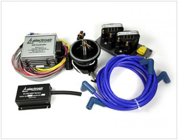
My latest final decision was what electronic ignition system I was going to go with.  I’ve had reports from a number of friends & builders, and scoured the forums to finally come to my decision.  I also spent hours at each booth during SNF13 to figure this out.  In fact, before they closed their doors, I had spent a fair amount of time on the phone with the guys at Mattituck Engines discussing electronic ignition systems for experimental engines.  My final decision for my ignition system is an Electroair on one side paired with a Slick magneto on the other.

Chap 23 - Electroair Electronic Ignition

And although it may sound silly or incompatible to some, after a discussion with a few engine gurus I’m holding out the option (and will research) in the future to replace the Slick mag with a PMag.


Chapter 23 – Engine Ram Air System

In early September I went with a one-off type component: Rod Bower’s Ram Air System. Normally Rod works with the RV gang, but I spoke with him at length about using this on a Long-EZ, and I think this is the polished, albeit more sexy version of what James Redmon built (himself!) for his Berkut.  And since James’ Berkut is literally one of the nicest canards in the world, I gotta have something nicer than him!  Ha!

If I haven’t explained it previously, a Ram Air system is fairly straightforward in operation and does what it’s named: It simply takes an external, isolated source of air and rams it into the intake manifold via the fuel injector servo WITHOUT being filtered.  Yes, I did say it’s UNFILTERED AIR being RAMMED into the engine intake.

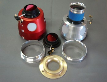
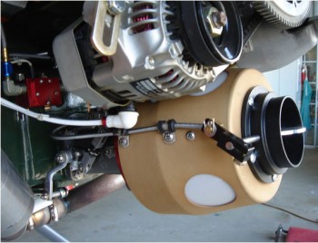
“Ok, is that smart?” you ask.  Of course not!  At least not on the ground!  Ahhh, so the beauty of Rod’s system is that you throw a lever (or a servo switch) and a butterfly valve closes off the outside air source.  The air, then, is brought in through the 4 reed valves on the side of the aluminum coffee-can sized housing that just so happens to have a K&N filter therewith inside.  Thus, on the ground, or close to it, the air is in fact filtered.  Bit once airborne, the valve is opened to let the ram air do its magic, ala Red Bull Racers, thereby providing anywhere from about 1–1.5 inch gain in manifold pressure.  Brilliant!

And here’s what it looks like:

Chap 23 - Rod Bower Ram Air SystemAnd installed on a tractor setup:

Chap 23 - Rod Bower Ram Air System


Chapter 23 – Engine

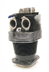
Today I ordered a set of 4 ECi Tapered-finned Nickel+Carbide Cylinder Assemblies for my IOX-340S engine.  The set also includes 9.5:1 compression pistons.  Since I picked up the engine case, the crankshaft & camshaft a few weeks ago, I’ll start purchasing the accessories over the next year so that when I get back I can put this thing together with Tom Schwietz.

A nice thing about buying the cylinder assemblies as a set is that ECi ensures that all the cylinders are flow matched, making for a much smoother and efficient engine.

Here’s a representative pic for context.

ECi IOX-340S Cylinder Assembly


Chapter 23 – Engine/Starter

Besides starting to pick up the main parts of the engine, in July I also started down that long road of picking up all the engine accessories as well.  There were a few components that I still wanted to do a fair amount more research on, to be sure I was getting what I felt was the best fit for my engine and airplane.  Of course I read a ton & made quite a few phone calls to some really smart folks.

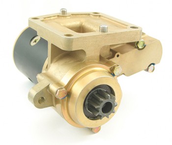
One thing that I new for certain was that I was going with a B&C starter.  While B&C starters ARE NOT the lightest starter you can get out there (by a few pounds), from every bit of feedback I could garner these guys are bulletproof.  Thus, a B&C starter was the first engine accessory that I pulled the trigger on (example pic here).

Chap 23 - B&C Starter


Chapter 23 – Engine

I’m back in the States for a couple of weeks before I head over to the Sandbox.

Today I pulled the trigger on my Lycoming O-320 engine case along with an ECi IOX-340S strokered crankshaft, balanced connecting rods, and camshaft from Tom Schwietz at Aero Engines in Winchester, VA at Winchester Regional Airport (OKV).  I met Tom at his shop and talked with him at length on various engine options, the build, etc. and toured his shop.  Tom was incredibly knowledgeable and the facility was quite impressive.

However, since I apparently had a huge brain fart and failed to get a picture of my new engine components, I tried to find a good representative picture online but couldn’t find anything fitting.

Yesterday, I got to spend all afternoon/evening with my buddy Marco down in Virginia Beach and tour his build facilities as well (impressive garage my friend! ha!).  He showed me his Long-EZ project and of course we talked Ad nauseam.  I also dropped off my TIG Welder for him to try out, evaluate & use while I’m gone this next year.  If he likes it he’ll most likely use it build his rollover assembly.  It was great to visit with him and get some good Long-EZ shop talk in with my fellow Canardian.  Build on my friend!


The Whole Tamale!!!

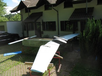
Today I pulled out all the stops . . . or should I say I pulled out all the pieces of the build so far.  Before I am separated from my project while I spend a year in the Middle East for Uncle Sam, I wanted to get an idea of what this thing looks like put all together.

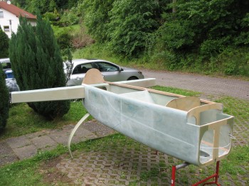
So I pulled the fuselage out into the front yard, and kept it covered while I collected the other components.  Next up was the Centersection Spar which I placed into the fuselage for the first time since I completed it about 8 months ago.
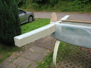
Chap 14/15 - CS spar & firewall mockupChap 14/15 - CS spar & firewall mockup

You can see in the pic below that I got the measurements correct for running the rudder cable conduit through the fuselage sidewall, then through the CS Spar and positioned just off the edge of firewall (the curved metal conduit bracket that the Nylaflo will run through will get mounted to the firewall).
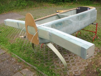
Chap 14/15 - CS spar & firewall mockup

I’m jumping ahead with the following pics below since they were at the tail end of the this grand mock-up as I was tearing it all apart, but I wanted to keep like pics together.
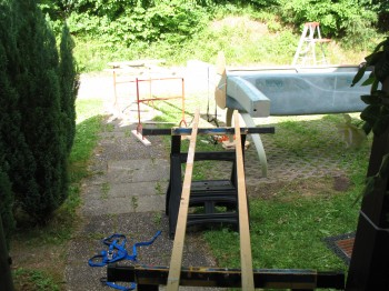
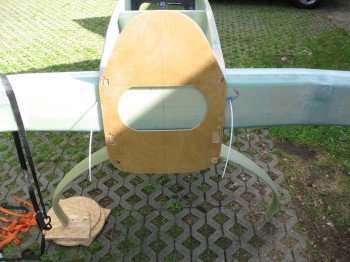
Chap 14/15 - CS spar & FirewallChap 14/15 - CS spar & FirewallChap 14/15 - CS spar & FirewallChap 14/15 - CS spar & FirewallChap 14/15 - CS spar & FirewallChap 9/14 - Main Gear & CS spar

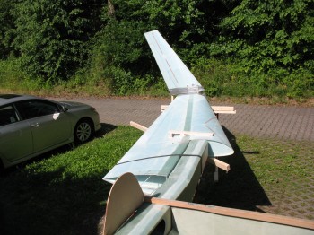
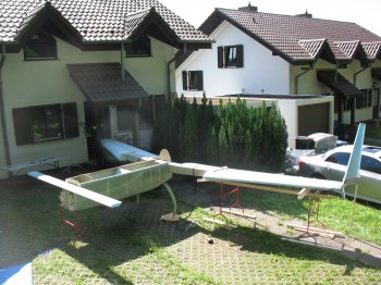
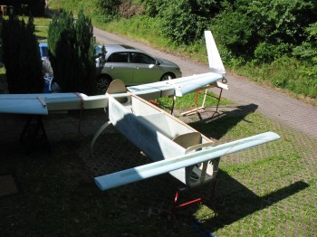
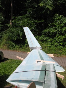
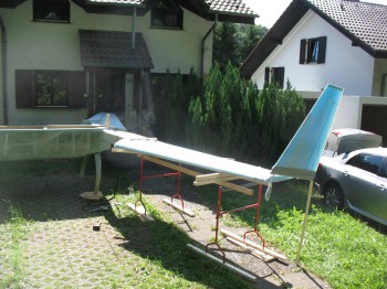
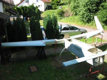
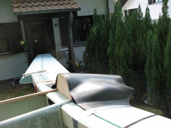
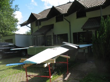
After I got the CS spar & firewall in place, I added both of the wings next.  Again, besides the measurements provided to me in the plans, and of course a couple dozen confirmation measurements, I had not lined up either wing with the CS Spar to confirm that the hard points (aluminum extrusions) lined up with each other.  Obviously, I was very relieved to confirm I hadn’t jacked any of my measurements up!  Also, as you can see I had to throw on at least one winglet just to get an idea of how it would look.  Although it was a little awkward to get it on the end of the wing so it looked half-way normal, I think I got in the ballpark.  Well, and of course we can’t forget the canard… yes, it’s on there too!
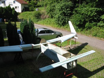
Long-EZ Project Mock-upChap 14/15/19/20 - CS spar-firewall-wings-wingletLong-EZ Project Mock-upLong-EZ Project Mock-upChap 14/19/20 - CS spar-wings-wingletChap 19/20 - Wings & Winglet mockupLong-EZ Project Mock-up

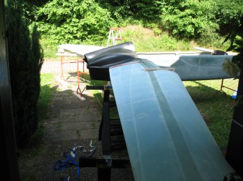
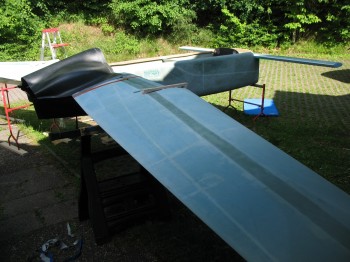
Once I got the pics above taken, now it was time to fill in what gaps I could to make it look at least a little like it had some mass to it.  Next came the engine cowlings.
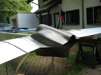
Chap 19/23 - Wings & Cowling trial fittingChap 19/23 - Wing/spar & Cowling fit

The wind had picked up a little bit and I didn’t want to damage anything just to get some pictures, so I removed the Left winglet & put it inside the garage.  “What about the Canard?!”  You may ask.  Well, no worries of the wind playing havoc with the canard dear readers, for I clamped the mounting tabs to the front fuselage bulkhead, F22.
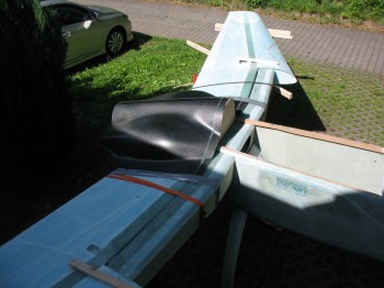
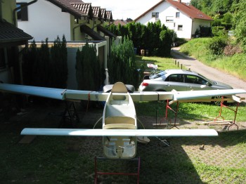
Chap 19/23 - Wing/spar & Cowling fitLong-EZ Project Mock-upChap 10/19/23 - Canard-Wing/spar-CowlingChap 10/19/23 - Canard-Wing/spar-CowlingChap 19/23 - Wing/spar & Cowling fitChap 10/19/23 - Canard-Wing/spar-CowlingIn the next couple of shots you can see how the lower cowling hangs down 4 inches below the stock/plans firewall.  Again, since Mike Melvill had built a NACA inlet for his engine air intake the back end of his fuselage–and subsequently the firewall–was 4 inches lower than plans [in essence making the bottom line of the fuselage continue straight until aft of the firewall].
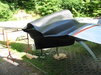
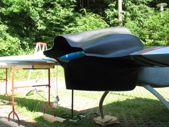
Chap 23 - Cowling Trial FittingChap 23 - Cowling Trial Fitting

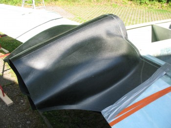
And then the following pics are more close-up shots of the upper cowling.
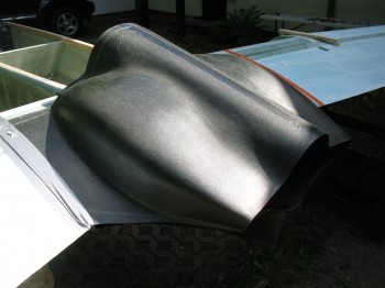
Chap 23 - Cowling Trial FittingChap 23 - Cowling Trial FittingChap 19/23 - Wing/spar & Cowling fit

Finally, after I broke everything down and got the wings, canard, cowling & firewall back inside out of the sun, I spent some time looking at the CS spar, taking some measurements and looking at how square it was to the fuselage (this was a quick mock up to keep all the parts in the sun as little as possible–about an hour total time . . . and if you actually look at the shadow of the house on the mock-up from start to finish, there’s not that much movement).  At this point the CS spar and the fuselage were in the shade provided by the sun going down on the other side of the house.
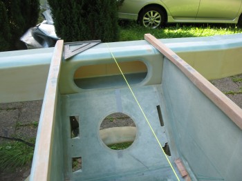
Chap 14 - CS spar trial fitChap 14 - CS spar trial fit


Chapter 11 – Elevators & more

I was busy working move stuff much of the day, so I left the elevators bondo’d to the table to cure even more.

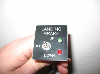
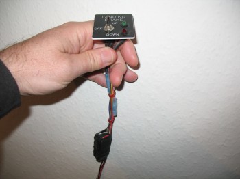
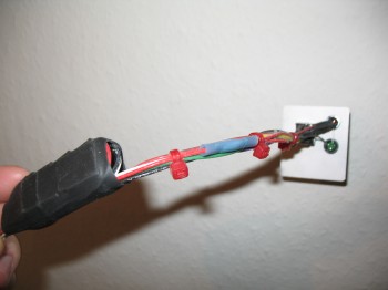
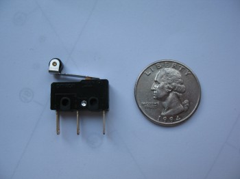
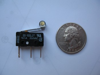
My buddy Marco asked me to take some pics of my Landing Brake Switch that came with the landing brake setup I got from Jack Wilhelmson at eznoselift.com.

I took a pic of the switch & its wiring, and the microswitch that is used in the system as well.

Section VI - Landing BrakeSection VI - Landing BrakeSection VI - Landing BrakeSection VI - Landing BrakeSection VI - Landing Brake

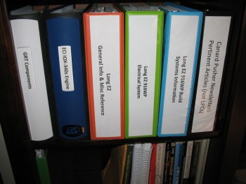
And since we had been discussing the process of researching Long-EZ construction, I shared a picture of my project documentation binders & research.

My Long-EZ Docs & Reference Material


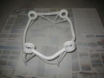
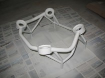
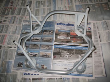
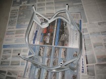
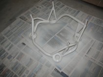
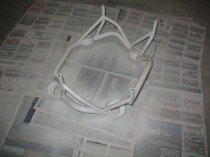
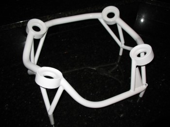
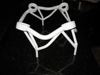
Painting Engine Mount

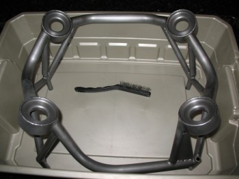
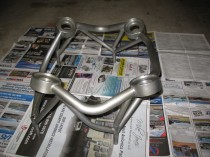
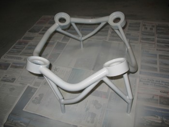
Tonight I finally rolled up my sleeves, grabbed a can of WD-40 rust remover, my disposal econo-pack of wire brushes from Harbor Freight and went to work.

Chap 23 - Engine MountChap 23 - Engine Mount

Chap 23 - Engine Mount

Chap 23 - Engine Mount

Chap 23 - Engine MountChap 23 - Engine Mount

Chap 23 - Engine MountChap 23 - Engine Mount


SNF – Engine Mount

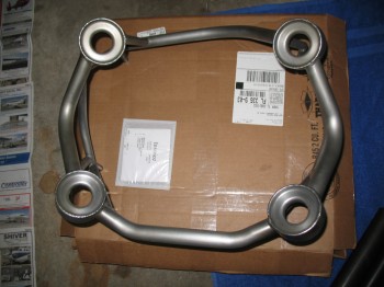
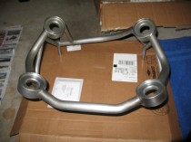
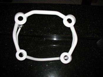
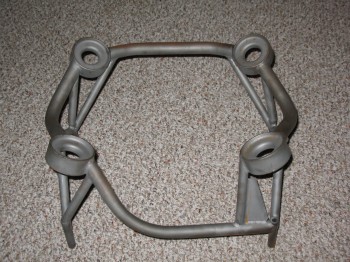
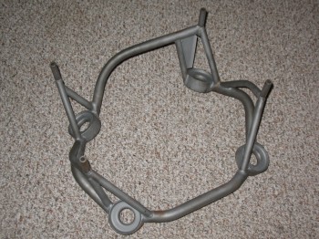
I found Randi & Chrissi of Cozy Girrrl fame today to pick up my engine mount that I had ordered from them last month.  Looks good.  I think the humidity and the amount of time between it getting built and me picking it up allowed some surface rust to form a bit.  No worries, I’ll knock that off and paint it so it will stay corrosion free until I use it.

Chap 23 - Engine MountChap 23 - Engine Mount