Chapter 21 – Coordinating & Planning

Be forewarned, there are NO pics in this long post! [Might want to grab a cup of coffee…]

Today turned into an all day planning, coordinating and all around down a dozen different rabbit holes day.

I’ve been having a back & forth email discussion with my buddy Dave Berenholtz on, well, just about everything involved in the build, but today specifically was on the sump tanks and the fuel system.  I haven’t really communicated my fuel system since I have been researching, studying, and planning it for literally 4-5 years now.

Thus, today was the day to polish off the particulars on my fuel system and get it finalized so I can implement it.  To understand my fuel system planning, I will be throwing out some big names in the canard world…. not to name drop, but to show the pedigree (not mine) and experience of those involved in this discussion.

It started a number of years ago as I was talking to Marco on the phone and sent him a link to Wayne Blackler’s Long-EZ to make a point as to what I was on about.  After a few minutes he simply declared over the phone: “He has no external sumps.”  He noted something I had failed to notice, and we pondered over that a bit.  I bit later I discussed with Wayne his “no-management” fuel system, as I did with Ken Miller, Bill James, and Vance Atkinson, among others.  So, although I started out ready to install the plans version fuel system, I made a distinct departure from that plan and decided on a GIB thigh-mounted central sump with no fuel selector valve system.  I was going no-management all the way Baby!

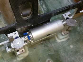
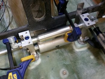
Well, my planning was geared towards the no-management fuel system for years when last year before RR I made one final search online before installing my EFII fuel pump right below the CS spar…. and I mean it was going literally on the bottom surface of the CS spar, centerline.  I have to say I had a nagging feeling about putting all that weight back there (it’s 2.5 lbs), and when I saw a pic of Joe Carragio and few others who had mounted there fuel pump under the pilot thigh support, it got the gears in my brain turning. Hmmm…

I did a quick mockup of the fuel pump up in the pilot thigh support area and realized it would fit perfectly.  Hmmm….  Ok, well a big reason that I was going with the no fuel management system was the integral GIB thigh support sump, meaning: no external sumps.  Why is that important to me?  Simple. I have the Berkut-style armpit engine cooling intakes on my cowlings.  These sit literally inches behind the plan’s external fuel sumps.  This means not only accepting more drag in general, but bringing disrupted, disturbed, burbling air into my engine for cooling.  Not optimal.  The no management thing, well, that would be nice.  Of course, that came with a decent, unique risk all its own. But added drag and disrupted engine cooling air! Well, I was not willing to accept that when I could simply move the fuel from an inch away from the GIB to an inch away from the GIB (IMO!)

Fast foreward.  After pondering it for a number of months, looking at the pros & cons, I decided to do what “we” in Washington, D.C. are best at: COMPROMISE!  I decided to go GIB thigh support sumps (yes, plural) by simply not making the mouse holes that would normally be made in the center rib of a single tank sump.  I then would use the Andair fuel valve I bought many moons ago –since I was adding fuel weight going forward anyway. Moreover, since I needed a fuel line going to the pump, and a return coming back, what was the complexity or weight of one more?

The bottom line is I will be going with a hybrid fuel system.  No external sumps with internal fuel sumps under the GIB thigh support (yes, I know the arguments of “bringing fuel into the cockpit” . . . and clearly I’ve weighed all my pros & cons, and risks & benefits). I will however keep the separate tank concept by running the fuel through the Andair L-R-OFF fuel selector valve.

Today I confirmed installation requirements with EFII for my fuel boost pump and Precision Airmotive for my Silver Hawk EX fuel injection system.  After getting questions answered regarding size and location of filters, and fuel pressure sensor connection info, I finalized –after 7 years– my fuel system!

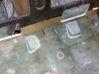
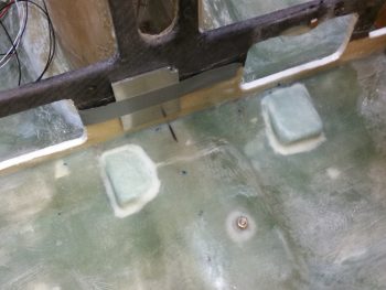
Now, to throw yet another wench in the works, I’m strongly considering knocking out my internal fuel sump in the back seat, which would then allow me to ACTUALLY run my fuel lines for the left & right sump feeds to the fuel valve.  In addition, that would clearly give me the info on spacing requirements I need for fuel lines, wiring, etc. going down the right sidewall.  This would also give me all the real world clearance specs I need for the pilot thigh support ribs and configuration, under armrest configuration for the right side, etc.

I will sleep on it, but I am strongly leaning in that direction as my next move.

Also today, besides updating my fuel system diagram (last updated June 2014) and my firewall components & wiring placement & configuration diagram (last updated Feb 2014), I also updated the fuel system wiring diagram and the engine information/management system wiring diagram.  That may not seem like much, but the phone calls and digging into the manuals and websites to confirm, verify and update components, do analysis on part selection, prices, check inventory, etc. . . .  well, that all consumed about 6 straight hours.

I then spent a good hour sitting in the back seat, marking up my thigh support requirements, and then trying to guesstimate how to translate that over for the passengers I’ll be carrying.  As a comparison, the thigh support mod spelled out in CP 28 has the front wall at 37″ forward of the firewall, 4.5″ high, and then tapering back 6″.  Before climbing into the back seat I looked at Dave B’s sump tank, which is a little too robust for me (in all fairness, he called that), and Bill James’, all online of course.  I then looked at the Berkut GIB thigh support sump plans, reread emails from the whole gang I mentioned above, and then after a few machinations dialed mine in at 35.5″ forward of the firewall, with a height of 6.2″ and tapering back around 10″.  I’ll continue to work out the particular specs over the next day or two, and then make my decision on whether to break ground on this part of the build or not.


Chapter 13/17/21 – It’s the little things…

that you end up spending a ton of time on during these builds!

Today was, in fact, all about a bunch of little things. Yes, again!  If you get tired of reading about ’em, trust me, I get tired posting about ’em!  Ha!  But, of course, the myriad of little things combined is what creates an airplane in the end.

I started off by prepping the two hard points for the pitch trim actuator to be glassed over with 2 plies of BID.  Here’s the before pic of how it looked when I started.

And then after a few minutes of good sanding.

I then cleaned it up & prepped it for glassing.

I was going to use foam to fill the space in-between the two hard points and the around the aft side of the small hard point, but it turned out to be more trouble than what it was worth.  At least in my opinion.  So, I just made the flocro a little dryer so it wouldn’t run and used it as the filler all the way around.

I then prepregged 2 plies of BID and laid them up.  I also peel plied those areas that would easily take peel ply without a hassle.

With the leftover epoxy I added a little more to the bit of flocro I had and made primarily a micro mix.  I spread the micro on both the left & right side nutplate assemblies used to secure the upper fuel pump attach bolts in place.  I then laid up 1 ply of scrap BID over each of the nutplate assemblies and peel plied the BID.

After I knocked out the fuel pump nutplate assemblies layups, I did do one more task (not pictured) with the leftover epoxy: I mixed it into thick flox –only flox– and sealed the parts of the bolt holes in the pitch trim bracket where I had drilled them out in search of the right position.  Their latest position had each of the bolts covering about 60-75% of there own hole edges, so instead of cutting a whole new bracket, I decided to flox up the open areas of the holes and leave the bolts alone in their own holes.

Then, while all the composite stuff cured, I set my sights back onto the Andair fuel selector valve. I took the valve lever and cover off to assess how it will get mounted to the fuel valve bracket & cover.  I also wanted to double-check that the K1000-3 nutplate mounting holes were countersunk for the rivets, which they were.

I then riveted 3 each K1000-3 nutplates to the Andair fuel selector valve.

I set the fuel selector valve back in place and will assess it more fully later on.

I ran out to run some errands and when I returned all my composite tasks of the day had cured.

I pulled the peel ply from the pitch trim actuator mount hardpoint layup and cleaned it up a bit.  I then redrilled the holes and removed the protective saran wrap I had placed in the holes to keep unwanted epoxy out. I then tweaked the glass around the holes just a bit more to allow for each respective bolt to fit back into their hole.  I then test mounted the pitch trim actuator bracket back onto its new hardpoint base.

If you’re thinking 2 plies of BID might not be robust enough for the pitch trim bracket, no worries!  When I glass the nose top in place these hard points, being right on the edge, will get another 2 plies of BID over them.

Here are both the left & right side nutplate assemblies used to secure the upper fuel pump attach bolts after their layups cured.  I realize it looks like a lot of micro is covering these nutplate assemblies, but there really isn’t that much.   The thickness of the phenolic combined with the back side of the nutplate, rivets, etc. makes it look like there’s a ton more micro than there really is.  Admittedly, there is a bit more micro on the right side nutplate than the left.

I actually assembled the tool box earlier in the day, but since I made a video showing its operation I put these tool box pics at the end of the post.

The following video discusses not only the tool box operation, but I also cover the pitch trim actuator hard points layup for a bit.

I still have number of small task items on my list, but I’ll keep pressing through to get them done.  Eventually I’ll of course get back to the big stuff!


Chapter 13/21 – Fuel pump installed!

Tonight I continued my roundabout quest to get the nose components in place with the prerequisite task of finishing up the pilot seating area to be able to determine –with a high degree of accuracy– where those nose components should be placed for knee/leg clearance, ergonomics and reachability.

I started out by drilling out the front side mounting holes on the fuel pump to 5/16″ diameter to allow me to slide the hex head cap screw through the front to then hold the fuel pump in place.

After drilling the front side of the fuel pump frame for the 2 top side mounting screws, I mounted the fuel pump . . . officially for the first time!

Here’s a close up of the hex head cap screw/bolt securing the top of the fuel pump in place.  As you can see, I still need to micro & glass the nutplate assemblies into place.

Here’s a shot of the aft left side mounting hole that I drilled out to 5/16″ & tapered with a large 3/4″ countersunk bit for ease of getting the mounting bolt inserted.

I wanted to ensure that all the pieces of my fuel hobby project here would fit together, so I cut a 3″ piece of 3/8″ 3003-0 aluminum fuel line tubing and collected up some fittings to connect the fuel pre-filter OUT to the fuel pump IN line.

With such a small piece space in the flaring & bending tools were TIGHT, but as you can see I was able to get the flares made & tubing bent to connect the pre-filter to the fuel pump.

Here’s another shot after I rotated the tubing downward about another 1/2″.

I then took a break from all this fuel system stuff and gathered up my tool box lid, located the upper latch piece and the requisite rivets.  I then drilled out the half-painted-over holes and proceeded to rivet the upper latch piece in place.

Before assembling the tool box for good, I taped up all of the lower tool box body to protect it from paint except the hinges.  The hinges required a bit of touching up since I had previously broken through to gray primer while wet sanding the lower tool box.  I then prepped the hinges by sanding them lightly (again) and then cleaned them for paint. Finally, I took it outside and hit the hinges with a couple coats of gloss black paint.  [No pics for this task].

With my sideline tool box endeavor out of the way, I wanted to get one more major task completed tonight: run the fuel line from the Andair fuel valve OUT port to the EFII fuel pump pre-filter IN port.

In reality, this task was a 2 part process.  I ended up nearly destroying the first piece of tubing I tried to install here, but then ended up using it as a prototype model to then craft the second tubing with the tubing bender vs. my ham-fisted manipulations of the tubing.  I figure this will the be the most difficult fuel line tubing connection that I’ll have to make on my fuel system.

Beside just getting this tubing piece configured and in place, my actual main goal here was to figure out the positioning of the Andair fuel valve.  As per my norm, you’d probably not be surprised to learn that I am NOT putting this valve in the plans position!  Close, but it will sit over an inch higher and well aft of the plans position.

Why?  Well, in talking to current Long-EZ flyers, and having sat in Marco’s Long-EZ, I can tell you with all certainty that I want to have the ability to SEE what position my fuel selector is set on versus only being able to FEEL the position of my fuel selector valve.  I will of course check this out and ensure I have enough seating room, but beyond any other issues, this is my main goal as far as the fuel valve configuration & installation is concerned.

My last official build act for the evening was wet sanding both the aft NG30 cover and the Garmin GNS480 GPS antenna cover.  I set aside clear coating the NG30 cover until tomorrow since there’s a couple of areas on the cover that I want to assess.  However, with the GPS antenna cover, I hit it with 3 good coats of matt clear coating (yes, crappy pic).

With that, I closed up shop for the evening and left the lovely paint fumes to themselves.


Chapter 13/21 – In RV country!

First thing this morning I pulled the peel ply off the fuel pump mounting pads.  There were a couple minor air bubbles but the layups looked good.  I cleaned up the peel ply strings a little before snapping this shot.

And then sanded the areas that I couldn’t easily apply peel ply to last night.

I then quickly checked the fuel pump fit on the mounting pads.

Before heading out on a 2-part quest I prepped & floxed the 2 larger click bonds in place onto the mounting pads, securing the fuel pump in its mounting position to keep the click bonds appropriately spaced.  I was heading over to my EAA Chapter 186 buddy & RV-10 builder, Jeff Karrel’s place for some help riveting the lower latch to the tool box, since he of course has all the big gun riveting tools required to do such a job.  The rivets on my lower tool box latch are just too low for me to get to with my hand rivet squeezer.

I also stopped by my local Village Hardware store to pick up some 1-1/4″ SS hex drive cap head screws.  Normally stores only have half-inch increments available after 1″ (then 1-1/2″, 2″, 2-1/2″, etc.) but behind all the other cap head screws they had a small box: 1-1/4″ length for apparently a previous special order!  Voila!  And they didn’t even have a price… but we worked out a price and I bought a couple and was on my way to Jeff’s in short order.

Jeff showed me his beautiful RV-10 build (that thing is HUGE!) and after about an hour of shooting the breeze we actually got to work.  Jeff pulled out a deep-necked pneumatic rivet gun and asked me if I wanted to do the honors.  I did, but I wanted him to do it so I could have yet another builder’s “mark” on my build as well!

Here’s some action shots of Jeff driving the rivets on my lower tool box latch.  Also, you can see his incredibly clean RV-10 build in the foreground.  He is just finishing up riveting the tail section to the front fuselage… exciting stuff.

One more shot of Jeff driving home the rivets on my tool box . . . huge thanks Jeff!

After another couple of hours talking shop with Jeff, I then drove home and set the tool box back in its proper spot.  I then grabbed a shot of the rivets Jeff set in place.  It’s all coming together!

I then cleaned up & prepped the 2 large fuel pump mounting click bonds for glass.

After adding a bit of flox for transition around the edge of each click bond, I then laid up 3 plies of BID over each one.  I peel plied the 2 layups and then took off to meet a buddy of mine for dinner and a movie (sorry, no pic of the peel ply on the layups).

Upon returning home for the evening I pulled the peel ply and cleaned up the layups.

I then test fitted the fuel pump mounting on the freshly installed lower click bonds on my glassed foam mounting pads.  Looking good!  One small issue that I have is that the 1-1/4″ bolts are too long to fit in the gap on the fuel pump mounting frame.  I’ll have to drill out the aft-side mounting holes –which aren’t used here– to a wider diameter to allow the bolt head to fit and slide through to the other (forward) side.

I then test mounted the fuel pump’s pre-filter to check its fit & placement.  Again, looking good so far!

Hopefully tomorrow after I drill out the aft top mounting holes to fit the upper mounting bolts in place I’ll be able to report that the fuel pump is officially mounted!


Chapter 21 – Mounting fuel pump & filter

Today I focused on mounting the EFII fuel pump and its pre-filter.  I played around with the configuration for a bit before finally narrowing both components’ locations as shown below.

With the existing fillet at the bottom aft of the instrument panel –where it’s glassed to the fuselage floor pan– I needed to have a slight gap between the fuel body and the instrument panel.  I thought 1/16″ (0.063″) would do it at first, but it wasn’t enough and still caused the bottom of the fuel pump to kick out aft a little bit, not allowing for a true vertical install.  I tried 1/8″ (0.125″) but it seemed a bit too much.  I then scrounged up some 0.093″ scrap aluminum to test as a spacer and that did the trick.

With the position of fuel pump dialed into its final position, I clamped it and drilled the top 2 mounting holes into the lower instrument panel.

I then made up 2 K1000-3 nutplate assemblies with 1/16″ phenolic.

With my fuel pump positioned, I then fiddled around with the pre-filter before I finally figured out its final position.  I then marked the spot and 5-min glued a click bond in position (after I prepped the clickbond).

I then laid up 3-plies of BID over the Clickbond after creating a flox transition around its edges.

I also floxed in the left nutplate assembly and screwed an AN3 bolt into it to hold tightly in place while it cured.  Over on the right side, due to the drilled mounting hole being so low on the lower instrument panel cross frame (top edge of map box/lower edge of leg opening) I micro’d in a half moon looking piece of H45 foam in prep for 2 plies of BID on the front side, and 1 on the aft side.


If you’re wondering about the bolt head’s close proximity to the fuel pump frame, and how it can’t possibly turn, you’ve spotted an issue.  Tomorrow I need to pick up some hex head socket cap screws to allow them to turn in tight quarters.

I then decided it was time to roll up my sleeves and knock out the hour++ trial and error process of forming respective Devinycell wedges for both the right and left side of the fuel pump.  As you can see, these foam pieces will make up the mounting pads for the fuel pump frame’s “feet,” allowing me to bolt in the fuel pump frame on the lower aft sides (vertical bolts) and the forward side (left & right as well) using horizontal bolts.

After mocking up the fuel pump countless times, with a myriad of sanding with my Perma-Grit tools (still love those things!) to shape the respective pads, I finally got the shape and positioning I wanted with the pads.  Moreover, with the pads in place and the fuel pump temporarily installed, I could checked that there was a decent gap for the eventual mounting of the bigger sized click bonds for the aft side fuel pump mounting.

I then micro’d the foam pads in place and laid up 2 plies of BID over each pad.  Down in the lower left corner in the pic below is a small square ply of BID that I glassed in placed and peel plied (along with the pad layups) to patch a small divot I had put in the floor at some point… I still had a small amount of epoxy left over allowing me to do this.

I also floxed the right mounting nut plate assembly into place (after I redrilled the hole) and held it in place with an AN3 bolt while it cured.

Below you can see a shot of the small curved piece of foam I glassed in place to help as a backer for the the right side fuel pumping mounting nutplate  assembly.

With that, I did one final check on all the layups, and called it a night.


Chaps 13/17/21/22/25 – Firing it up!

And when I say “Fire,” I’m not kidding . . . read on below!

Today I started out doing some planning and inventorying for my fuel system.  Since I’m going to make my new work demarcation line at the pilot’s seat bulkhead, going forward, then I needed to figure out my fuel system in real terms, not just in my head.  I drew out the fuel system on a white board and then did an inventory to see what I had on hand and to see what I needed to order.  I was fairly pleased that I had the majority of stuff I needed on hand, but will need to order about $35 in fittings from ACS.

I also did some research on the exact installation requirements for each fuel system component.  For example, on the Andair fuel valve I could clearly see that the big red selector handle needed to come off to install it, but I hadn’t even truly read the install manual until today to find out how to remove the handle, and install the unit.  I also had some questions on the FT-60 Red Cube fuel flow sensor that I eventually got answered on the VAF site.  In addition, I wanted to double check some info on the fuel pump.

After a few hours I was happy with my progress on the fuel system and was satisfied that I actually knew the direction I was headed with that system once again.

I then my sights back onto the Atkinson pitch trim system.  Having received my reamers via UPS this AM, I was ready to drill and ream a nice round 1/4″ hole in the elevator tube to mount the control arm of the pitch trim actuator.

First, I spent a good 45 min dialing in the new configuration and physical mounting of the pitch trim actuator by redrilling the 2 mounting holes in the mounting bracket.  Not only was I moving the entire unit aft a hair, I was also rotating the front of bracket down a bit more while the aft side dropped down some as well, but not as much as the front.

Once I got the pitch trim actuator assembly newly aligned, and the mounting hole in the elevator tube was ready to be drilled, I set up the control system within the plan’s specs with the elevators at neutral and the control stick at ailerons level, which is actually about a 5° stick grip lean to the left — again, as per plans.  I then drilled out the hole in the elevator tube and mounted the control arm of the pitch trim actuator.

Once I tested the newly realigned pitch trim system, the up trim worked fine but the down trim didn’t work at all.  Apparently, if you’re prone to moments of just being dumb, then you can expect issues like this!  Apparently, in my haste to get this pitch trim actuator in this bird, I forgot to double check its current position.  Since the actuator arm was all the way in, then when I threw the switch for it to push the elevators up, it did so with no issue. But then when I went the other way, well, by the time the actuator throw ended the elevators were merely back at level . . . and didn’t go down below the level line at all.

Another issue I had was just a little battery fire, or so I thought –after I removed the actuator to set it at its midpoint position– as I was coming around the nose and had moved the actuator power wires.  Well, as I rounded the nose I could see a bit of fire right on top of the battery.  Not sure what was actually burning, I yanked the wires off the battery and kicked it across the floor so if it decided to do something violent I had the fuselage between me and it.

Well, the fire went out immediately, but there was a good bit of smoke.  Apparently one of my patch cords shorted out and literally blew apart and started burning.  It’s interesting that none of the mil spec wires had any issues, but a couple of the cheaper leads were destroyed.  A few minutes later I felt the battery to see if it was warm, and it wasn’t.  I then checked voltage on it and it was a bit low at 12.59 volts.  But then again, I haven’t charged it in a few weeks and I have been using it a lot.  An exciting little sideshow to be certain, but with that out of the way, I got back to the task at hand.

After about 10 minutes of having the garage open and a fan turned on to clear out the smoke and smell from the burning battery wires, I went to work to fix the actuator configuration by simply taking the actuator out of the nose and extending it until it was half out (1.5″ out, with a 3″ total extension).  I then remounted it, verified and reset the control system to specs, and the drilled the new hole.  When I tested it the second time around it worked like a champ (see video below).

With the pitch trim actuator install taken care of for the most part, I then turned my sights back onto getting some of these painted parts knocked out.  I wet sanded the tool box lid lightly with 500 grit sandpaper, then 1000 grit and finally 1200 grit.

As I buffed out the tool box lid I was also uploading the lengthy video above.  It took a little over an hour total to buff out the tool box lid by hand.

Again, after the Ultimate cutting compound application, I then wrapped up the tool box lid by hitting it with 3 rounds of Meguiar’s Ultimate Polish.

I then set it on top of the tool box body.

Finally, my last task of the evening was to wet sand & Simple Green wash the GPS antenna cover.

After I prepped it for more paint, I hit with 3 coats of white primer/paint to cure overnight. This antenna cover will not be a gloss color, but rather either semi-gloss or even flat.

I’m heading into the weekend tomorrow and have plans tomorrow afternoon on, but I will continue to try at get all the nose components installed –including the now prerequisite pilot cockpit area– to allow me to build the nose top.


Chap’s 13/16/25 – Course deviation

I started off today sanding down the aft NG30 cover with some 220 grit sandpaper (sorry for the blurry pic).  I then needed to add a tiny bit of Metal Glaze to a few spots for some minor blemish cleanup.

I had also spent a little bit sanding down the GPS antenna cover as well, and it too need a few dabs of Metal Glaze for some blemish cleanup.  In addition, you just might be surprised how intricate the sanding job is on this thing, just to get what is seemingly a fairly simple & basic shape.

Here’s the other side that I also hit at the lower edge with some Metal Glaze.

As the Metal Glaze was curing I then grabbed the tool box body and redrilled the 2 rivet holes on the front face that will be used to mount the lower latch assembly.

Speaking of which, here is the lower latch assembly right here.  I quickly realized that my rivet hand squeezer didn’t have a deep enough arm to allow me to set these rivets.  Guess I’ll have to track down some RV buddies in my local EAA chapter!

Shortly after setting the lower tool box latch in place, I took the dried GPS antenna cover and the aft NG30 cover outside and hit them with high build primer and 3 final coats of paint, respectively.  On the NG30 cover, I was only retouching the left side and front, so I added 3 more coats of paint since I’ll be giving it a good wet sanding before clear coating it.

As I was working on trying to find alternate solutions and locations for the pitch trim actuator unit, I realized that to do this right I really need to be able to test out any potential obstruction or tight fit that a component may pose north of the Instrument Panel.  There’s just one issue with this however: when I sit in the pilot’s seat that itself constitutes an estimated best guess as well, since I have no mounted thigh supports, and no actual seat cushions, etc.  In other words, I’m set to make foundational decisions on what goes where in the nose based on a very loose estimate of my seating position, which in some instances is very critical to figuring out what goes where without having my knee constantly banging into something during a flight.

This drove me into yet another mini-epiphany.  I need to institute a slight change of direction, with a compass heading just a few degrees off of current.  In other words, before I can really press on with getting the nose components in place and dialed in properly, I need to get the pilot seat area squared away.  Thus, I need to work from just a bit more aft forward to get this all right.

So, the first thing I did was to figure and mark up the notch in the right arm rest for the Dynon Intercom unit.

I then cut out the notch in the right arm rest for the Dynon Intercom unit.

Here’s another shot of it.

Since I was in the cutting mode on the right arm rest, I decided to finally finish what I started about 5 years ago and widen the seat belt access opening to the plan’s specs. The reason why it looked the way it did above is actually a little comical: I simply read Burt’s forward dimension as 19.5″ vs the actual 14.5″ . . . resulting in a much narrower seat belt access slot.

Here’s the GPS antenna cover with 3 more coats of primer, which it will need to help finalize its shape.  After I give it a good wash, barring any more shaping requirements, I’ll hit it with a couple of coats of dull off-white primer as the final coat & color.

Here’s a pic of the aft NG30 cover with it’s 3 latest coats of paint on the left & front sides.  I did manage to get one run in the upper left corner on the side, but it should be no big deal since I’m going to give this a good wet sanding, then 2-3 coats of clear coat.

Here’s the front side of the aft NG30 cover.  Again, I’m going to wet sand the entire thing here in the next few days before hitting it with clear coat.

I’ll of course continue to work nose component installations, but to really dial in the nose component placements on such critical items as the pitch trim actuator, I’ll be working on both the left and right armrest consoles, and the thigh support areas in between.


Chapter 13 & 25 – He’s gone!!!

Yep, the PROBLEM CHILD FROM HELL is gone!!!  Yeah!

Of course I’m talking about the Tool Box Lid.  Ah, yes, I will regale you with that story in a bit, but first . . .

After updating a few more electrical diagrams this morning I went on a quest to find a reamer to rework the pitch trim actuator assembly arm attachment to the elevator control tube.  I was taking some Meguiar’s cutting compound back to Harbor Freight for a refund since I found it for $7 cheaper at Walmart.  I was also hoping that maybe Harbor Freight might have reamers, but alas, they did not.  But I did pick up some more supplies, mainly for buffing out the paint on my painted nose components.

I also ended up going to Walmart, but I didn’t pick up the exact Meguiar’s (Ultra-cut Compound #105) that I had returned at Harbor Freight.  I had heard good reports on Meguiar’s Ultimate Compound, which Walmart had in stock and for a way lower price I was willing to give a try.  I then tried big Blue and big Orange for reamers … nada.  I even took a long detour on my way home and gave Sears a try.  Zilch.  Ok, look out Internet! I’m coming back to you to order a friggin’ reamer…. (sigh).

Back at the house I only had a few hours of shop life in me, so I decided to put my newly acquired toys to good use and see how well they would perform.  I started by wet sanding the tool box body with 500 grit, then 1000 grit, and finished with 1200 grit.  I could have gone to a higher grit, but I wanted to see if the 1200 wet-sanded surface would buff out nicely.

Well, I have to say I think it did!  Now, I could have used a dual action electric buffer but I really didn’t want to end up cutting through the paint (Rust-Oleum is a bit soft as paints go) so I used the old fashioned elbow grease method on this puppy (or, maybe that’s shoulder grease method because that’s what hurts the most!!)  It took me about an hour total as I worked each section (side, front, corners) with good overlap in-between.  I used a basic wax applicator pad to apply the cutting compound, and a microfiber cloth to remove it.

After I got it all buffed out, I then switched to a new applicator and cloth to finish out the process with a couple of applications of Meguiar’s Ultimate Polish.  I have to say, for what was essentially an experiment this was certainly a success in my book!

Here’s another shot of me doing the ‘ol “can I read the print in the finish?” trick.  Obviously you can, and I am of course very happy with how this buffed out.  I will say that it’s actually difficult in the pics to get the black color to show up.  In person you can really see the black color first, and then the nice shiny reflection in the color.

I then mounted the tool box and grabbed another shot of it, hoping to get more of the black color to show up.  I think it did just a bit more here vs. the pics above.

I then repeated the buffing process for the forward NG30 cover, except since I didn’t clear coat this piece I very lightly wet sanded it with 500 grit before almost immediately jumping to 1000 grit.  I then finished up again with 1200 grit.

Between the white color and this piece not having been clear coated, you can see that the final shine is not nearly as stunning on the forward NG30 cover as it is on the tool box.  No worries at all since this piece still came out very nice, and since it will be down at the bottom of the nose well it really won’t be a centerpiece item or noticed as much.

Also, this finish on the forward NG30 cover does tell me though that I will be wet sanding and clear coating the aft NG30 cover before it gets installed back in place.  Here’s another shot of the forward NG30 cover after I buffed it out.

And one of the forward NG30 cover set in place where it will get installed.

Ok . . . then came the crowning moment of the entire last couple of weeks!!!  I finally was able to get a good wet sanding accomplished on the nose tool box lid!  I then carefully cut and placed the label on the top after measuring it out to ensure it was centered.  I then quickly wiped down the entire lid with some Acetone to ensure I didn’t get a repeat of the mysterious contamination I had last time.

I then grabbed the can of Gloss Clear Coat, shook the living crap out of it, and started with a very light mist coat over the top of the tool box lid to give the clear something to grip to on the slick label surface.  I waited a little over a minute than hit it with just another, very slightly thicker mist coat.  I then waited about 2 minutes before hitting it with its first real coat of clear.  After that, I gave it 3 more good coats for a total of 4 coats of clear, with about 4 minute intervals in between.  Normally I would go with 2 coats of clear, but with the label on top I wanted a little bit higher build for wet-sanding before buffing it out.

I thought I’d leave you with a final before & after shot of the tool box body.   I really am very pleased with how well it turned out.

So, although I didn’t find my reamer (I’ve resorted to ordering it online), I’ll mark today down in the book as a good build day!


Chapter 22 – Pitch Trim System Mounting

I started off today checking the clearance for both sides of the pitch trim actuator and realized that in extreme forward and aft stick situations, the elevator control tube had its motion limited by the corner panel reinforcement plate that I added.  I marked the corner plate and then Dremeled out the offending area (camera side of the magenta line).

As you can see, before actually starting I wedged a leather glove in place above the control tube to keep from inadvertently nicking it with the Dremel.  Before I did any cutting, I also taped a spare piece of small angled aluminum to the blue control stick cable to protect it as well.  Of course, I forgot to get an after pic, but it’s pretty much a shot of everything from the magenta line out simple not being there.

So here’s a shot of the first significant mod of the pitch trim actuator bracket, which I’m calling “Mod 2”.  Note that I pulled the swivel bracket from between the sides of the U-channel bracket and mounted it up top.  This really got the pitch trim arm up where I wanted it, at a line above the big yellow power cables.  Also, I did play around some with the bolt hole positions before moving on to “Mod 3”.

For Mod 3, I redesigned a whole new 1/8″ 2024 aluminum bracket.

I drilled the mounting holes and then removed the area on the top plate where the actuator will fit into.

I then mocked it up and marked where a second hardpoint will go into the sidewall.  This will help alleviate the stress on the front bolt from the forward and aft pushing & pulling action (which places either forward or aft twisting action on the mounting plate).

I then located and drilled the hole for the second pitch trim actuator mounting hardpoint.

After the second pitch trim mounting hardpoint was cured, I then pulled the plate and marked it up for cutting to reduce its footprint and shave off a little weight.

Here’s the pitch trim actuator mounting bracket reinstalled.  Note the second, smaller, bolt holding the aft side of the bracket securely.

I then reattached the swivel bracket atop the sidewall mounting  bracket.

And finally, here are a couple of shots showing the installed pitch trim actuator unit.

And one more shot that provides a good view of the mounting bracket assembly.

I thought this post would contain overwhelmingly good news on my pitch trim actuator installation, but it looks like more mods will be required.  As you can see in the video, since the nose sides curve inward at a fairly decent rate from the instrument panel forward, then aligning the pitch trim actuator in line with the elevator control tube is simple impossible to do in a Long-EZ (it may be doable in a Cozy, I don’t know) . . . at least this Long-EZ.

So, as you’ll see in the video, after trying different ways to mount the aft end of the pitch trim actuator arm to the elevator control tube, I eventually had to settle on mounting the rod end onto the inboard side of the control tube clamp bracket that Marco made for me.  Unfortunately, that created another issue:

Obviously I still have some more work to do to dial in the pitch trim unit so that it will be fully functional as designed . . . thus, the slog continues!

Chapter 13/22/25 – Pitch trim actuator install

I actually took the first 2 pics yesterday, but since I was heading out to meet some friends, and was trying to field an influx of phone calls, I missed my window to mount the pitch trim hardpoint into the sidewall.

No worries since it just gave me more time to figure out my exact plan on how to embed the pitch trim hardpoint into the right sidewall.  Below you can see that I started drilling out the hole where the hardpoint will get floxed/micro’d/flocro’d into place.

Today I finished the pitch trim actuator assembly hardpoint install, although when I got home my phone was dead, and it being my current camera I didn’t get a few key intermediate pics… and I really needed to proceed with this install since I’m falling behind schedule on this build!

I took a scrap piece of wood, drilled a 1/4″ hole into it, then covered the outboard side with packing tape.  Not shown is the clamp and the wedge that I used to keep the head of the bolt fairly parallel with the aircraft CL, and the face of the mounting hardpoint near 90° vertical.  This pic was taken a little while after I had removed the clamp and the wedge, when clearly my phone was recharged.

While I let the pitch trim mounting hardpoint cure, I wet sanded the tool box with 500 grit wet/dry sandpaper, let it dry, then mounted it, and hit it with 2 good coats of clear coat.

While the lower tool box body clear coat was drying, I then wet sanded the tool box lid, which of course proved to be a bit more stubborn than the tool box body in smoothing out the surface imperfections.  I got to a point where I just needed a bit of clean up around the corners when of course –although being VERY careful– I broke through the black paint to the primer below.  This tool box lid truly is proving to be the problem child from hell!  So, I dried it off and hit the corner edges with 2 more coats of black paint.  I’ll let it dry a few days before wet sanding it again and hopefully getting a few good coats of clear on it!

Here’s another something that I didn’t get a pic of earlier.  Apparently, when I drew my install point target circle, the geometry of how the mounting hardpoint fit into the sidewall was different when I could actually test fit the hardpoint piece IN the sidewall.  The original hole started in the lower left corner in relation to where I eventually mounted the hardpoint, which of course meant backfilling the open area of the hole with spare Divinycell foam.

I also knew that even though I drove the position of the mounting hardpoint as far forward and up as I could, that I still may very well need to rewicker the mounting bracket to get the spacing and/or alignment of the pitch trim assembly correct.  In addition, I know this hard point install won’t win any beauty contests, but just keep in mind that this will all get sanded, floxed, and covered with 2-3 plies of BID when the nose top gets constructed.

Here’s a downward shot of the pitch trim mounting hardpoint showing the mounting face of it straight in comparison to the sidewall.  Also, although hard to tell in the pic, the face is also vertical where the sidewall tapers out slightly as its height increases.

With the micro & flox pretty much cured, I then attached the mounting bracket to test fit this sucker!

I took about 10 minutes to file down both the top & bottom edge of the swivel bracket to allow for a better fit inside the U-channel mounting bracket.  Below you can see it swiveled inboard.

And here it’s swiveled outboard.  If it doesn’t look like it’s swiveled outboard much, you’d be right!  I still need to shave down the width of the swivel bracket on the outboard side by about 0.10″ so that it has clearance to swivel outboard the required amount.

I then mounted the pitch trim actuator and assembly.  I could instantly tell that this entire assembly was sitting about an inch low.  My suspicion when mounting the hardpoint proved correct, meaning I’ll have to rework the mounting bracket assembly.  I’m still very happy with this install though since I’ve refined my target positioning from about 50 meters down to 5 meters . . . meaning that while not in it’s final, spot-on position, it’s very close and very workable!

Here’s a wide angle shot of the entire pitch trim assemble.  In his install directions, Vance Atkinson states to mount the pitch trim assembly at a point on the elevator control tube about 1.5″ forward of where the control tube passes through the instrument panel.  Right now, I’m about 3/8″ (0.375″) forward of that (so, 1-7/8″ forward of the panel).  I’m hoping since Vance had his assembly pretty much parallel with the aircraft waterline, and mine is much more aligned with the actual angle of the elevator control tube, that the added 3/8″ won’t be an issue.

[Note: As I understand it, some Strong pitch trim units installed in the same position where I’m mounting mine proved to be a little problematic, with resulting minor oscillations and difficulty in trimming the aircraft.  Of course I’m not using a Strong unit, but nonetheless I’ll keep my eye on these potential issues and work to correct them if need be.]

Ok, although not a slam dunk right out of the gate, I am –again– very happy with how the pitch trim unit install is going.  I like it up front here because although it’s tight quarters where I’m installing it, it moves weight forward, keeps the aft part of the airplane more clear of components, results in much shorter power wires, and should keep my comms clearer & more noise free due to the motor works being away from any of my comm circuits.