Chapter 22/23 – Triparagon Cleanup

I started off today with a phone call from Sam Tilleman at Saber Manufacturing to discuss the modifications to my prop extension.  Since I found out from my engine builder, Tom Schweitz, that my engine mount bolts are 7/16″ vs the original 1/2″ bolts that they were identified as, I worked out the plan with Sam for him to drill those out as well.  Although a bit more money to have Sam modify the prop extension, again this actually worked out serendipitously in that having 3/8″ bolt holes drilled in between the 1/2″ bolt holes on the prop side of the extension, and 7/16″ bolt holes drilled in between the 1/2″ holes on the engine flange side, simply gives me a prop extension with 1/2″ lightening holes machined on each end.  Talking to Sam, this is pretty much the same configuration that Klaus Savier has on his airplane…. definitely not a bad model to emulate!

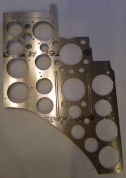
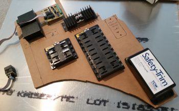
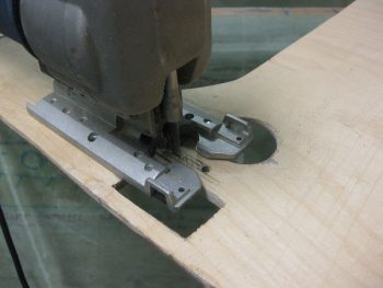
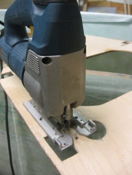
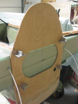
After getting the prop extension configuration settled with Sam, I then spent a few hours cleaning up the lightening holes by hand.  I also figured out where my #12 mounting holes for the Triparagon screws will be placed.  After figuring out the mounting screw locations I drilled the mounting holes and then countersunk the screw holes.

Cleaned up R side Triparagon

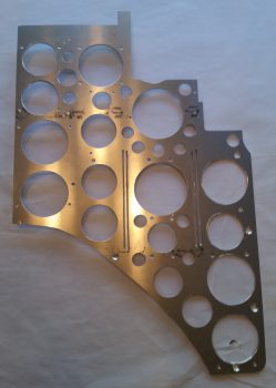
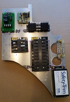
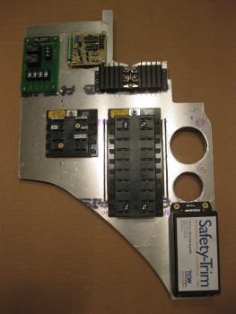
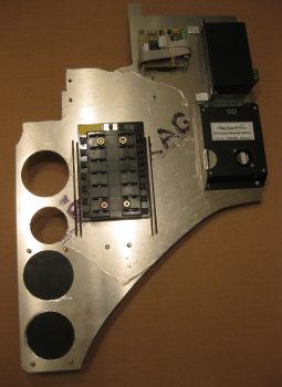
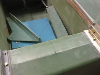
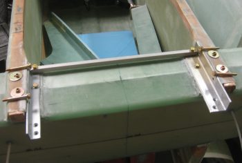
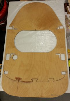
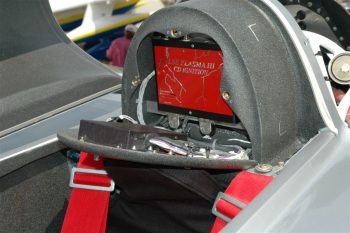
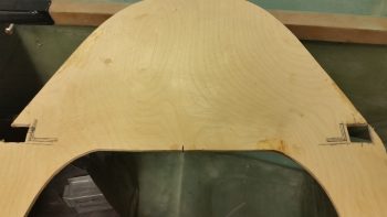
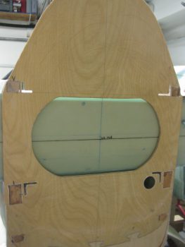
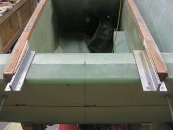
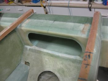
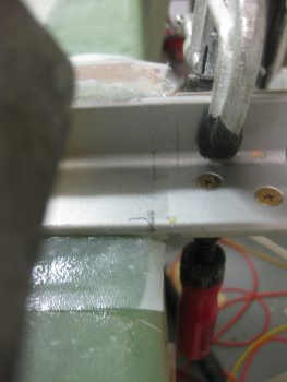
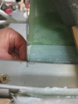
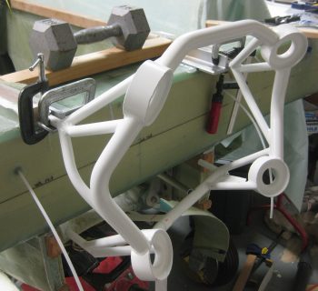
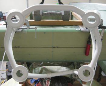
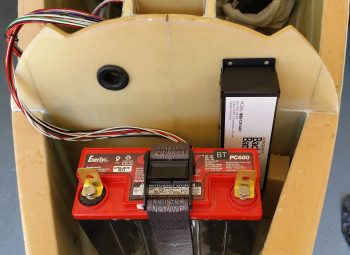
Here you can see the left side of the Triparagon with the cleaned up lightening holes.

Cleaned up L side Triparagon

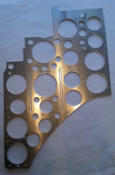
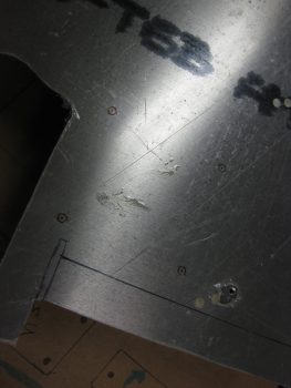
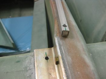
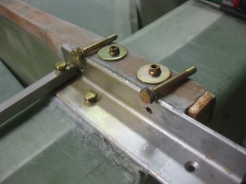
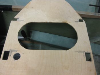
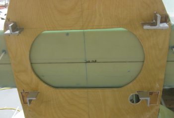
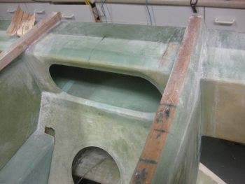
You may have noted that there are a some visible gouges on the edge of a couple of the lightening holes.  This is directly attributable to the new style cordless drill batteries in that they twice the batteries seemed to have died while I was drilling and as I was removing the hole saw bit from the lightening holes, the drill surged again causing these edge gouging.  Obviously I’m not happy about these unsightly marks, but it doesn’t change the functionality of the Triparagon, it just slightly diminishes its appearance and thus knocks down my cool points tally a bit!

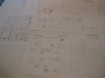
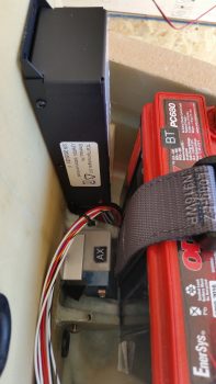
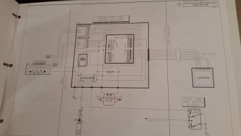
After cleaning up the Triparagon lightening holes I then worked for about 3 hours on redesigning my electrical system by removing the relay that controlled the circuit between the battery buss and E-buss as per the recommendation of Bob Nuckolls.  Technically, I repurposed that relay to be used as the heated pitot tube control relay with a net result of one less relay in the system.  I then updated the main electrical system diagram & the grounding buss matrix list.


Chapter 22 – Making Swiss Cheese

I started off today by mounting the main panel ground buss (G4), or “Forrest of Tabs” if you will, on the right side of the Triparagon.

Triparagon - Right side

On the left side I mounted the avionics ground buss (G5), and the bridge rectifier used for the Trio auto trim system.

Triparagon - Left side

Here’s a closer view of the components on the upper aft side of the Triparagon.

Triparagon - Left side

After mounting all the electrical components to dial in their configuration & spacing, I then pulled off all the components to commence drilling the lightening holes.  Which I did, spending the next couple of hours drilling the lightening holes.

Triparagon - Swiss cheesed

I’ll note again that after I initially cut out the Triparagon vertical from a panel of 0.09″ 6061T6 Aluminum it weighed just over 1.38 lbs.  After drilling all the lightening holes the Triparagon weighed in at 0.71 lb, so almost half of the original weight.  I expect that when all is said & done, the installed Triparagon structure with the top cross plate and support struts, will weigh in at just over a pound.


Chapter 22 – It’s Alive!

My Triparagon that is… or at least I can say it’s getting much closer.

Today I did a fair amount of physical work on the Triparagon, but what’s not seen is the even more work I did in figuring out optimized electrical component locations, hardware requirements, etc.  I also took a quick trip down to the Aviation Dept. at our favorite Orange & Blue big box stores to pick up a few stainless steel screws, etc.

I started out on the Triparagon by positioning and then drilling the 4 mounting holes for the two AG6 Warning Annunciators that I’ll be using.  The pic below actually shows the Triparagon upside down.  I’ll be mounting the AG6 Annunciator boards back-to-back, one on each side of the Triparagon, with a long #6 screw attaching one side to the other at each corner of the AG6 board.  Also, although not shown here, immediately following my drilling of the marked mounting holes in pic below, I drilled a fairly large lightening hole in the Triparagon plate immediately underneath/between the two AG6 Annunciator boards.

Triparagon AG6 Warning Annunciator mount holes

As for the right side Triparagon, besides the AG6 Annunciator board I also mounted the Schottky Diode with its heat sink, and the X-Bus (just to the left of the Main buss in the pic below).  As you can see I also drilled 2 more large lightening holes just above the Safety Trim box.

Immediately after I cut the Triparagon to shape, I weighed the panel at 1.38 lbs.  After the 3 total lightening holes that I drilled out today, it’s weighing in at about 1.15 lbs.  My goal is to get the Triparagon’s vertical plate weight down to about 0.6 lbs, with a total weight at under 1 pound.

Triparagon right side

On the left side I added the twin AG6 warning annunciator, as well as the E-Bus that shares the two top bolts for mounting with the Main Buss on the right side.  In addition, I mounted the Flight Data Systems’ GD-40 Carbon Monoxide Detector.  I’d like to point out that although the CO detector may look a bit bulky in the pic, it’s actually very light and only weighs a few ounces.  Today actually marks a pretty cool milestone considering that all my busses are in place and ready to be wired up & installed with the Triparagon into the plane!

You may have noticed a couple of slots that I “machined” (Ha!  That translates to “Skil Saw”) along each side of the Main Bus, and thus on each side of the E-Bus.  These slots are nothing more than wire management slots that will allow me to secure the wires to the Triparagon with either zip ties or cable lace.  They are clearly in a very rough state, as is the entire Triparagon actually, and will be cleaned up later.

Triparagon left side

Obviously I’m trying to get the majority of electrical components mounted to the Triparagon, which then allows me to determine hardware, space, wiring, and connector requirements now so that I’ll have as much of it as possible on hand for when I hard mount the Triparagon into the front of the plane.  I’m thinking one more good day on this baby, then on to working on the wheel pants.  I should also point out that once the Triparagon meets my design & operational requirements, I’ll mount it into the fuselage directly behind the F22 center post with around 6 each K1000-3 nutplate assembly hardpoints.  The nutplate hardpoints will allow me to remove and install the Triparagon whenever I need to during the build, and of course after the build as well!


Chapter 14 – Upper Extrusions

I spent a good majority of yesterday studying to get back into the groove for an Instrument flying lesson I had this morning.  Me and my new instructor flew south out of the SFRA, did a couple of holds off of Stafford before flying an approach and practice missed approach at Stafford.  If felt good to be back flying, even if it is training.  But enough about that . . .

Today I started off by shipping my 8″ prop extension back to Sam at Saber Manufacturing so he can drill the holes & insert the required 3/8″ bushings (in-between the 1/2″ holes I currently have) in order for me to mount the Silver Bullet prop.  Of course, originally, I had planned on going with a 3-bladed Catto prop which required 1/2″ prop bolts as per Craig Catto.  In addition, Sam will swap out my 1/2″ prop bolts for 3/8″ ones and swap out the crush plate with one that has 3/8″ holes.  It’s never-ending on these adjustments, eh?!  One change is never without its 2nd, 3rd and 4th order affects!

I then finalized the dimensions of my cardboard Triparagon template and then traced it out onto my 0.090″ thick sheet of 6061T6 Aluminum (the same sheet that I used for my gear heat shields).  I didn’t get the Triparagon cut out tonight, but will do so within the next day or two.

Marking Triparagon sheet aluminum

What I did get cut tonight was the 1/2″ x 1/2″ square 6061T6 Aluminum tube that I’m using in lieu of the plan’s GIB upper seatbelt mounts.  This tube will allow the upper seatbelt straps –with the webbing merely wrapped around it– to slide inboard and outboard to allow the GIB to have a much better variance in adjusting the upper seatbelt straps to their comfort.

I started the process of drilling the holes for the seatbelt tube by marking the extrusions on each side with lines that extended beyond the sides and edges of the square tube.

6061T6 square GIB seat belt tube clamped in place

I then carried those lines back onto the top of each end of the tube to mark the center point for drilling on each side.  I finalized trimming 3/8″ x 3/8″ square 2024T3 inserts, each about 1.25″ long, that slide into place on each end of the tube with the outside face of the inserts close to flush on the each side.

Left side GIB seat belt tube marked for drilling


Right side GIB seat belt tube marked for drilling

I started with a small drill bit about 1/16″ thick and then stepped my way up until I had a 1/4″ hole drilled down through the seatbelt crosstube ends into the extrusions and then through the Spruce hardpoints embedded in the CS spar, respectively of course.

Left & Right forward 1/4" holes drilled

Here’s a closer shot showing the forward bolt hole on the right extrusion very close to the same spot as my original mark.  Up on the longeron is the end of the GIB seatbelt cross tube with the 1/4″ bolt hole drilled through it as well.  In this pic you can see the 2024 insert in place (very snugly) in the end of the tube.  I’ll remove the inserts and Alodine them before re-inserting them before the final mounting of the seatbelt cross tube.

Right side 1/4" holes drilled

With the GIB seatbelt cross bar mod and the fact that my longerons are wider in the back than stock, it took me a good 20 minutes to figure out the best length of AN4 bolts to use in all but the aft horizontal bolt position on the extrusions (which is the stock plans size bolt obviously).

Upper engine mount extrusion bolt selection

Here’s another shot of the bolts that will get mounted into the upper right engine mount extrusion, right longeron, and CS spar hardpoint.

Right upper engine mount extrusion bolts

Here’s a shot of the all the upper extrusion mounting hardware.  As you can see, I also put the firewall back in place.

Upper engine mount extrusion bolts

I then did a quick check to see how my GIB headrest / component shroud fit & looked (maybe I’ll start calling it something a bit catchier like, “the vault” or something).

GIB upper seatbelt strap crossbar & component shroud

It fit fairly well.  Of course some minor tweaking will be in order, but so far I’m happy with the configuration back here with the D-Deck and all.

GIB upper seatbelt strap crossbar & component shroud

Tomorrow I’ll continue to work getting the extrusion mounting bolts installed.  First, I’ll prep the holes in the wood using epoxy with a little bit of alcohol added to it as per the latest CSA newsletter (Oct 16).  I’ll also work on the GIB seatbelt upper strap bar and try to get the Triparagon cut out and maybe work on that a bit.  As soon as I get the bolts installed and the seatbelt cross tube finished, I’ll then finally start back on the wheel pants before rolling into the nose and canopy builds.


Chapter 4/14/22 – Firewall & Electrical

Today was another light build day since I went to a Fall Fun Festival with some friends.  I did get a bit done, starting off with some of what I worked a little bit on yesterday, then finished up quite a bit today: my “Triparagon”.  Or, basically the big motherboard for the vast majority of all my electrical system components: busses, grounding blocks, etc.

Since I now know exactly how my canard controls fit into the forward fuselage/nose, I was able to tweak the size & dimensions of the vertical Triparagon plate.  I recut another fresh, updated cardboard mockup and then set about figuring out the placement of my electrical components.  I’m extremely pleased with the fact that I’ll easily fit virtually my ENTIRE electrical system on this one plate.  And the only reason I say “virtually” is due to any future potentiality that I may have a component that doesn’t fit on the Triparagon, but currently EVERY piece of the electrical system fits on it!

Triparagon

I then spent a good half hour between removing the peel ply off the firewall front face 1-ply BID layup and then razor trimming the edges.  The firewall looks good and is very close to getting  mounted.  I do have to do some minor sanding along the edges and a couple places on the front face, and quite a bit on the aft side since I didn’t peel ply it for some odd reason (that was back in 2011, so my memory is foggy on why I didn’t peel ply it! . . . )

Firewall - forward side BID

I then spent another good 45 minutes looking at the configuration of stuff on my D-Deck area.  The 1/2″ square 6061T6 bar that you see will traverse across the fop front side of the CS spar, attached at the front corners of the top engine mount extrusions.  Yes, this is a modification of the GIB seatbelt mounts and is NOT per plans.  This bar will be mounted with the AN4 1/4″ extrusion bolt on each end (with 2024 inserts inside each of the bar for strength) and also have center mount countersunk screws to keep it secure.  That will allow the GIB to simply slide the upper seat belt shoulder straps inboard or outboard for comfort.  I weighed all these components, and this modification is within an ounce (probably less) weight-wise as the plans configuration.

The black GIB headrest and components shroud cardboard mockup (that I made in Germany) is a modification I’m doing ala Wayne Blackler (see second below).  I like this configuration INFINITELY better than the plans shroud that has the GIB with their essentially in coffin or something…. Blech!  With my GIB upper seatbelt bar mod I did have to trim the depth by about 3/4″, but it still looks as if everything I had planned to get mounted inside the headrest will still fit comfortably.

D-Deck GIB headrest

Wayne’s GIB headrest and component housing:

Wayne Blackler's GIB Headrest

The next couple of days I have an out of town visitor coming in, so between football, cooking out, visiting, beer drinking, etc. not a whole lot of work will get done.  Plus, I’ll be prepping to get back into my flying lessons which start this Wednesday.  Of course I’ll still be working on the build, but it will be significantly less with all the flying I’ll be doing!


Chapter 14/23 – Engine Mount

I started off today with something I was curious about, and that had nothing to do with the engine mount.  I really just wanted to see where a good location was for the fuel pump, and in relation to the fuel valve.  I played around with a few different locations, stopped at this one since I really like that the pump can be mounted vertically here, thus driving as much of the pump weight forward as practically possible.   It also gives some nice space to the fuel valve.

Fuel pump & valve mockup

I then moved on to measuring the top engine mount posts to take 0.32″ off the end of each side.

Trimming upper engine mount stems

Here is one of the posts after I trimmed it 0.32″.

Upper engine mount stems trimmed

I then started marking up the firewall to cut the slots so each engine mount extrusion could transit the firewall.

Marking engine extrusion passthroughs

Here’s a shot with both upper and lower engine mount extrusion slots shown marked for cutting.

Extrusion pass-throughs marked

I started each extrusion slot by drilling a few 1/8″ holes for the top extrusion slots and 3/16″ holes for the bottom extrusion pass-through slots.  I then transitioned to using a saber saw to finish cutting the holes.

Cutting extrusion pass-throughs

After finishing each hole with the saber saw, I then sanded down the pass throughs with 32 grit paper.

Cutting extrusion pass-throughs

Here’s a shot of the firewall mounted with all the engine mount extrusions pass-through slots cut.

Engine extrusion pass-throughs

I then set the engine mount extrusions in place to see how they looked & fit.

Engine mount extrusions in firewall

Here’s a closer shot of the engine mount extrusions.

Engine mount extrusions in firewall

I then tested out my trimmed engine mount by clamping it in place on the upper engine mount extrusions.

Mocking up engine extrusions & mount

Again, here’s a closeup shot of the upper right extrusion.

Engine mount closeup

Ahh, trimming the top engine mount posts did the trick.  Now I can dial in the upper engine mount rings to FS 134.2 as per plans.

Top engine mount at FS 134.2!

I then pulled the firewall off and mocked up just the upper engine mount extrusions before I glassed them in place.

Mocking up upper extrusions

After verifying that the extrusion spacing was good, I then went to town sanding the areas that will get glass during the mounting of the engine mount extrusions.

Sanding in prep for glass

I then vacuumed up all the sanding dust.

Prepped for glass

I have to say that this is quite a detailed layup.  The time lapse between the pic above and below is over 4 hours.  Regardless, here are a couple of shots with the upper engine mounts glassed & floxed into place.

Upper extrusions glassed/floxed in placeUpper extrusions glassed/floxed in place

And a shot from the aft side , , ,

Upper extrusions glassed/floxed in place

I then verified that the left side extrusion’s firewall alignment mark was good, which it wasn’t.  So I spent a few minutes tweaking both side, then once I got them straight, I snapped this shot.  The line at the top equates to the forward side of the firewall, while the bottom line equates to the aft side of the firewall…  Thuss why I paid so much attention to getting these marks aligned properly.

Left extrusion firewall hash marks

Here’s the right side extrusion firewall alignment mark.  Due to the angle of the camera, the extrusion and the spar, it looks a bit off.

Right extrusion firewall hash marks

But if you look at it from this angle, it’s spot on.

Left extrusion firewall hash marks

Wth my upper ending mounts aligned properly, I then wanted to better align the bottom engine mount rings.  You’ll note in the pic of the plans below, the upper engine mount ring ends at FS 134.2, while the bottom engine mount ring ends at FS 134.45… 1/4″ aft of the upper engine mount ring.

Engine mount fuselage stations

I used my level and a 1/4″ block of aluminum to check the lower engine mount rings for the proper fuselage station.  They were just a bit aft on the bottom side, but a slight push forward got them to the proper fuselage station.

I strapped the bottom of the engine mount to the center of the landing gear to create just a slight bit of pressure, which got the lower engine mount rings to the correct fuselage station.  Since the epoxy will still a bit pliable and not cured yet (I used slow hardener for this layup), this should set up the correct fuselage stations for the top & bottom of the engine mount.  At a minimum, it will get the engine mount rings very close to the required FS settings so as to minimize stress when the mount gets bolted into place.

Lower side mount strapped for FS 134.45

Here’s a shot of the aft end of the fuselage with the engine mount being used to ensure the upper engine mount extrusions are set in their correct positions.

Lower side mount strapped for FS 134.45

Tomorrow I’ll clean up this layup and then continue to press on to get the engine mount ready for install.  I’m not sure if I’ll tackle the lower extrusions yet since I’ll have to assess the pros & cons of flipping the fuselage or using Cab-O-Sil and simply working the layups upside down.


Chapter 22 – Updated/new Wiring Diagrams

Today I spent the first half of the day getting a safety inspection done on my motorcycle. Just as they were finishing up the inspection it started to drizzle, which then turned into a fairly steady light rain for most of the day.  Which of course meant not getting the garage organized since most of the stuff has to come out so that I move & reorg the stuff inside.  Oh, well.

So, after the inspection was complete I did a fair amount of research on the heating system.  That rolled into updating a few wiring diagrams to reflect the updated electrical requirements, which included: the removal of the GIB Infinity control stick, resulting in the need to update the switch diagram, and of course updating the newly created Heating System diagram (these 3 are shown below).

Updated/new wiring diagrams

I then went down to the shop and finally cut the 1″ x 1″ Chromoly steel engine mount square tube extrusion into 2 “L”-shaped angled pieces. I know some may question exactly why I’m throwing in only one mount of 4130 steel.  Well, I was actually going to install 2 4130 steel mounts catty-corner from each other, but when the bottom mounts required the use of 3/16″ angled extrusions, I simply decided that between the weight and cost of buying more/thicker 4130 steel, I would punt and simply put only the one top side in.  Yes, I considered both top engine mount extrusions being 4130, but now with my engine weighing in heavier, I’m going to employ a little Operational Risk Management here and just go with the one side to keep the weight down, and to keep from having to buy more metal!  A little odd?  Perhaps.  But I’m going to be a little eccentric and go with this!

By the way, after I got it all cut, I matched it up to the engine mount and it was a good match!

1" x 1" 4130 Chromoly engine mount

Ok, perhaps tomorrow I’ll actually get around to reorganizing the shop in order to be able to move around and build in it!


Chapter 23 – Silver Bullet Ordered!

I’m still in the throes of researching, documenting and integrating the ton of info I acquired at RR.  I’ve spent a fair amount of time on the phone, collectively, with Gary Hertzler regarding the prop, Sam from Saber Manufacturing regarding the prop extension, and my engine guy, Tom Schweitz, from Aero Engines in Winchester, VA regarding my engine.  It was good to reconnect with Tom after over a year having talked with him last since not only did I get some refined engine specs for Gary so he could build my Silver Bullet, but things have changed A LOT in the aircraft engine world . . . e.g. ECi no longer exists since Continental bought them out!.

[One quick note on ECi: since ECi no longer exists, Continental is apparently not overly concerned about hawking it’s wares to the experimental market.  Tom noted that if I have an issue in the future with ONE of my tapered-finned cylinder jugs –an ECi exclusive product– that I could quite possibly have to buy FOUR new jugs since the tapered-fins are no longer in production!  He has a set of 4 new certificated ECi Nickle+Carbide cylinder jugs that he’ll swap out mine for free… well, actually the cost is about 8 pounds added back on my engine!]

Ok, the good news is that I got all the info I needed for Gary and the proverbial informational cats were herded & coordinations made with all the players concerned regarding the prop.  The bottom line is that I got my order form filled out and sent off to Gary!  So within the next couple of months I should be the proud owner of a Hertzler Silver Bullet prop!

Marco's Silver BulletNate Mullins' Silver Bullet

I tried to find a stock photo, but couldn’t so here’s a couple shots of Silver Bullet props on my buddy Marco’s plane…


. . . and on Nate Mullins’ Long-EZ:


Besides working to get the prop ordered, I’ve also been working on an ACS order, a McMaster-Carr order and I just saw an email where Wicks Aircraft is having free shipping tomorrow on any order over $100.  I’m trying to finalize a few more pieces of 4130 and aluminum that I need, so I was figuring those out before submitting those respective orders.

One piece of aluminum in specific was for the GIB control stick.  I made a huge design departure on my aircraft where the GIB stick is concerned, which I’m very grateful that I made the discovery on how exactly it works back there.  Why the change?  Well, after spending a considerable amount of time in the back seat of Marco’s Long-EZ, I realize that during any period of heavy control usage: takeoffs, landings, pattern work, etc. that I have to move my right leg over to one side ESPECIALLY if the stick is mounted (his is removable).

When I queried the old guard on this, including Terry Lamp, the builder of Marco’s bird, they all said to make the stick removable!  It’s interesting how it takes a bit to reset our own paradigms, since mine in this area had always been to have the back seat control stick hard mounted.  Somewhat of an instant replacement (as JD sells it!  Good job JD! ha!) in case the front stick has issues.  After the flight back to Chesapeake from RR, I concluded that the only real logical thing to do was in fact make the GIB control stick removable.  With the design of the right side arm rest and the engineered plans version of the flight control system, there’s no viable way of getting around NOT having a permanently mounting control stick if you want to save the GIB’s thigh from being pummeled black & blue during any maneuvering flight.  Ok, big breath, big sigh … AND decision made to not hard mount the aft Infinity Control Stick!  In fact, it stays at home as an extra stick and instead a simple, lightweight, removable stick gets put in its place …

something like this:

New removable GIB stick

I dug out the control stick that I bought from the Cozy Girrrls, measured the OD at 0.617″ and then found some spare 2024 tubing stock that fit it.  The ID of this stock is 0.634″ and the OD is 3/4″.  I had some spare foam handle grips that I got from McMaster-Carr, so I threw one of those on the end.  Wow! It fit and felt perfect!  Done!  For final measure, I took a plastic cable channel insert that fit into the end & slid that sucker into place.  I can always swap that out, but for now –once I cut the tubing to length– I’m calling the GIB control stick COMPLETE!

Tomorrow I plan on getting the shop organized, taking into account the CS spar now mounted permanently on the fuselage… yes, that beast takes up some space!  Then I’ll continue for another few days to work these odd ‘n items before getting back to finalizing the canard & elevator install.


Chapter 23 – Prop Selection, etc.

When I got back from Marco’s place in Virginia Beach last night, I pretty much just decompressed from a very busy past couple of weeks.

Today was mainly about getting organized for the upcoming build.  I had a myriad of items on my list from RR that I wanted to capture (read: not lose!) & filed away in the right spots so that I could find them again.

I started out today like I do many build days by going down and grabbing breakfast just down the street from me.  While there, I wrote out my task list focusing on the myriad of the “little things” that need to get done.  I want to spend a few days to a week getting some of these ‘minnows’ knocked out before heading on to the big fish.

After I got back to the house, I spent a good hour updating my parts tracking spreadsheet, and tweaking my upcoming ACS order.  I did a good 45 min more of research on CAMLOCs and CLOCs (Skybolt) to figure out what specific parts I need and also refine my 1/4-turn fastener requirements for the entire airplane.

I mentioned in my project update that while at RR, between polling builders & fliers on their prop choice, flying in front of the Silver Bullet first hand in Marco’s Long-EZ, and having a quick discussion with Gary Hertzler, I made a final decision to go with the Silver Bullet prop over the Catto 3-bladed prop.  I will admit that with so many folks happy with their Silver Bullet props, that I can’t see (or justify) spending almost $2,000 more for a Catto prop when the Silver Bullet gets such rave reviews.  And to be clear, this in no way diminishes my opinion of Catto props.

So, while out to take my truck to a service station for its annual safety inspection, I stopped at Lowe’s and picked up a Grade-8 7/16″ x 6″ bolt to use as a good estimate for comparing the weight of my current on-hand 1/2″ x 6.5″ prop bolts to the weight if I were to drop down to 7/16″ diameter prop bolts –which is what I hypothesized would be used for the Silver Bullet.  After some extrapolation to account for the 1/2″ shorter bolt, and weighing all the extraneous washers, etc., I concluded that using 7/16″ prop bolts vs 1/2″ bolts would save me 0.87 lb. … at the very aft end of my airplane.  That’s fairly significant considering weight & balance on these lighter birds.

Weighing 7/16" vs 1/2" prop bolts

Now, I did all this due to the fact that I had decided to go the 3-bladed Catto prop route a long time ago.  In fact, in a discussion with Craig Catto back in early 2013, he stated that with an IOX-340S engine I should be using 1/2″ bolts to mount one of his props. Thus, when I had Sam at Saber Manufacturing make my 8″ prop extension I had him configure it for 1/2″ prop bolts.

Jumping ahead to present day, with weight data in hand, I called Gary Hertzler to discuss using 1/2″ prop bolts with the Silver Bullet.  He said it could be done, but that the optimum size prop bolt would be 3/8″!  Wow, even smaller than I had estimated from my layman’s research.  Gary said to check with Sam since there was a good chance that Sam could merely redrill the smaller holes for 3/8″ bolts in-between the larger 1/2″ holes on the aft flange of my prop extension.  Well, sure enough Gary was right and Sam is wiling & very able to do exactly that.  And since I opened up the prop extension box for the first time since 2013 –with all the components new & unused– Sam will simply swap out all the 1/2″ bolts & components for the 3/8″ versions, including the crush plate.  With that, this completes all the prerequisite planning & coordination and means that I will pull the trigger here soon to become an official Silver Bullet slinging Canardian!

Moving on . . .

While at the RR Saturday evening Central States Association (CSA) meeting hosted by Terry Schubert and Nick Ugolini, I won the auction for one of Buly’s Oil Heat Pumps that I’ve been trying to get my hands on since I learned about them a year or two ago.  Luckily, I was able to get this thing WAY cheap and saved well over $100.  Just another plus for such an awesome RR!

Oil Pump for oil heat system

Last night I took the plunge and spent about 3 hours building my electrical diagram for the Oil Heat System in my bird.  I still have some more research to do since specifics on this system are vague at best.  After a good discussion with Greg Norman at RR, I’ve reached out to him to get some specifics on his install since he also has this oil pump.  Here in the near future I’ll discuss with Buly as well to finalize the architecture.  Of course, I’ll be performing a fair number of tests as well to ensure the circuitry is good before this system actually gets installed.

One final important point to note from RR.  I had a good discussion with Mike Toomey on wheel pants.  He gave me a number of tips on how I could continue with my install now, but by minimizing the actual tire cutouts on the bottom of the wheel pants I could then do a final configure on the pants after my 40 hours are flown off and simply widen the pant holes for the wheels in relation to the wheels after I do any mods.  With the advice I got from Mike in my back pocket, I’ll be moving forward with a near-total install of the wheel pants after I get the low-hanging fruit task list knocked out and the canard & elevator install finished.

Ok, back to work!


Chapter 9 – Wheel Pants . . . etc!

Today I started out by refining my wheel pants prep & wing mounting to CS spar plans.

I then discovered that my UPS friends had delivered my ACS order, and yet another Mouser order. I logged my new parts in my spreadsheet, sorting through the myriad of CAMLOC bits ‘n pieces & more new panel switches.  I identified all the switches, labeled each one, and stowed them away with all the other switches.

One new item of note that I received today is the TCW Technologies 3-Amp hour Integrated Backup Battery System (IBBS).  After W&B discussions with Marco regarding his new Long-EZ, he had advised me to literally front load as much component weight possible into the nose region of my plane to favorable counter the sensitive rearward balance tendency of Long-EZ’s.

As I mentioned in a previous post, I had originally planned to install a 3AH model IBBS since it would serve me well enough –and for the specific reason that I would be saving weight over the 6AH model.  So upon the “load the front heavy” advice I received from Marco, I assessed putting in the bigger model.  Ah, but alas, the 6AH model was physically too big to mount it where I had planned (see pic below) so I went with my original plan and pulled the trigger on the 3AH IBBS.

Testing IBBS fit

As you can see in these pics, the 3AH IBBS fits perfectly… and according to plan!

Testing IBBS fit

After getting all the first half of the day’s miscellaneous tasks out of the way, I started in on something I’ve been trying to knock out over the past few days.  You see, Marco has been diligently working on the pitot tube wiring system for our Long-EZs, and I haven’t been the best teammate in assisting with the effort (See Marco’s latest post regarding the pitot tube electronics on his blog).  Moreover, a number of days ago Marco asked if I could draft up the wiring diagram (#24) for the Heated Pitot Tube Electronics.  Thus, a main goal I had today was to get this sucker knocked out, which I did below.  Of course there will be a bunch more mods to this diagram as we move forward, but as of right now we have a good baseline schematic for the pitot tube electronics!

Pitot Tube Electrical Diagram

After completing the heated pitot tube wiring diagram, I then went down to the shop to get some work in on the wheel pants.  My current issue is one that many builders seem to be confronted with, but oddly enough I’m starting to see a possible nascent trend that only 400×5 tire users seem to be afflicted by ? . . . and that is that until some type of slots are cut into the bottom of the wheel pants for the tires, the front and back half of the wheel pants can’t be mated together.  Nate Mullins certainly had this issue.

As it goes during many a times during this build it was time to take yet another leap of faith and cut into the bottom of the wheel pants.  Of course I don’t know exactly where the wheel will reside in each wheel pant, which prompted me to look at a myriad of pics from other builders’ installs.  I decided to shoot for center mass: 4″ forward on the front side of the wheel pants and 3.3″ aft from the front edge of the aft side wheel pants.

Since I would destroy the bottom CL mark by removing the glass on which it resides, I decided to move the CL marks out of the lines of fire on all the wheel pant parts.  I grabbed my tape and a plumb bob line and ran the line down the CL of the wheel pant… Uh, except maybe I should aim for the correct side of the wheel pant! (I started on the top of the wheel pant in the pic below, but luckily I caught my error!)

Marking top (wrong side!) centerline

Ok, the BOTTOM of the wheel pants… this is much better!

Marking bottom (right side!) centerline

I then marked the aft edge of the front side of the wheel pants for certain destruction and mayhem!  Hoo-ah!

Bottom front wheel pants marked for cutting

I then extended the centerline mark rearward on the aft wheel pant pieces as well.

Finding aft bottom centerline

And marked out the areas of certain destruction on these as well!

Aft wheel pants marked for cutting

After cutting out the notches in each side of the wheel pants, I still couldn’t get the aft flanges into the front side receivers!  I ended having to extend the notches another 1/2″ forward and aft, respectively, into the wheel pant assemblies.

Voila! It finally worked [BARELY] and after a fair bit of wrangling –and 3-1/2 years!– I finally was able to mount the back part of the wheel pants into the forward assemblies for the first time ever!  And I bought these suckers from Sam James back in January 2013.

Wheel pants wheel starter holes

Here’s the first shot of my wheel pants assembled into one single unit per side! However, the fit is still really tight so the first order of business tomorrow is to give the flanges and receiver mating surfaces another intense round of sanding.

1st time wheel pants assembled!

Excited to see actual, assembled wheel pants, I set them next to the gear strut for a quick mockup just to get a feel for the general size and shape.

Quick wheel pant mockup

Another shot of my quick wheel pant mockup.

Quick wheel pant mockup

Now that I know the wheel pants actually mate together (and that none of the vertical or horizontal centerline marks are off by more than 0.1″), I’m really happy and confident that the wheel pants should mount & fit nicely over the wheels and onto the gear struts!