Chapter 22 – Upon further review…

As I mentioned yesterday, today was not only all about planning, but probably even more so about research.

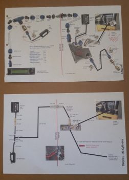
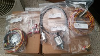
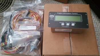
Yes, I went down a few rabbit “trails” lets call them, since they weren’t overly exhaustive on time, to verify some of my checklist item entries in regards to the specific equipment I’m using.  For example, I’m using the SilverHawk Fuel Injection servo, so I pulled the manual out on that to see how it states the engine starting sequence should be conducted.  I also bounced the book answer off what my notes said from many pilots who are flying this fuel injection system in the real world.

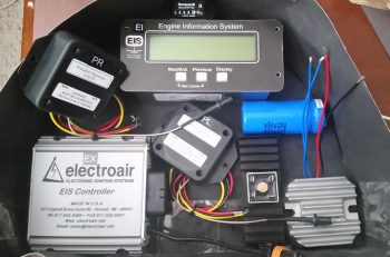
Some of my research found updated manuals that now require a different installation configuration that what I had originally had identified.  The example here would be the ElectroAir (“Jeff Rose” or “SDS” style) electronic ignition.   When I first started the manual stated to use either a fuse or a circuit breaker.  However, the latest manual version states explicitly to use circuit breakers.  Not a big deal (always a bit more $$ though), but my wiring diagrams depict these circuits using fuses.  Thus, I fired off an email to ElectroAir to confirm this info, and included another couple of questions on starting procedures as well.

Alas, I did spend a couple more hours tweaking the HXr-based checklists.  Working on the HXr these few hours over the last couple of days has also given me a much better feel for the switchology and flow of this EFIS.  In fact, so much so that it drove me to make some decisions to remove a remote switch control that I originally put in place when I was considering the older HX EFIS, and/or also an HXr that was non-touchscreen.  The switch function I removed was the HXr Page Flip function.  In addition, I have some ideas on what to backfill the open positions on my throttle handle 5-position castle switch, but will need some time to research those out as well.

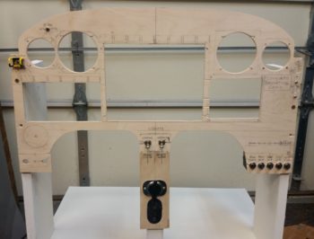
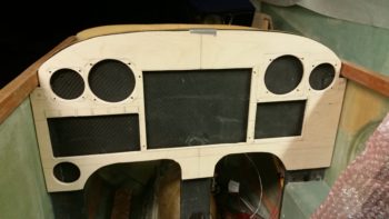
These mini-mods on my system is exactly why I wanted to get the panel mocked up outside the airplane. which then allows me to work it through a shakedown cruise of sorts to better refine component/switch placement and cockpit management long before the panel is ever mounted into the actual cockpit.  With each new install of a planned component, switch or software feature, it really does flush out these integration issues and often drives some minor changes for a much better operational flow.

I’m very much a believer in task efficiency in the cockpit to minimize what could really be classified as burdensome or unnecessary processes if we take a hard honest look at them. To be really honest, when I see a question asked on how make a cockpit task much simpler, with an old skool response of just mask the deficiency by adding it the checklist (because ALL pilots follow the checklist!… it would be sacrilegious not to!), I find it a lazy response and it personally disgusts me.  Cobble a number of these laissez faire implemented processes together, and I’ll give you a needlessly task-saturated pilot who is spending more time reading a uselessly bloated checklist and not doing what he should be: flying his plane.  Am I wrong?  Sadly, I would say that many NTSB reports will show that I’m not.  So… I’ve had a lot of very in-depth discussions on this topic with a lot of builders & pilots, specifically Marco and Dave B.  I consider myself fortunate in that these discussions and collaborations often highlight areas that I have been able to optimize even further.

As for my task planning, honestly I’m a bit further behind then I wanted to be on that.  I was planning to have it knocked out during my time away, and did scrub a couple old task/goal lists that I have, but the new one is still in its nascent stage.  I do plan on getting that done tomorrow, but I will get some shop time in as well!


Chapter 23/24 – Throttle Quadrant & Armrest

Today I started out by removing the peel ply from the cured throttle quadrant mounting hardpoint layups and then cleaned it all up.  I then drilled the holes into each of the 4 hard points, removed the protective plastic wrap I had stuffed into each one to keep the nasty stuff out, and then cleaned up each hole to allow me to test mount the throttle quadrant.

I have to say it all looks good and I’m very pleased with the position of the throttle quadrant.

Today was more of an R&D day than it was a build day, as there was a lot of configuration stuff to figure out for not only the immediate throttle quadrant area, but the entire left armrest console. For example, when I placed the left armrest vertical wall in place, I immediately noticed that it “fanned” out in a way towards the aft end since the armrest wall was basically parallel with the centerline of the airplane.  This makes the side wall look as if it’s fanning out too, because in reality, well, it is since the fuselage gets wider at the pilot seat bulkhead.  This is probably even more pronounced on my plane since I have a more football shaped fuselage than do most Long-EZs.

I also needed to see how the seating space was affected in the pilot’s seat by this “fanned” out left armrest sidewall.  Interestingly enough, I had plenty of room either way as I wasn’t really pressed against either one.  I sat in the pilot’s seat a good 45 minutes simply taking notes and getting a good feel for how the ergonomics of possible configurations would work.  I will add though that the past few days, being able to actually sit in the cockpit and process ideas based on real dimensional data, have been invaluable.

Before I could decide to kick the aft end of the left armrest vertical wall outboard or not, I needed to know if the aft end would still allow me to mount the fire extinguisher in it since I really don’t see anywhere else to mount it . . . and keep it accessible in case of emergency [Side note: I’ve seen so many canard aircraft with fire extinguishers that are truly only accessible on the ground… not good in my book!]

So I drug out the fire extinguisher and low and behold, if I kicked the aft end of the left armrest wall outboard about a 0.25″ (e.g. narrowing) it will still allow me to slide the fire extinguisher in there . . . with a caveat: I’ll have to glass the aft end of the left armrest vertical upright with the inside glass laying up glass-to-glass with the glass on the exterior of the armrest console.  No big deal of course, just a bit more work.

With data in hand, I decided to go with the narrower, albeit straight, armrest configuration. So I was about ready to glass the top and side of the left armrest together and then the ancillary stuff, but honestly the armrest was the easier layup so I went ahead and knocked out the more difficult ones first: the glass sleeve (tube) that the fire extinguisher will get mounted into (on the left, pic below) since I won’t be using the included metal bracket; and the cup holder that I plan on installing just forward of the throttle quadrant.

Interestingly, I needed the ID of the cupholder to be 2.9″ and the only thing I could find that could be used as a mold (without making one from foam) was a small household fire extinguisher that I pulled out of my other house when I sold it (shown on right, pic below).

A point of note on these: due to the fact that I have a TON of leftover UNI from previous layups, I used it for the majority of glass in these 2 layups.

Tomorrow I plan to glass the left armrest top to the left armrest sidewall as the first thing on the build agenda.  Then while that is curing, I’ll pull the peel ply and clean & shape these 2 layups I did tonight.  I also plan on continuing in my quest to finish the left pilot armrest console so that I can press forward with the few GIB area and nose area items, including finalizing the install of the heat & air system.  This of course will be facilitated by my being able to install the 3 heat/air control cables into the left armrest.


Chapter 22/24 – If it pleases the panel

I started off today by pulling the peel ply off of the 7-ply bracket stock, and in turned pulled the bracket stock off of the taped-up 4130 1×1″ square tubing form.  As you can see, it came out just fine.  I just need to sand the inside, trim it up and cut it into individual brackets.

Here’s an end view shot of the 7-ply bracket stock.  Note the CAMLOC that I’ll be using the bracket stock to install.

I had to run some errands, including returning a motorcycle trailer I borrowed from a friend of mine… that took quite a few hours.  When I returned, I essentially spent the rest of the evening figuring out tweaking the component locations on the mockup instrument panel.  I think I’m really getting this panel dialed into where I want it!

I did have to make one major change so far: you can see in the lower left hand side where I filled the 2″ diameter heat vent hole back in by sanding down one of the 2-1/4″ instrument hole plugs that came out when I drilled the upper holes.  I then glued the new 2″ round plug back into place (I wanted to get this done so it would cure overnight).  The reason for doing this is that I decided the switches below the vent need to be higher for easier access, especially since the throttle handle will hinder easier access to that lower area just above the left armrest.

Tomorrow I’ll start back on the ELT mounting bracket and then probably do a lot more on this panel.  I want to get the panel to the point where I can get some serious wiring done in order to power up and check out all the instruments that I have on hand.


Chapter 22/24 – Ribs are done!

Today I started by . . . yep, adding the last bit of dry micro to the last 2-3″ middle area of each micro cap on the pilot thigh support ribs.  These things looked like twins with their shiny micro midsection glaring away, untouched and unspoiled by the thigh support top plate.  So, after sanding the middle micro areas on each each rib top dull, I then whipped up another round of dry micro and applied it.  All in all, I seriously only needed 1/8″ to 3/16″ more micro here, but man this is one of those things in the build that wants to be stubborn!

As the dry micro cured atop my ribs, I got to work finalizing the instrument cutouts for the mockup instrument panel that I’m constructing.  This panel will not only allow me to test instrument, avionic & component placement –and FIT!– but also put them all in their near-final position to allow me to wire them up.

After a few hours I finally saw what I’ve been looking for the last couple of days: no flat or untouched micro atop both my thigh support ribs… yeah!  I started cleaning them up by literally shaving the sides of the overhanging micro like you would a big block of cheese.

Once I got the sides close, I then switched to a sanding block to finalize the sanding of the added micro top.  I may add one more ply of BID just in the center areas for strength, but primarily to keep these from getting chipped away over the years.  Regardless, this part is DONE!

I then tested out the ELT location using the mounting bracket that was included in the ACK E-04 Retrofit kit (read: “starter” kit, IMO) that I just received today [perfect timing!]. The kit also included the panel mounted control head, so I’ll be mounting that in the mockup panel as well.

I also received the Eberhard latch that I’ll be using for the nose hatch.  This is close to the one I saw on Rick Hall’s Cozy IV at Rough River.  I added the wire clamp nut assembly making it pretty much ready for install [Note: I might take the drill to it and drill a few lightening holes since this thing is a bit heavy for its size].  Below the latch is in the hatch closed & locked position.

Here’s the Eberhard nose hatch latch in the hatch open position.

I also cut some uprights for the base of the mockup instrument panel.  I’m making this panel mounting stand a bit taller than just the main instrument panel area to allow for mounting the Triparagon behind the panel, since it plays such a key role in the panel instruments’ wire cross connections.  I went to dinner with my buddy Rob tonight, so before I left I spent about 15 min. painting this base with some white primer to hide all the unsightly water marks and wear on these “trash” pieces of wood that I used.

Tomorrow I plan on continuing with the seemingly unending saga of getting the pilot thigh support top plate installed.  My main task is to get some tabs glassed onto the lower aft side of the instrument panel to allow mounting 2 CAMLOC fasteners that will secure the front side of the seat support plate in place.  I’ll be working on the base for the ELT mounting bracket as well, shaping the fuselage floor to permanently install nutplates to secure the ELT bracket.


Chapter 22/24 – Pile the weight on!

I started out today spending well over an hour doing some research, answering questions, and providing info to Bob Nuckolls, et al. in response to a question I asked on the Aeroelectric Connection forum.  The question I asked was on how to create or modify a 4-into-1 video splitter to channel the micro cameras I’ll have on ship for viewing the back seat left & right fuel site gages, top side looking aft (at engine/prop), and bottom side looking aft (at engine/prop).  This device will then feed a GRT-integrated USB video module that will allow me view the video feeds in a small sub-window on my EFIS either auto- cycling through (that was one of my questions how) or by manual select.

I then got to work on round 2 of the pilot seat thigh support rib tops.  I took the profile of the bottom of the thigh support cover’s underside contour and then cut a cardboard template out so I had a good 1″ wide rib top edge profile to then cut the 1-ply prepregged BID tapes for each side of each rib.

Below you can see I’ve got the 1-ply layups + peel ply on the left rib (bottom) and on the side of the right rib, with the plastic still yet to be pulled.  I know I’ll have to add around 3/16″ -1/4″ more dry micro on top of the existing micro, so I laid up these edge plies of BID so they stuck up above the existing micro a bit.

Once the layups cured for about an hour, I then trimmed them a bit, cleaned them up and then added another round of micro.  I then of course had to add massive amounts of weight to the thigh support cover plate . . . Why?  Because I could …. (grin)

During my shop shenanigans I heard a delivery truck stop by.  A little while later I did in fact find a couple packages on my doorstep.  The first one was from Airflow Performance and had the 90° and 85° air intake elbows that I ordered, with the associated gaskets.

These elbows make up the physical mount and air intake for the air coming out the of Silver Hawk fuel injection servo into the Superior cold air plenum.  In the pic below, the nose of the aircraft would be to the left, prop to the right.  Since all the cold air induction plenums are built for forward facing engines, to incorporate one I had to get my air turned around.

To be clear, this isn’t something I did willy-nilly, although I know a number of Cozy builder/ drivers have done it with reportedly good success.  I conferred with Kevin Murray at Sky Dynamics, my IOX-340S engine builder, Tom Schweitz, and just within the last week I had a good discussion regarding getting this air turned around with Pete at Precision Airmotive, the maker of the Silver Hawk fuel injection system.

I’ve also been discussing this quite a bit with Chris Seats, a fellow Long-EZ builder.  While Chris is not using the Silver Hawk FI (he’s using the EFII system) he is using the Superior cold air induction plenum, so he has to turn the air around as well.  Chris is constructing his own air intake duct out of Carbon Fiber, but was curious about the weight of these combined elbows… which is 1.7 lbs. total.

The other package contained the 2″ high “EXPERIMENTAL” vinyl label that will eventually go on the inside bottom frame of the canopy rail.  It’s kind of hard to tell, but the lettering is simple black letters with a white shadow.  If you’re wondering why I bought this now, remember I had 2 weeks to do nothing but research and figure some of the smaller issues out… so while I had the opportunity I played around with my vinyl decal styles and pulled the trigger on a couple orders.

While my second round of micro on the thigh support ribs cured, I then spent a good amount of time determining the exact location of my GRT HXr EFIS on my panel mock-up blank.  I then cut the PFD mounting hole in the panel and test fit the HXr.

After a gazillion tweaks on the dimensions, trying to ensure every component gets a spot at the (panel) table, I then cut out the mounting hole for the Garmin GNS480 GPS unit that you see “installed” here.

Here’s a shot of the GRT HXr EFIS and GNS480 mounting tube behind the panel.

And another shot of the GNS480 mounting tube.  I’ll have to play around with getting the tube mounted in this panel mock-up blank, since it is a different configuration than how it will actually get mounted in the real panel.

I then spent another couple of hours dialing in the remaining panel avionics, instruments and components.  Since it was too late to do another inevitable round of micro, I left the weights in place on the thigh support cover and hit the rack.  Tomorrow I’ll continue with my primary push to get the pilot’s seat and fuel valve cover completed so I can move on to the left armrest (which, in turn, when finished will allow me to do a final mount of the GIB heating & air ducts).


Chapter 23 – Rabbit holes

Today I had a myriad of personal things to take care of early on.  When I got back to the build I really wanted to figure out some issues that I had run across when loading up the GIB headrest with components.

I had some questions for ElectroAir on their Electronic Ignition, and when I tried to call they were already closed.  When I checked out their site’s FAQ section, I noted their new requirement for mounting the MAP sensor: they now want it mounted on the cold side of the firewall, where before they stated to mount it on the hot side.  This new placement is in line with how GRT states their MAP sensor should be mounted, but throws a wrench in the works as far as how I have my MAP system configured…. so back to the drawing board.  Literally.

I didn’t want to just write a note and deal with this later, since the information I was collecting was all right in front of me.  I spent a few hours researching configuration options, figuring out fittings, and the physical install on each side of the firewall.  The end result was a couple of respective orders for very specific fittings (restrictor & barb), and an entirely new look of my MAP system by the time I was done.  In fact, below is a shot showing my MAP system about a year ago (top) and what it looks like now (bottom diagram).

In addition, although I don’t have a pic for this, I also spent a good hour updating my firewall components and pass-thru diagram, which has changed significantly from a year ago as well.

In prep for Rough River this year, I sent a note to Mike Beasley, Long-EZ builder extraordinaire, asking if he could bring his O-320 engine baffle templates he created a few years ago.  He had said I could get a copy, so I figured now was a good time.  Mike actually had soft copies of his templates, sent me those and I immediately went down to Staples and had them printed off.

Here’s a closer shot of Mike’s engine baffle templates.

While I was at it, I loaded up pg A14 of the plans on my thumb drive to have it printed as well.  I need to dial in and refine the shape of the rather rough-cut ribs that I have in my Strake Leading Edge kit from Feather Light.

I have to say all the copies came out about as perfect as could be from what I can tell (there are tick marks on pg. A14 and it did print out spot on).  With my manifold pressure system issues put to bed, I can now move on with the build and get back to my internal cockpit configuration tasks.


Chapter 22 – No turning back… now!

Haha!

I didn’t get ANY actual building done on the plane today!  Why?  Well today I got a nice delivery from the UPS bubbas . . . you gotta love people who bring you airplane parts!

Hmmm? . . . a big box from GRT Avionics.  This can’t be anything but good!

And what do we have here, 3 smaller boxes inside the big box.

Small box #1 revealed HXr EFIS accessories: GADAHRS, magnetometer, GPS antenna puck, OAT probe, and wiring harnesses.

I had already located my preprinted label stash and as each item came out of the box it got labeled with it’s 2-digit component ID.  I also wanted to check the fit of the GADAHRS on the top cross mounting shelf of the Triparagon: perfect fit!

The bigger of the 3 boxes was the GRT HXr EFIS itself. I bought the smallest HXr EFIS GRT sells –the 8.4″ model– since I wanted to conserve as much panel space as I could.  I figured it would fit well and still have exactly the same features as the large 10.4″ and 12.1″ models . . . actually more, since those models don’t have the optional touchscreen feature that I ordered on this unit!

You can see the top layer of the box contained more wiring harnesses, a thumb drive, and a display unit cross connect ethernet cable (that I won’t use since the Mini-X does not have an ethernet port… the displays will talk to each other via an RS232 serial pair).

And then I pulled out the centerpiece of my instrument panel: the GRT Avionics 8.4″ Touchscreen EFIS.  When I started this EFIS journey years ago, I’d never imagine that the unit I’d get was even more capable than what I was asking for.  I have to say that I’m extremely happy with the configuration, outlay and capability of my panel and avionics!

Here’s a shot showing the depth of the HXr EFIS.

And the back panel.

This shot gives you an idea of the actual size of the unit.  It’s not like I have gorilla paws, so this EFIS is a perfect size for a Long-EZ panel (in my opinion).

I’ll reflect back on how it is to plan something for literally years and then finally have it come to fruition.  This is my personal money shot right here.  Finally… my HXr PFD & the Mini-X MFD, together . . . where they belong!

I then opened up box #3, which contained all the wiring harnesses and engine sensors for the GRT EIS4000 Engine Information (management) System.  Since I needed a different MAP sensor that doesn’t come in any of the EIS4000 packages, I ended up getting the basic package and then just adding a couple higher quality sensors to the lineup.

And here’s the very capable EIS4000 control unit.  A lot of builders simply place this in their panel and call it a day, and it will work well that way.  But to spice things up a bit all you need is one little 22 AWG wire to port all that info via serial data into the HXr & Mini-X and you can see all the engine data in beautiful, colorful graphical representation.

I can’t even begin to relay how many phone calls that I fielded today.  So besides inventorying the new orders and crosschecking interfaces with components I already have on hand, I finished out the evening by “simply” figuring out the configuration of my GIB headrest (aka “component storage facility”) which will house the following (top down, CW):

  • Hobbs Meter
  • EIS4000 Control Unit
  • B&C SD-8 Backup Alternator Capacitor
  • B&C SD-8 Backup Alternator Voltage Regulator
  • B&C SD-8 Backup Alternator Self-Excitation Bridge Rectifier
  • Princeton fuel level control unit – Left Tank
  • ElectroAir EIS (Electronic Ignition System) Controller
  • Princeton fuel level control unit – Right Tank

(That’s all . . . at least for NOW!)

Oh, and let’s not forget the other item I also received in the mail today: my diminutive (cool in itself) MakerPlane AMX-2A Audio Mixer that allows me to take all my GNS480 system and NAV reporting messages, combine those with Trio AP audio reporting and CO sensor audio alarm, etc. and run it all seamlessly into my Dynon Intercom.  It has 10 channels so it can handle more than enough devices that I think I’ll ever throw at it.  And, as you can see, it’s literally the size of a 25-pin D-Sub connector backshell  [because it is one!].

Tomorrow I plan on getting back onto the build.  I’ll be honest though, as I start prepping for RR, and my 2 weeks of visiting friends in NC and VA, time will be in short supply.


Chapter 9/22 – Movin’ Out!

. . . . with a sense of purpose!

I tested out my cell phone camera and although the portrait/landscape indicator is not working, apparently the camera is still automatically orienting itself correctly.  I took a short video to show the installed Matco parking brake valve lever cable push/pull actuation.

I then cut a piece of 3/8″ foam for the initial approximately 3″ that makes up the start of the wedge shape that is the pilot’s seat thigh support.  Basically what I’m doing is make the aft few inches of the pilot’s seat thigh support a triangular built-in air duct.  Obviously the aft side of the 2 interior thigh support ribs will now have their tapered aft ends cut “square” so they mate up with the wedge-shaped duct that I’m making below.  This is all to get the warm air over through the duct system to my right foot.  Gotta keep those tootsies warm people!

After I cut the top 3/8″ piece and shaped it, I then cut the front upright –or front wall- of this wedge-shaped duct.  This smaller pieces is 1/4″ foam.  Since I had a scrap piece of BID that would cover half of the internal side of this wedge duct assembly, I simply cut the other half off the roll and went with 2 pieces (1 ply) of BID.  As per my norm, I prepregged the BID.

The entire width of the thigh support is 17″, the same as a stock plans-built Long-EZ. A long time ago, when I widened the fuselage 1.4″ at the pilot seat bulkhead, I was more concerned about space at the shoulders.  Thus, instead of widening the thigh support (the aft seat pan is a bit wider since the bulkhead is wider) I focused on widening each armrest a bit more.

I then used fast hardener to mix up some micro to glue the 2 foam pieces together. (Unfortunately, this effort wasn’t simple and required a good hour of trial and error fitting & some resanding to get it all dialed in before joining the 2 pieces, thus the reason for the overhang of the top piece you can see in the pic below). I held the small piece in place with pins to immobilize it as the micro cured.

I spent a good hour prepping some other tasks while the micro cured, then while it was still tacky but structurally sound I laid up 1 ply of BID on the internal side of the wedge PIC thigh support duct.  I then peel plied it at the BID ply overlap and each end.

A couple hours later, after the glass was cured, I knife trimmed the glass and cut off & sanded the front overhanging piece of foam.

I then took my 1.25″ OD x 0.0.35″ walled 6061 aluminum tube outside and cut 4 each 1.25″ long pieces for subsequent use for connecting the 1.25″ ID SCAT tubing to the respective ducts that require it.  I then spent a good 20 min cleaning up the edges on all these duct tube transition pieces.

As far as ducts in the duct network that “require” a SCAT tube interface, or cross connect, I determined that with the COMM & NAV COAX antenna cables being situated right behind the air duct as it initially enters into the PIC area through the lower left pilot seat, that I should make the transition over the left seatbelt mounting bracket SCAT tubing vs. glassing a hard, permanent duct.

As you can see, when I finalized the shape of the duct coming out of the duct hole in the lower left pilot seat, I simply ran it out a few inches and capped it with one of the aluminum tube pieces I just cut.

The duct tape around the hole in the pic below was for making a flange on the duct that would allow me to later flox the duct piece in place.  Instead, I won’t be using that tape and will simply attach the duct piece to the lower left pilot seat with small BID tapes.

I’ll also note that I had planned on not having any of this duct piece enter the seat back duct cutout, but I then decided to leave a good lip so that it would be much stronger, and so I wouldn’t have any duct alignment issues.  Yes, it will cost me a very slight penalty in airflow, but since I’m reducing my tubing diameter anyway by utilizing the 1-1/4″ ID SCAT tubing, I think it will be matched fairly close regardless.

Here it is with the SCAT tubing slid in place.  The area at the far right of the pic below is where this SCAT tubing piece will end and reattach –via an aluminum tube insert– back into the glass ductwork.

Here’s a couple shots showing the internal dimensions and airflow of the duct piece.

As I’ve already noted, I decided to make the duct transition over the left pilot seatbelt bracket SCAT tubing, primarily to ensure I can run my COAX antenna cables somewhat pain free, but I have a requirement to do something along that lines at the front part of the pilot seating area at the instrument panel as well.

The hole in the lower left instrument panel is a rounded square hole that my throttle handle cable connector needs to fit through.  And it can just barely fit if I remove the Adel clamp (IIRC!).  What is certain is that the throttle handle cable connector will NOT fit through that hole (for mounting, servicing or upgrading) if there’s a permanently mounted glass air duct running through that hole.  Yes, I could glass a unique removable duct to go through there, but running a length of SCAT tubing is just the easiest & fastest option.  By using a length of SCAT tubing to transition the instrument panel, then I ensure that both throttle handle cable connector remains removable as does the SCAT tubing.  Moreover, they’ll fit and play nicely together.

Taking into account all I stated above, then what I have in the lower middle area of my left armrest is a 2-headed snake, one at each end.  I have an aluminum tube connector ⇒ glass duct ⇒ aluminum tube connector.  Hmmm… if this is the setup then you may ask why not just run SCAT tube the entire length under the armrest from point A to point B? Well, because there’s a point C.  In between these 2 aluminum tube pieces that connect to SCAT tubing, is the duct outlet that flows through the wedge-shaped duct at the front edge of the pilot thigh support.  Again, this carries air over to the right foot vent.

Since I want to minimize the footprint of the air ducting under the left armrest, I’m trying to follow the contour of the cockpit seat pan & floor as best possible.  At the corner junction of the fuselage sidewall and floor (seat pan) the contour actually changes.  To allow for this I made up a front duct foam form and a separate aft side duct foam form, each with an aluminum tube connector to cross connect to SCAT tubing. (These will be joined together into one duct after they are glassed separately and I pull the foam plugs).

Since the front side of this under-armrest sidewall glass duct “plenum” was the more complex of the 2 ends, I decided to knock it out first.  As per usual, I made up the form with urethane foam and then covered it with duct tape.  Normally these ducts are made by taping up the foam to the sidewall and using the sidewall as part of the form, with a resulting flange created on the duct used to mount the duct later on.  However, since the space is tight with the left armrest upright sitting adjacent to this duct AND the requirement to glass all around the aluminum transition tube, I went ahead and glassed all sides of with it out of the fuselage.  However, the bottom side is mainly open so that the existing fuselage corner will still act as the duct bottom wall.

Tomorrow I’ll continue to work more on the pilot seat area duct work.  Since I have the initial pilot seat back duct piece completed, I can now better figure out some of the cable control routing to the 3 duct valves aft of the pilot seat.

Chapter 22 – Heat System Overview

Today I started out by spending a couple of hours updating wiring system grounds and my comm component interconnections in some of my wiring diagrams.  I also figured out my Audio Mixer requirement and updated that accordingly.

I then went down to the shop and spent a couple of hours cleaning and organizing it.

Then, since my next task required the dismantling of the mocked up heat exchanger and duct system, I decided to knock out the next oil heat system video that I had promised to do a while back . . . so here it is:

 
Tomorrow I’ll break down the oil heat & duct system and start working on it again.  I’m not that far out from mounting it into the backseat area permanently.


Chapter 22 – Not so much…

Today I started out by heading down to a local restaurant, grabbing breakfast and consolidating my current three 3×5 card task lists into a single task list.  With my list consolidated I was motivated to get to work.  As I was leaving the restaurant I got a call from an old friend.  It’s always hard to not talk to friends or family that I haven’t heard from in a while, so I chatted a bit.  Well, I’ll be darned if that didn’t roll right into another call from yet another old friend.  My though was that I have to accept the fact that most people only have time to really chat during the weekend . . . . so I chatted some more.

A bit later, I checked the mail and found the Permatex 80725 Plastic Pipe Sealant that I ordered was delivered quite ahead of its stated delivery date.  Up until last week I was simply considering using pipe tape to install the ELS-950 sump low fuel level sensors, but after further thought I decided to order the sensor manufacturer’s recommended Permatex 80725 to better ensure no leaks.  To be clear, as a function of the low fuel level sensors they must be situated below the high fuel mark, making the ELS-950 sensors installation seals critical to having no fuel leaks.

With my preparing to install the sump low fuel level sensors, I needed to create wire labels for both the sensor wires and the GIB LED floor lighting wires that are located in the sensor covers.  Besides just wanting to keep my wires identified, in this situation it’s even more vital since all these wires are hidden away for the first 12-18″ and ascertaining what wires go to what would be much more difficult without wire IDs.

With all the obvious effort I’ve done on my electrical system, this little ditty here shows how extensive the task is:  As I was listing out my wire labels to print I realized that I didn’t have enough consolidated information on exactly what component power wires connected to my power busses at which tabs.  With the addition of a few extra unexpected electrical components over the past 6 months –including these low fuel sensors– it’s really too easy to lose sight of exactly what power wires feed from what buss, and exactly what tab a specific wire may get connected to.

Thus, yes, another unintended and unexpected task reared its head… I determined that my sheet of notebook paper with the Main, Endurance and Battery power buss connections listed on it just wasn’t enough.  I needed it in electronic format as a worksheet in my electrical system spreadsheet, so I made that happen.  Then I spent a few hours inventorying every instance and every wire that connects to a power buss, including each buss’s threaded feed stud.

Besides the information listed on my tattered notebook sheet, I did an accounting for the already labeled tabs on the physical ATC fuse busses.  I then went through literally every wiring diagram to account for every listed power buss connection in the diagrams.  I then went through my components list to ensure that the power feed for every electrical component going into the plane was accounted for.  Through all this I found some discrepancies in the required fuse sizes.  Finally, with a complete accounting of all my buss power connections I was able to reorganize some connections on the respective buss tabs.

I then printed out a number of labels.  Unfortunately, with all my above shenanigans I simply ran out of time, and energy, to start on any major shop tasks.