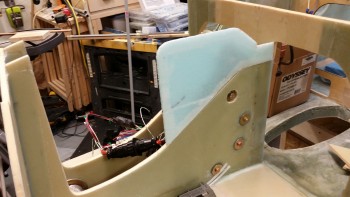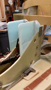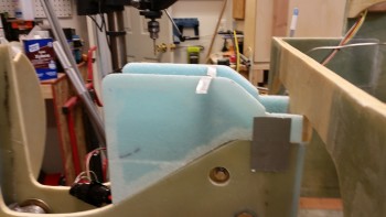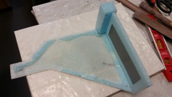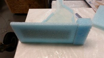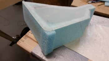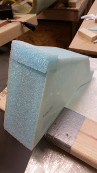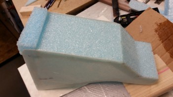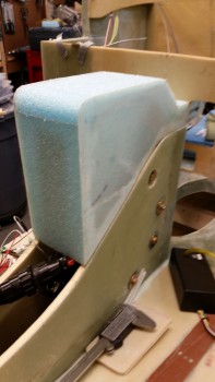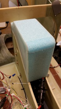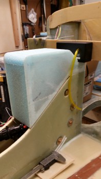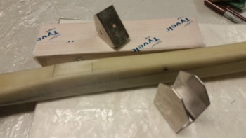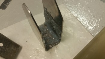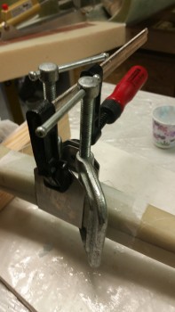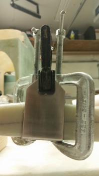
Chapter 13 – Cover end in sight!

I started off today looking everywhere for about an hour in the DC area for a friggin’ 1″ long 2-56 or 1-72 set of screws for the left side microswitch pair on the nose gear actuator.

No joy.  I called Fastenal, Grainger, etc. and no one had it.  Amazing.

I decided to press forward with the build and scrounge for the screws later on.  To be clear, I have 2-56 x 3/4″ screws on order with ACS that I’m fairly certain will work, but I wanted to try to get the gear up/down warning microswitch mounted today to get it checked off the list, especially since my ACS order won’t arrive for another day or so.

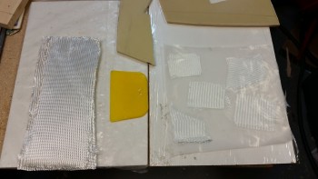
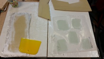
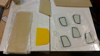
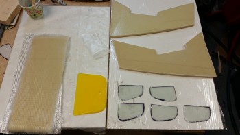
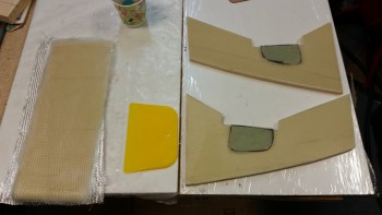
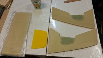
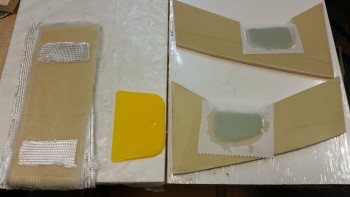
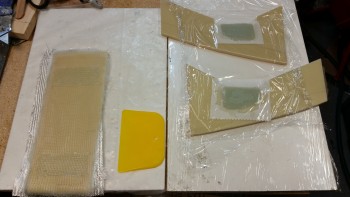
My first order of the day was to reinforce the areas on the aft corners and the front lip to better hold mounting screws.  I laid up a 2-ply BID pad on both back side corners and another at the lower front lip.

Apparently the epoxy estimator lobe in my brain is malfunctioning and once again I had way too much epoxy left over for the 3 small layups I did, even after peel plying them.

I was wondering what I should layup when the conversation that I had with my buddy Greg last night popped into my head.  I was explaining why I was working on the NG30 cover now vs later, primarily because I had much easier access to work on it since there are no sidewalls in my way.  Then it hit me suddenly: time to glass the forward NG30 cover!

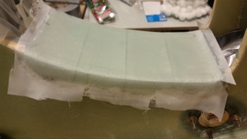
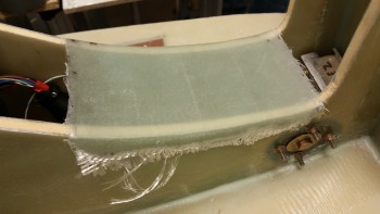
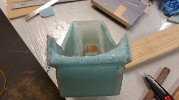
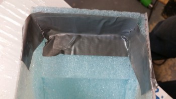
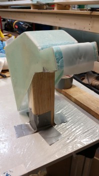
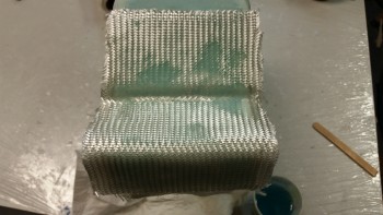
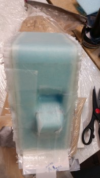
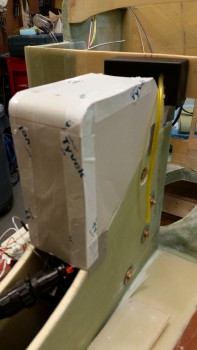
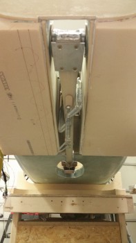
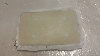
I quickly put plastic in front of both the gear actuator and the NG6B gear strut pivot & taped them up to protect them from any errant epoxy.  I then grabbed duct tape and laid strips sideways over the hole, attempting to rid the surface contour of any fixable blemishes.  I then taped over the duct tape with foil tape and proceeded to lay up 4 plies of BID.  I then peel plied the layup.
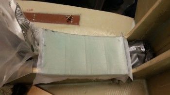
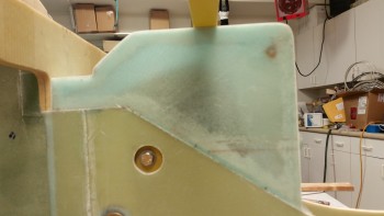
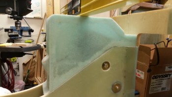
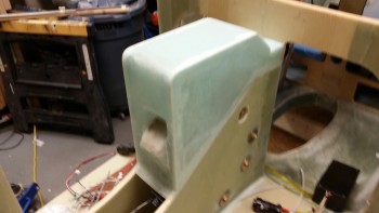
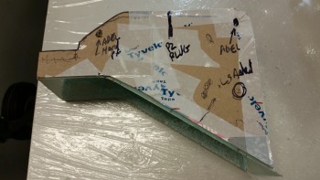
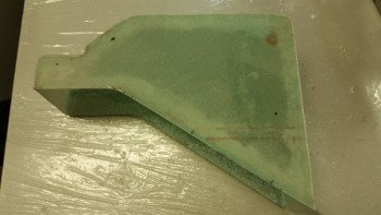
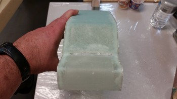
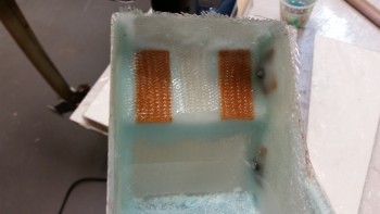
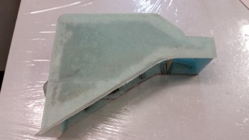
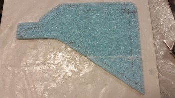
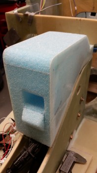
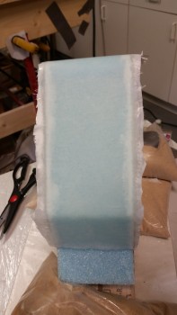
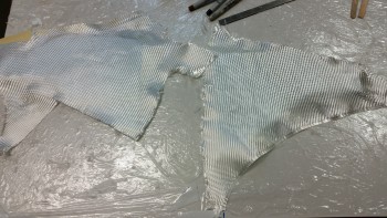
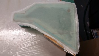
Forward NG30 cover

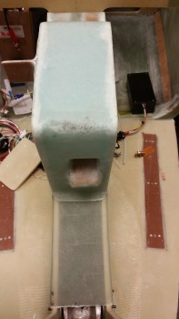
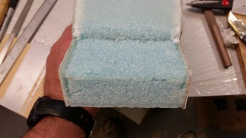
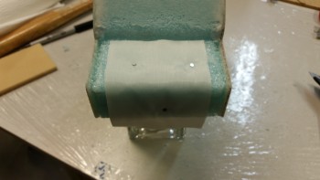
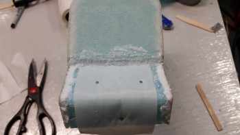
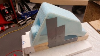
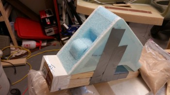
I have to say that although there were some ridges on my “mold” due to the tape, after the 4th ply it was pretty darn smooth.  I then took a number of pics of the new forward NG30 cover.
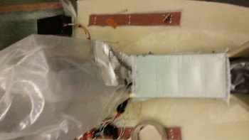
Forward NG30 cover

Forward NG30 cover

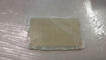
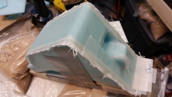
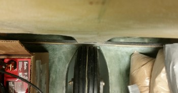
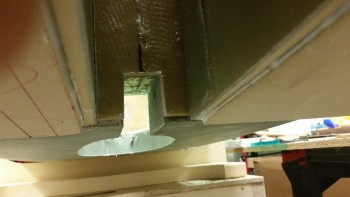
Here’s what’s left of the foil after I popped off the cover.
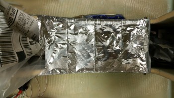
Forward NG30 cover

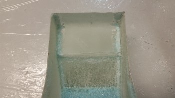
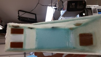
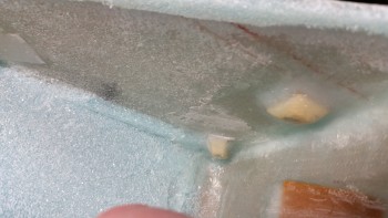
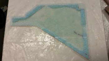
And here’s the underside of the cover.
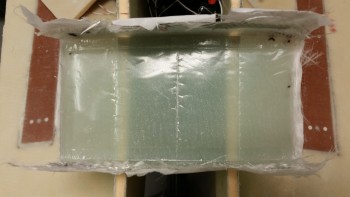
Forward NG30 cover

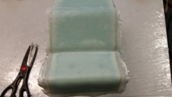
I then removed the peel ply.

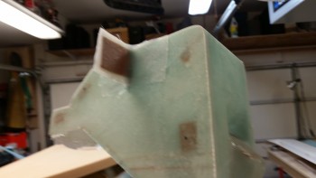
Forward NG30 cover trimmed

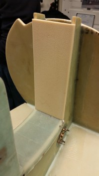
I rough cut the edges with scissors and took a few more pics of it mocked up with the aft NG30 cover.
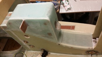
NG30 covers mocked up

NG30 covers mocked up

Fwd NG30 cover mocked up with F4.1

I then started working on the NG30 cover mounting to the NG30 gear box assembly.  The NG30 cover will mount with 6 x #8 sized screws (front, middle, back).

The back & front screw point configurations have the screws going through the NG30 cover skin into nutplate assemblies mounted on the NG30.  However, the middle set of mounting screws will start with a small hole in each side of the NG30s, with the screw going through the NG30 side into a nutplate that is mounted on a short tab that is in turn attached to the inside of the NG30 cover.

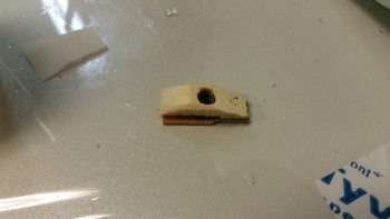
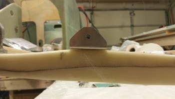
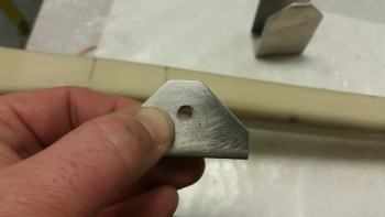
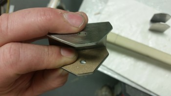
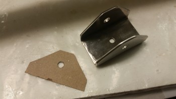
Here are the two mounting tabs that will get K1000-8 nutplates installed and will be mounted on the interior side panels of the NG30 cover.  I glassed them with 3 plies of BiD on one side & 2 plies of BID on the side that will get glassed into the NG30 cover, since that will add rigidity to that side for all but the bottom 1-1/2″ of the tab where the nutplate is.  The 5 total plies made for a very rigid, but still flexible mounting tab.
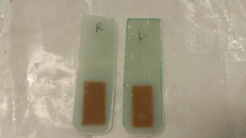
Aft NG30 cover mounting tabs

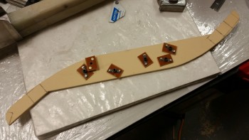
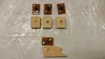
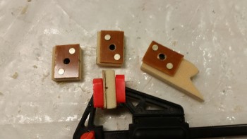
Here’s a shot after I installed theK1000-8 nutplates.  Also, in addition to these I made up 6 K1000-8 nutplate assemblies with phenolic bases (not shown).
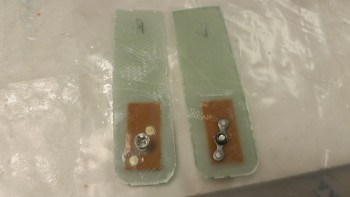
Aft NG30 cover mounting tabs

I then drilled a hole into the side of each NG30.
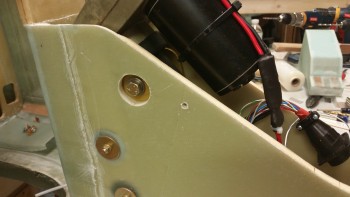
Holes drilled for mounting tabs

And then installed the mounting tabs.  I’m working the installation of the mounting tabs a little backwards as you can tell.  The tabs go into the assembly first, and then will get mounted to the actual cover later.
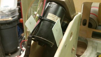
Aft NG30 cover mounting tabs installed

To find out how wide I’ll need to adjust (add to) the width of the cover side panel before permanently attaching the tab, I merely slid it over until the mounting tab stopped it.
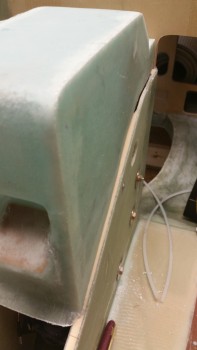
Checking spacing

I then measured the gap and got a pretty close estimate of how much material will need to be in between the mounting tab and the interior of the side wall.
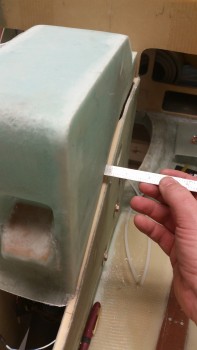
Checking spacing

To know for certain where the tab was I placed a bright light behind the cover and simply traced the mounting tab onto the side of the cover.  I did this for both sides of course.
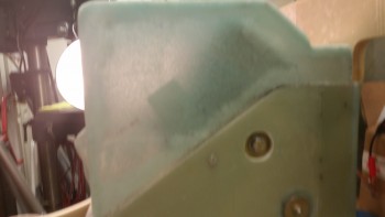
Mounting tab silhouetted

I then grabbed the AEX module and the SkyRadar ADS-B receiver and mocked them up on the NG30 cover.
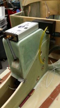
AEX & ADS-B receiver mocked up

Below is a shot of what I was really after here: I needed to know where to put the hard points on the inside top of the NG30 cover for the mounting of the Sky Radar ADS-B.
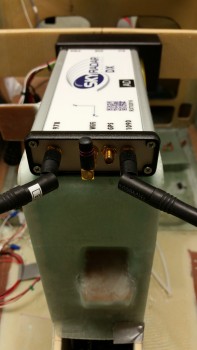
ADS-B receiver mocked up in place

Lastly, here’s the final structural layup on the NG30 aft cover.  I prepregged two 1-ply pieces of BID for corner tapes, then 6 phenolic inserts that will serve to hold the ADS-B receiver in place, and finally, one large piece of BID.

The plan was to use flocro to secure the phenolic inserts into place, then glass a 1-ply BID corner tape over the inserts and the corners along the top and each side.

I spent a good half hour prepping the interior of the NG30 cover for glass by sanding it.
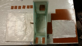
Last structural layup on aft NG30 cover

This shot shows all the phenolic inserts in place with flocro.  Again, I used florcro to get the weight savings of micro combined with the strength of flox.
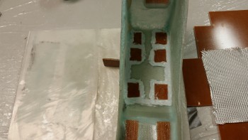
Laying in phenolic hard points for ADS-B

Here’s a shot with the layup completed.  Again, this is the last structural layup for the construction of the aft NG30 cover.  In fact, the only layups I have left will be for the center mounting tab pieces onto the interior surface of each side panel.  I would have laid the mounting tabs up tonight, but it was late and that layup required me to surface prep the side panel glass with the Dremel tool.  And since I was already chided earlier this week from a neighbor very nicely inquiring if I was the cause of the loud power tool noises emanating from this end of street, I figured I’d better be good . . . for another week or so!
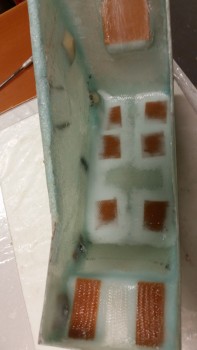
Final structural layup on NG30 cover!

Tomorrow I should be able to finish the aft NG30 cover.  I’ll need to get it mounted to the NG30s, and then I’ll clean up all the nutplates, drill the mounting holes for the connectors, etc.
Chapter 13 – Gimme some cover!

A NG30 cover that is!

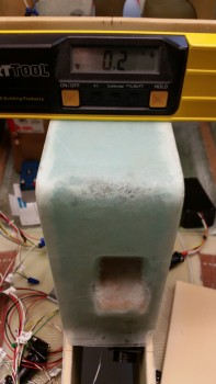
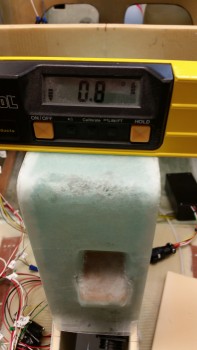
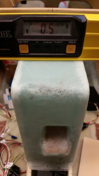
Today I started out by checking the angle of the longitudinal axis with my digital level across the longerons.  I got a reading that said the right side (looking from nose to aft) needed to come up 0.2°.  This also gave me my baseline for checking the NG30 cover.

When I checked the NG30 aft cover it showed that it needed to come up 0.8° on the right side (again, looking nose to aft).  When I pressed down on the back left corner (as oriented in the pic below) I was able to take the number down a notch to 0.7°.

Now, I wasn’t trying to be a perfectionist here, but I did want to get it as close as possible, primarily because I’m fairly certain I’ll be mounting the Radenna SkyRadar-DX ADS-B IN receiver on top of the NG30 aft cover.  I want the top surface of the NG30 cover to match the longerons in longitudinal axis since the SkyRadar has a built in AHRS and needs to match the axes of this aircraft to provide attitudinal information.  Getting the cover as close as possible to the longerons will just make things easier when installing the ADS-B receiver, and help ensure better info if ever a backup attitude reference is required.

Checking Longitudinal Axis

I slowly sanded down the edges on all sides at various points to get this cover dialed in.  I did focus on the left side (again, relational to the pic below).

Checking Longitudinal Axis

And after about a half hour, success!   Add this time to the original half hour rough cut on the bottom edges after the sides were glassed and I spent about an hour total by this point on getting the cover level.

Correct Longitudinal Axis!

Here are a few shots of the level NG30 aft cover.  There are still some minor gaps that will be taken care of during the finishing process.

Right Side shot

Left side shot

NG30 cover

Now, I made an oops as I was ripping off the peel ply from the right side layup from last night.  It was pretty tough at one point so I put some muscle into it, and apparently some of my fingers where on the back foam plate because it gave way and the foam snapped.

Oops!

Not really an issue since  I planned on removing this foam anyway.  Luckily, the foam broke into 2 big pieces, so I merely taped them back into place with duct tape.

Duct tape will fix it!

Here’s my repair.  See?! Duct tape will fix anything!

See?! Fixed!

Since I am removing most of the aft foam almost immediately after the glass cures, and then laying up the aft inside area of the cover, I went ahead and embedded some peel ply to ensure the main surface was prepped nicely for glass.

Embedded peel ply

I then taped up a quick glassing tower for the layup (it was a bit wobbly if I really applied pressure since it was only taped to the protective plastic on my board, but this helped me keep my touch lighter on my improvised foam repair).

Temp glassing stand

I cut out wedged-shaped trenches along the outer side edges and filled them with flocro.

Flocro in corner trenches

I then laid up 3 pieces of BID in 2 plies.  The first ply is from the corner seam aft, the second is from the corner seam forward, making up the first ply of the layup.  The third piece of BID and second ply covers the entire area of the first two pieces of BID.  I wasn’t sure how well the BID would lay down in the tight 90° corner, so I split the first ply into 2 pieces.

Last ply layup

Here’s the final result of the aft end layup.  I have to say I really wasn’t looking forward to this layup, but it turned out to be one of the better, more relaxing layups that I’ve done on this cover.

Peel plied & done!

I also laid up 1 ply of BID on the backside of the second draft plate that I cut and glassed last night.

Second side of second draft plate

To mark where my nutplate assemblies will go on the right side of the cover, I grabbed my original template and punched holes with an awl everywhere it indicated a nutplate assembly mount.

Notes on template

I then simply marked the right side surface with a Sharpie through the holes I had just made in the template with the awl.

Marked nutplate mounting spots

Since 2 of the new nutplate assemblies going inside the cover will be very close and adjacent to the aft layup area, I went ahead and prepped that area first before floxing & glassing in the nutplates.

I dug a bunch of foam out and then pulled the peel ply from the inside of the aft area.

Embedded peel ply removed

Here’s a better shot of the foam & embedded peel ply removed.

Embedded peel ply removed

I then finalized the prep of the aft area internal glass for a 1-ply BID layup.

Aft internal cover prepped for layups

Since I was still helping my buddy Greg with his Christmas tie, I didn’t get a chance to take a pic of this layup until an hour or so later,  If you look closely you’ll see that I installed 3 new nutplate assemblies on the right side panel, and embedded 2 pieces of phenolic on the aft pad where the AEX will get installed.

Nutplate assemblies glassed in place

I then took a piece of phenolic that I had precut and mounted it the right side sandwiched between 2 x 2-ply BID prepregged BID tapes.  This mounting tab will house the permanent P2 connector coming from the main P1 connector at the front of the cover.  Then the AEX side P2 connector will plug into the mounted P2 connector.

Side mount for AEX P2 connector

I floxed and glassed two strips of 1/16″ phenolic in the back to serve as mounting hard points for the AEX box.

Embedded phenolic for AEX mounting

Here’s a shot of the nutplate assembly I glassed in last night (far corner) and the one I floxed & glassed in today (nearer camera)

Forward nutplates

I know I said I was going to be done with the NG30 cover today, but that was before my buddy Greg needed my help.  I think I should have almost all, if not all, of it completed tomorrow.


Chapter 13 – Slow n’ Steady

I started out today trying to lock down a bunch of hardware for the plane build.  It took a while to research some of the items –about 3 hours total– but I found a number of the items I was looking for and started compiling various orders for Aircraft Spruce, Mouser, etc.

I then went to the shop and pulled the peel ply from last night’s layup on inside of the front cover face.  I cleaned up peel ply boogers and a few rough glass edges.

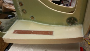
Glassed phenolic insert

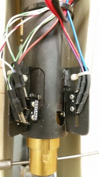
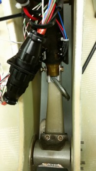
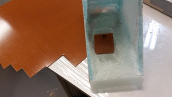
I then set about to add the second microswitch (for the gear up/down alarm) to the gear actuator housing.  I pulled one of the screws from the current microswitch and when I went to put in a longer screw it was then that I realized that the set of screws I just ordered where the wrong size!

Missing a MicroSwitch!

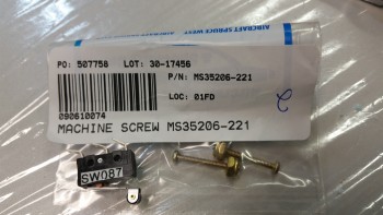
Here are the incorrect screws shown with the CORRECT microswitch.  Well, it looks like there’s a bit more research in my future!

THE WRONG SCREWS!

Then, as if things weren’t pissy enough, I found that Napster stole the Christmas tie that I was making for my buddy Greg!  Ha!

Stolen Tie

So with the adding of the microswitch to the gear actuator assembly a total bust, I pressed forward with glassing the sides of the NG30 cover.  With the initial sides glassed with only one ply of BID, the sides are sunken inwards a bit.  So before I glassed the sides I wanted them set out about 0.050″ each side so that they would likely set a little straighter.  I cut 4 popsicle sticks to 3.67″ to make the outboard side-to-side measurement just over 3.7″.  Even if they cured a little bowed out that would be much better than sunken inwards.

Spacers installed

Since there’s a bit of a gap at the cover’s bottom edge dogleg and the NG30’s dogleg on the left side, I wanted the glass to overhang the edge so I could cut it to the correct length after it cured,

Left side prep for glass

Here’s the left side glassed with 2 plies of BID, and after the peel ply was pulled & it was razor trimmed.

Left side after 2-ply BID layup

To extend the glass lower on the right hand side I cut a foam extension & glued it in place with 5-min epoxy.

Right side prep for glass

Here’s a shot of the right-side foam extension glued into place.  After it cured I sanded it to  ensure it was level with the existing outboard side glass surface.

Foam extension 5-min in place

I then laid up 2-plies of BID and peel plied it.

Right side after 2-ply BID layup

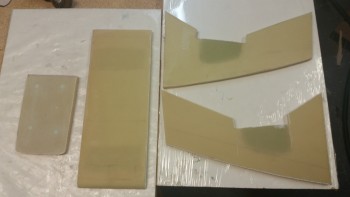
I overestimated the amount of epoxy required for my right side layup, so I had a fair amount  left over.  I grabbed a piece of 1/4″ thick PVC foam and glassed it with 2 plies of BID and then peel plied it.  This piece will serve as the lower of two draft plates to keep the cold air out.

Lower draft plate: "Tuning Fork"

Tomorrow I’ll work to finish up the NG30 aft cover: glass top inner BID tapes, nutplates, mounting tabs, etc.


Chapter 13 – It’s a Tie!

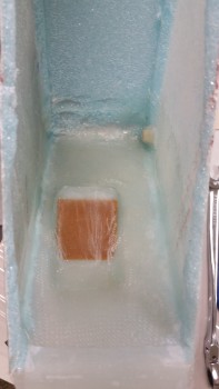
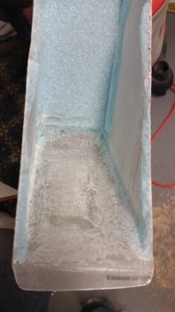
I had a fair amount of running around today so I didn’t get much done.  I started by clearing out the foam from the inside front face of the NG30 aft cover.  My main concern was clearing the foam off the inside of the surface where the phenolic plate insert will go for reinforcing the glass when the gear actuator P1 connector is installed.

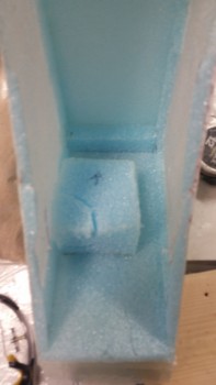
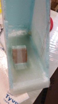
I sunk my razor knife into the foam when it hit me that I had not yet taken a pic of the inside of the cover with the added foam plug that allowed me to make the female side depression in the face of the cover for the P1 connector.  So I took a pic.

Foam plug for P1 connector

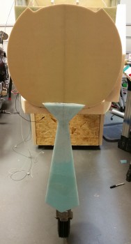
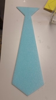
Just as I started in on my plane-building tasks my buddy Greg stopped by for a visit, and to also ask for my help in assisting him in making a Christmas tie in an attempt to win the “Best Christmas Tie” award at his work’s annual holiday party.  Last year we made it out of wood, so this year I though it would be cool to make it out of spare blue foam and glass it.  This burned up a few hours, along with just visiting & BS’ing in general.

Buddy's Christmas Party Tie

Back to airplane stuff, I was able to clean out the foam & clean up the inside of the front face of the NG30 cover.

Inside cover face cleaned for layup

I then cut out the 1/16″ thick phenolic insert to embed in the layup to add strength to P1 connector mount.

Checking phenolic insert fit

I lightly sanded the phenolic plate on each side.  Once I got the phenolic insert ready to go, I then took a few minutes to prep a nutplate by embedding it into some H250 foam.

K1000-3 Nutplate Assembly

I laid up a small piece of BID just big enough to cover the phenolic insert after floxing the insert into place.  I then covered that small ply of BID and the rest of the inside front face with another large 1-ply of BID.  I overlapped the final ply of BID onto the side walls by a good 1-1/2″.

I then floxed the nutplate into the foam, and the entire nutplate assembly io the upper right side corner of the NG30 cover (lower right as the pic is situated here).  The large 1-ply BID just missed where I floxed in the nutplate, so I used a small patch of BID to cover the nutplate assembly and overlapped it about a half inch on the big BID piece that I had just laid up inside the NG30 cover.

I then peel plied the face of the glass covering the phenolic insert, and the very front of the BID play at the bottom lip of the front face (pardon the blurry pic).

Inside cover face BID layup

I then cut 4 pieces of BID on the cutting table to layup on the cover sides tomorrow after I clean up this layup.

Tomorrow I’ll also install another 2-3 nutplate assemblies on the inside of the cover, all on the right side –at least for now– all for wire-containing Adel clamps.  I also have to work the glass on the cover sides to enable mounting the cover to the NG30s.


Chapter 13 – A Cover Up Job!

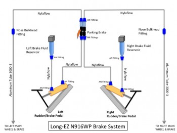
Today I started off by doing some research as I watched some football.  The first thing I had on my list to figure out was the exact configuration of my brake line components.  I did some poking around on the Matco website to figure out what components go where for my brake system.  I found the information I was looking for and was able to tailor it to the brake system components I have on hand.

Again, being a true Neanderthal and PowerPoint Ranger, I jimmied up a quick PowerPoint slide to display what was going on with the brake system.  One reason I was checking out my brake system is because I wanted to confirm what goes where in the nose so I can plan better as I build the NG30 aft cover, and will soon glass in the nose side walls.

Brake Line Configuration

I also spent about an hour doing some digging around online for information on my electrical system.  Really, I was focusing on a lot of the little bits n’ pieces that will be required to finalize the mounting of various stuff in the nose area, such as Adel clamps, and hardware to mount those Adel clamps: screws, nuts, bolts, washers, etc.
I also ordered two different sizes of heat shrink tubing for my shrink wrap label maker.  Now I have at least the first round of wire labeling for my wires ranging from 4AWG to 22 AWG.

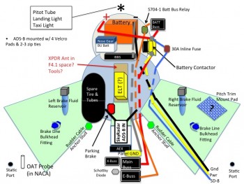
I also updated my nose component diagram again and included it here.

Internal Nose Components

I then headed out to the shop to razor cut the edges of the NG30 cover side panels.  Here’s the left one after I mocked it up on the NG30.

Left NG30 cover side panel

And here’s both trimmed side panels mocked up.

NG30 aft cover side panels

A side view of the NG30 cover side panels.

NG30 aft cover side panels

I then spent a few minutes figuring out what foam was going to get cut away & which foam would stay.  Here’s the marked up left NG30 cover side showing the foam cut lines.

Marking side panel for foam removal

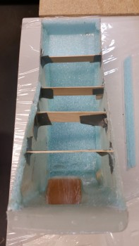
Here’s the final foam trim for the left NG30 aft cover side panel.  Out of curiosity I weighed this side panel and it came in well under 1 oz.

Left side panel foamed removed

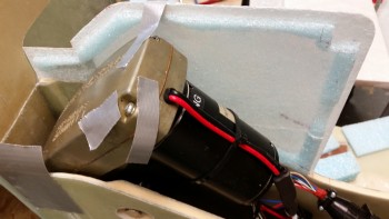
I then double-checked the actuator motor housing clearance with it back on top of the left NG30.

Checking clearance with side panel

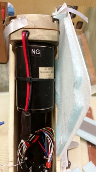
Here’s a front view of the same.

NG30 cover side clearance

I then cut out the 1/4″ front foam panel and the front top corner foam piece.  Below is a shot of the pieces mocked up to ensure that they fit.

Mocking up front foam pieces

I then attached these foam pieces to the left side panel using 5-min glue.

Front foam pieces 5-min glued in place

Piece by piece, I cut and then glued the top and aft blue foam panels into place on the left NG30 side panel.  I really focused on ensuring that these glued-in panels were truly perpendicular to the side panel.  Note that I intentionally cut the top front corner piece oversized to allow for sanding it down to a curve that’s “pleasing in shape” …. ha!

Center foam pieces 5-min glue in

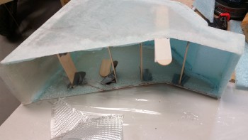
Here’s a shot of the NG30 aft cover after I glued in all the center foam panels & pieces.

NG30 aft cover as one unit

And an aft side view.

NG30 aft cover as one unit

After sanding the foam & glass edges to shape, I mocked up the cover on the NG30 nose gear box.

NG30 cover mocked up in place

NG30 cover mocked up in place

I grabbed the AEX box and put it in its spot to check how it fits.  Spacing looks good!

NG30 cover mocked up with AEX

As I took a break for dinner, I was thinking about the front of the NG30 aft cover and had a mini epiphany.  I wasn’t sold on the straight horizontal positioning of the nose gear’s P1 connector.  I doubled-checked it when I got down to the shop and sure enough, the P1 connector would fair much better if it was positioned at an angle vs attached straight through the front panel.  Although I knew it would be a bit more work, I wanted to optimize the nose gear actuator’s P1 Amp/CPC connector’s fit into the NG30 cover.

I drew out the plan on a piece of cardboard, then transferred that to another piece of cardboard to make a template out of it — which looked like nothing more than an “S” if you  wrote it without any curves (a 3-lined zig-zag).  I transposed the template markings to the side of the cover.

I needed to make what essentially would end up being a male mold (lower) and a female mold (upper) in the front face of the cover for the BID to end up curing in the correct shape.  I made the front angled panel piece (lower/male) to match the profile of the template and markings on the side of the NG30 cover.  With that piece completed, it was then time to figure out how make the angled pocket (upper/female) to finish off the angled mount for the P1 connector.  I ended up adding an oversized chunk of foam on the back side of the front foam panel piece on the inside of the cover.  I 5-min glued it in place at the same time I glued the front “ramp” (male) piece in place, and stood there holding the two in place for about 5 minutes (what a coincidence!) until the epoxy set up.

Nose gear P1 connector angle mount

Now, I have been contemplating how exactly to go about glassing the NG30 aft cover.  I wanted to get a good glass overlap, perhaps even an entire piece of BID over all of it, but the cured 5-min glue and the edges were being amazingly stubborn as I toyed with radiusing the corners.  I will say that I really do like the look of the sharp square corners, but I don’t like the idea of digging around in the confined nose space and smacking my arm on that sharp corner.  Oh, well, who cares how it functions as long as it looks awesome!  haha!

I mounted the NG30 aft cover assembly onto a 2×4 to ensure that this incredibly light assembly didn’t get away from me as I was glassing it.

I then cut a small trench along the corner edges and cleaned them up in prep for Flocro.

NG30 aft cover secured for glassing

I mixed up some epoxy with fast hardener and then whipped up some Flocro with about 60% Micro & 40% Flox.  I used Flocro to keep it light but still have good strength in the corners.  I applied the Flocro along the edges of the foam in the mini wedge-shaped trenches that I had just created to make my “Flocro Corners.”

NG30 aft cover secured for glassing

I then laid up 2-plies of BID on all but the very aft area of the center piece of the NG30 cover.  I had meant to take the layup farther aft, but the connector mount area took up a bit more glass than I thought.

I peel plied the entire layup since I’ll probably add one more ply of BID to this center section area.  I may even still radius the corners a bit and layup BID overlapping from the sides over onto the top & front center faces.

NG30 aft cover center strip glassed

Here’s a shot of the aft side of the layup.

Aft side of glassed NG30 cover

And another shot of the majority of the layup (there’s about a 1.5″ strip overlapping onto the angled panel that dives down into the notch for the AEX… shown in above pic).

NG30 aft cover center strip glassed

Tomorrow I’ll work to finish up the myriad of little tasks that need to be completed to finish up this NG30 cover.  I estimate that I’ll finish this cover either Tuesday or Wednesday.


Chapter 13 – Big Milestone . . .

Today was one of those big milestone moments for me in the build of this Long-EZ.  Just like taking that first pic sitting inside your freshly glassed fuselage, this was one of those days that I had been wanting to get to for a long, long time.  I finally got the nose gear official installed, both mechanically & electronically, and so far it’s all working pretty darn good.  I’ll discuss the gear a bit later, but for now, let me start detailing my day’s work chronologically,

I started by taking 6 of K1000-3 nutplate assemblies that I made up last night down to the shop along with a scrap piece of the über dense H250 foam.

Electrical frame nutplate assemblies

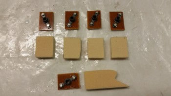
I cut rectangular pieces out of the foam to serve as a base for the individual nutplate assemblies.  The odd foam piece below the row of 4 standard looking rectangles will go on the aft side CL of F28, and hang aft at a very sharp downward angle.  Again, this is for mounting what is essentially a giant “T”-shaped electrical components & avionics “tree.”

Electrical frame nutplate assemblies

I then worked the foam pieces to allow me to embed a K1000-3 nutplate into the foam.

Electrical frame nutplate assemblies

Here are the end results.  Now, I had every intention of mounting these onto the backside of the F22 center strut (just forward of the nose wheel cover) and on the bottom aft side of F28, when I took a break for lunch.  Reviewing in my mind that I still needed to construct the electrical component structure (I nicknamed it the “Triparagon” … don’t ask me why, but if the Avengers/SHIELD can have a building with a cool name like “Triskelion” than my electrical tree/tower/structure can have a cool friggin’ name too!  Ha!), I thought why should I install these now when I can simply bolt them to the structure later, put the whole thing in place with some 5-min glue on these puppies and have all my bolt holes aligned perfectly.  Duh!  So, I bagged these suckers up and put them on hold.

Electrical frame nutplate assemblies

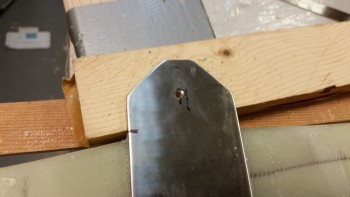
Having successfully avoided yet more work, I then moved on to drilling the outer NG3 bracket on the now cured gear strut. I messed around for maybe 10 minutes dialing in the hole location, and even though I used a hole punch my bit slid over to the left by about a 1/16th of an inch. Stainless steel being what it is, the hole seemed to magically move even further left when I used a bigger bit!

The hole I started on side #1 was definitely off center to the hole on the interior NG4 bracket.  So, I left the first hole alone and since I had access to side #2 from the INSIDE, I simple drilled the other side through the first hole.  I made sure that the second hole was drilled spot dead center.

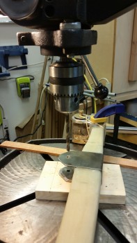
I then concentrated on drilling out the second hole to about 3/16″ in diameter.  Before I took this whole shabang over to the drill press, I grabbed a smaller bit (about ~1/8″) and drilled from side #2 back into the first drilled hole in side #1, this time from the inside.  However, my entire goal here was to simple remove a good amount of steel so that when I drilled through side #2 on the drill press and then got to the messed up hole on side #1, there wouldn’t be much resistance to the 1/4″ bit to do its job.  When I finished with this step I had a nice 3/16″ hole in side #2, and a very odd looking figure “8” or ∞ looking hole in side #1.

Drilling NG3 stainless steel bracket

Once on the drill press, I started with a 7/32″ bit to basically ensure that the hole was centered and remove just a bit more material.  I ran it down to the lower side and barely kissed the metal in the hole just to remove a bit more material.  I wanted the sides of both the upper & lower holes to guide the 1/4″ bit, so I really didn’t try to do much on the lower (∞) hole with the 7/32″ bit.

After I loaded up the 1/4″ bit, it nearly slid through the first hole and made a beautiful clean (read: not jacked up!) hole on the bottom hole (the original side #1).   With straight, clean holes that ran entirely through my NG3 & NG4 brackets, I was a happy man!

[One point of note: as I was installing the NG3/NG4 brackets over the 1-ply of BID last night, the brackets slid down the gear strut another 0.17″ making the total distance from the NG6B pivot to the center of the NG3 bolt to be 6.47″ total (and final).  I wasn’t concerned in the least since I could always adjust the gear strut travel with the microswitches, and lower is actually better for leverage, and possibly strength(?).

Final 1/4" drill pass on NG3/NG4 hole

After reinstalling the nose gear assembly, I made the requisite nose gear test video to make it official!

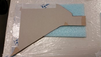
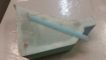
I then started designing my 2-part NG30 cover.  Here’s the aft part that I came up with using scrap cardboard as the build material to construct the mockup.

I’d like to point out that the biggest reason for me covering the NG30 nose gear box is to keep cold air from rushing into the cockpit.  However, another huge reason is that it gives me a platform to hang & mount a bunch of stuff all over to help organize the front nose area.  I think that by designing the right NG30 cover I will really optimize the space I have available for mounting all my forward mounted components.  In fact, in the pic below you can see the AEX module mounted into the aft area of the NG30 cover.

NG30 aft cover

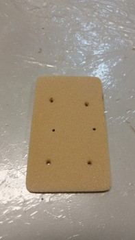
I pondered for a good while on how I was going to construct the aft NG30 cover.  The front NG30 cover will be fairly easy since it’s essentially a 4″ x 6″ flat plate with screw holes.

Since I had very close to what amounted to be a basic box, I didn’t want to pull the crappy, messy urethane foam out to start carving away.  I had simple lines here and the more I thought about it, the more I came to the conclusion that I needed to construct this cover in steps, first of all, and use some foam in the process.  I would love to have a 3-ply BID cover with no foam, but I’m not going to A) remove the nose gear actuator to fill the area with foam to carve, or B) fill foam in around the nose gear actuator to carve, since there’s really not that much room around it to begin with.

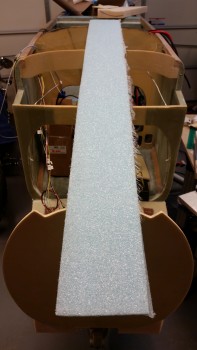
As I was digging around for possible solutions, I ran across this foam piece in the closet.  I’m pretty sure that this scrap piece was a spar cap cutout.  It was maybe a 1/4″ thick and I thought this would surely do the trick.

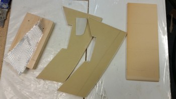
Scrap blue foam for NG30 cover sides

I cut the blue foam piece to width to match the total width of the NG30 cover side panel.  As you can tell from the pic below, I was going to have to micro two pieces together to get one side panel.

Cutting scrap blue foam for NG30 cover

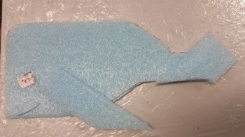
And then guess who stopped by?  That’s right!  Why it’s Banarbas (aka “Zippy”) the Whale!  haha!  (Sorry, couldn’t resist!)

The NG30 Mascot: Barnabas the Whale!

I grabbed a couple pieces of scrap BID and ensured that one per side fit.

Scavenged BID

I then laid up 1-ply of BID on each side panel of the NG30 cover.  I only used one ply because a lot of phenolic plates, etc. will be embedded into these NG30 cover sidewalls, so at least 2 more plies of BID will be added to this 1-ply of BID.
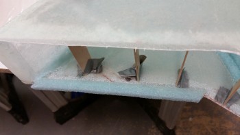
Also, you may note that I only micro’d the edges of the NG30 cover foam side panels.  The reason why is that I’ll keep a good majority of the edge foam throughout the cover construction since it will in fact be corner foam as the cover gets completed.  However, the majority of the foam in the middle ‘field’ areas will get removed.

Face off! 1-ply BID layup

Since I will be adding subsequent plies of BID, I went ahead and peel plied both NG30 side panel layups.

NG30 aft cover sides peel plied

Tomorrow I’ll attempt to complete the construction of the aft NG30 cover.  Once the NG30 cover is complete, I’ll start working on the glassing in the nose side walls.


Chapter 13 – Gear Strut Stuff

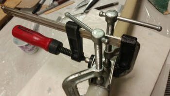
I started off today by testing the gear strut’s up & down travel limits.  To do this I clamped the NG4 bracket to the top of the gear strut with 2 “C” clamps.

Checking gear strut travelChecking gear strut travel

Although a little difficult to see in this pic, the clearance aft of the nose wheel to the instrument panel is about 0.2″.

Nose wheel clearance

I also marked & sanded down the sides of the F22 gear strut channel.  I sanded about .06″ off the right side (left in the pic) and about .02″ on the left side to widen the channel just a bit more since there was some rub marks on the gear strut.

Sanded & widened F22 channel

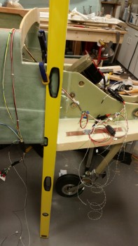
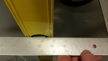
To figure out where the nose wheel should be in comparison to the fuselage, I clamped a 6′ level to fuselage aligned with F22 to essentially carry the F22 line down to the floor.  I clamped the level on the aft edge so that the level was perpendicular to the fuselage centerline (and not flat against the inward curving nose portion at F22…this made for a gap between the front inside edge of the level and the fuselage sidewall.  The back inside edge was flush with the fuselage side).

F22 alignment

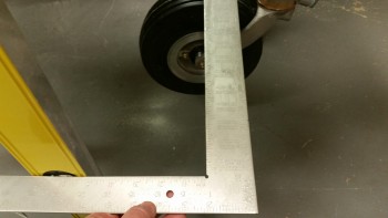
I then used a square to check the relationship between the nose wheel axle and F22.

According to the Long-EZ plans the axle should be at Fuselage Station: FS 17, so 5″ forward of F22.  It took me 3 adjustments of the down travel microswitch to get the axle moved forward to FS 17.

Checking axle FS from F22

A close up showing square markings and the nose wheel axle 5″ forward of F22, making the axle location at FS 17.  I was actually shooting for a measurement of 5.2″ to 5.5″ (FS 16.5 to FS 16.8) on the square to make allowance for the weight of the aircraft compressing some of the natural gear spring action when on all its gears.

Checking axle FS from F22

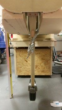
Here’s a shot of nose gear & wheel down at the correct level.

Setting gear actuator microswitches

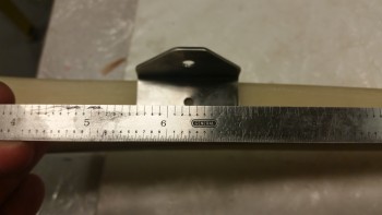
I then removed the gear strut to attach the NG3 & NG4 brackets.  Although plans calls for mounting the NG3 bracket at 6.71″ ± 0.05″ from the NG6B pivot point, after setting the microswitches for the up/down limits the measurement between NG6B and NG3 came out to almost exactly 6.3″.

NG3/NG4 mounted at 6.3"

I would have actually moved the NG3/4 bracket a little higher on the gear strut, but I wanted to keep NG4 inner bracket on the thicker, straighter part of the gear strut and minimize any weird, undue stress to the gear strut that might result from mounting it higher and at a narrower area.

NG4 at 6.3"

The pic below shows the sanding that I did on the NG4 bracket before floxing it into place. Also, although hard to see, is the cardboard template I made of the inboard side of the NG4 bracket.  I’m hoping that I can use this to help drill the hole in the outer NG3 bracket, which comes un-drilled.

Making NG4 inboard template

Here’s some better shots of the cardboard template.

Making NG4 inboard template

Inboard NG4 template

Now, the original plans state that 2-3 plies of BID should be wrapped around the gear strut before floxing the NG3 & NG4 brackets into place.  However, the reason for this is simply because the original gear strut –as pointed out in the plans– was too narrow and the BID needed to be added to fill the gap.

Conversely, according to the installation instructions that came with the nose gear actuator, Jack mentions nothing about adding BID and simply says to flox the NG3 & NG4 brackets into place.  The NG3 definitely fit tightly enough that it could have easily been mounted with flox alone, but I like the idea of a ply of BID above and below the brackets to form a sort of hour glass configuration, if you will, to help lock the bracket into position.  It may just be in my head, but for a bit more peace of mind I decided to layup 1 ply of BID under the NG3 & NG4 brackets.

To add the 1 ply of BID, I had to sand the gear strut in the area that the NG3 bracket would be mounted.  I also prepped the rest of the area to ensure it was ready for mounting the brackets.

Prepping gear strut for NG3/NG4

After laying up my requisite 1-ply of BID, I then mixed up some flox with fast hardener.  I applied the flox to the inboard areas of the NG3 bracket.

Floxing up NG3 for mounting

I mounted the NG3 outer bracket and the NG4 inner bracket with 2 “C” clamps.  I also added another clamp (as per plans) to bring the sides of the NG3 bracket in at the top side of the bracket.

NG3 & NG4 brackets mountedNG3 & NG4 brackets mounted

Here’s another shot of the NG3/NG4 bracket mounting to the nose gear strut.

NG3 & NG4 brackets mounted

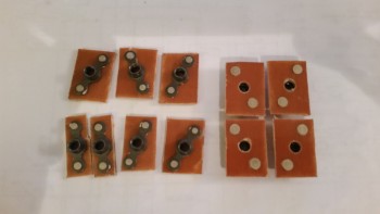
As the NG3 & NG4 brackets cured I sat down in front of the TV and cut up a bunch of 1/16″ phenolic pieces to make up some K1000-3 nutplate assemblies.  Eight of the 11 nutplate assemblies measure 1″ x 0.7″.  I’ll be using these for the electrical mounting plate that will be mounted just aft of the F22 center strut.  A couple of these will be used for the rudder cable hard points as well.  Finally, I’ll also be using a few of these to mount the NG30 cover.

K1000-3 nutplate assemblies

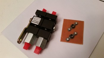
I also made up a double K1000-3 nutplate assembly for the Matco parking brake.

Parking brake nut late assembly

Parking brake nut late assembly

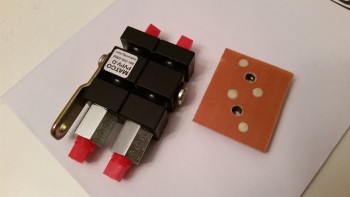
Here’s a side shot of the parking brake nutplate assembly with AN3-11A bolts installed.

Parking brake nut late assembly

Tomorrow I’ll be glassing in nutplate assemblies for the electrical mounting plate aft of the F22 center strut.  I want to get these in before I glass in the nose sidewalls so that I have much easier access.  I also plan on working on the NG30 cover, again since I’ll have more access with the nose sidewalls not yet mounted.


Chapter 13 – The AEX Killer

Yep, that’s me!  Or maybe I should have titled this post, “The Anatomy of a Repair.”

I had committed two grave sins in the wiring of the AEX P2 connector, one on each side. On the switch side I found pin 1, inserted that wire and then started filling in the wires per color from pin 1, first across and then down.  The only problem was that my first direction was as it should be if I was looking on the FRONT of the connector face, versus the mirror image it should have been on the back plate of the connector.  Ooops.  Well, as I said yesterday, I caught that after my discussion with Jack and remedied it.

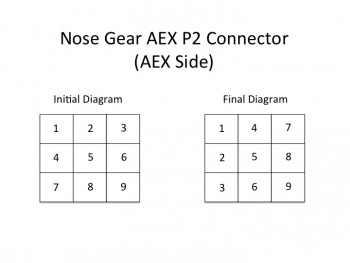
What I didn’t catch was the wiring mistake I made on the AEX side of the P2 plug.  When I had original diagrammed out the connector pins for that side, I realized that I hadn’t made the diagram in the normal top row=1-3, middle row=4-6, bottom row=7-9 pattern.  If you took the diagram and flipped it 180° from the upper right corner down to the lower left corner, that is what I ended with: column A= pins 1-3, column B= pins 4-6, column C=pins 7-9.  Thus, when I wired it up (mistake #3 actually, since it was LATE at night) I had the mental picture of the initial diagram (left below) in my head, not the correct one (right below).

AEX P2 Connector

I got ahold of Jack later in the afternoon to figure out the wiring issue with the electrical nose gear actuator.  With the AEX presumably Tango-Uniform, I thought that perhaps I needed another jumper on pin P2 along with pins 5 & 6.  I wasn’t sure about the jumper situation due the fact that since I ordered the AEX with my initial order of the gear actuator, I never received a jumper plug.

After some discussion Jack told me that if P2 pins 5 & 6 jumpered wasn’t getting the nose gear actuator to go back up, then I should try a jumper across pins 1 & 4.  Ok, I had the plan and was ready to execute.  I got off the phone ready to throw a jumper across pins 1 & 4.  Uh, the only problem was there was no pin 1.  The switch side of the P2 connector has 9 pins, and pins 1 & 2 are empty!

I called Jack back a few minutes later and gave him my report.  With that knowledge in hand, along with my trusty Fluke, Jack began to guide me through checking voltage readings from points A → B, X → R, etc.  I checked the relays by holding them up to my ear as I flipped the switch and was pleased to hear an audible springy click.  We checked the up-travel microswitch since this was the primary culprit: 12.86V on both sides.  All good.  Then I checked the main power wires going into the actuator motor.  12.86V on the red and .005V on the ground… all good.
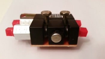
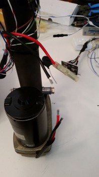
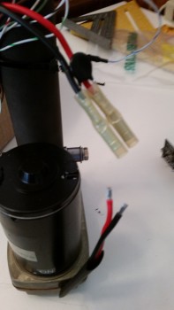
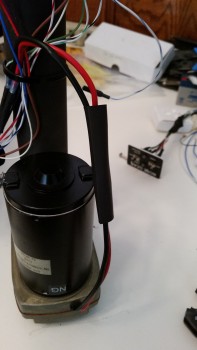
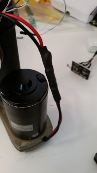
We were both stumped and Jack concluded that it appeared that the motor was bad. The problem was that these motors are amazingly robust and have an extremely low failure rate. Jack asked me to locate the heat-shrinked power connectors inches from where they exit the motor housing.  I did.  He then asked me to give all the wires a good tug to make sure they were connected nice & snug.  They weren’t.  The wires closest to the motor came out with the slightest pull.

That, my dear friends, seemed to be the real issue.

Fixing motor wiring

I asked Jack if I could run power straight to the motor with the inline fuse on the power side and he said yes.  When I did, I was pleased to have the motor jump to life.  Issue found!

(Thanks Jack, for such a great job talking me through the troubleshooting!)

[Note: Some of these pics are blurry since I’m using my phone camera … sorry.  I guess phone cameras are made these days primarily for taking selfies to post on FaceBook!]

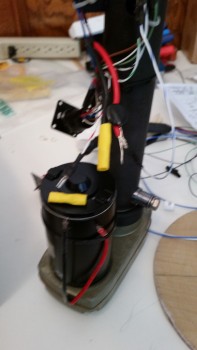
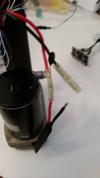
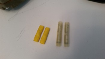
As you can see in the pic below, the yellow butt splice wire connectors are more automotive grade, which should have done the job ok, but for whatever reason here they didn’t.

Since the butt splice connector on the black wire was firmly in place, I started with replacing the one on the red wire.  I was able to pull it off with a firm pull.

Fixing motor wiring

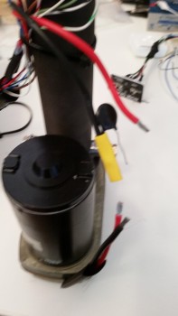
I then spliced on a higher grade butt splice connector that came in an electrical connector kit that I bought from B&C.  You can tell the difference between the two immediately in the pic below.

Fixing motor wiring

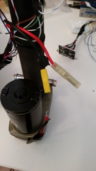
With the red wire butt splice in place, I then pulled the old connector off the black wire and crimped a new butt splice connector in its place.

Fixing motor wiring

Fixing motor wiring


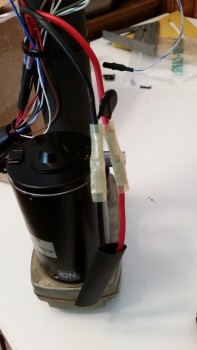
With the switch side completed, it was time to crimp the motor side wires into the butt splice connectors.  I had already found an appropriate sized piece of heat shrink and slid it into place before completing the butt splicing.

I crimped the red wire butt splice first, and then finished with the black wire.  It’s not easy to see in the pics, but the space that I had between the wires and the motor housing was fairly tight to get my crimper in place while still ensuring that the wires were fully seated into the butt splice connectors.

Fixing motor wiringFixing motor wiring


I pull tested all the wires to ensure they were securely crimped in place, then proceeded to cover my work with the good sized piece of heat shrink that I had pre-installed.  I used my heat gun to shrink the heat shrink in place.

Fixing motor wiringFixing motor wiring


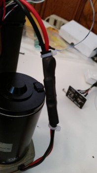
I then secured both ends of the heat shrink with a zip tie.

Fixing motor wiring

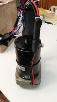
And then zip tied the newly spliced wires to the motor housing.  As I was doing this the lower (in these pics) zip tie slid off the heat shrink so I simply cut it off.

Fixing motor wiring

Here’s a comparison of the butt splice connectors: old left, new right.

old vs new splice connectors

With my repair completed, I hooked up the wiring harness, sans the AEX and with a jumper wire in place between AEX P2 connector pins 5 & 6, and hit the switch.

Ahh, sweet success!  The actuator motor came to life and up it went!

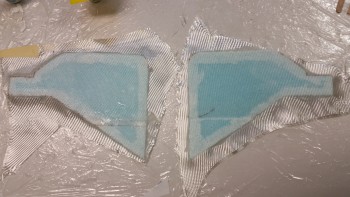
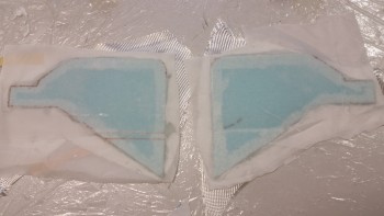
With the nose gear actuator back online, I took a quick break to unearth my layups from last night and clean them up.  I pulled the peel ply & razor trimmed the edges.  Here’s the final results.

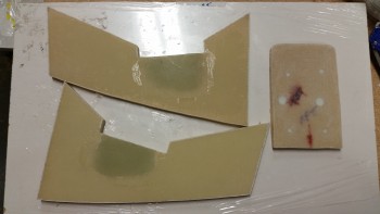
So, after some minor cleanup sanding, both BC1s are ready for install as is the draft plate. [Note: since the draft plate is simply just that, a plate to keep the cold air from entering the NG30 nose gear box, I intentionally laid it up dry.  I did this by peel plying each side but then adding very little epoxy.  Again, since this plate isn’t intended to be structural, this keeps it as light as possible.]

Round 2 glass completed

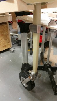
I then grabbed my tube of grease and applied a thin film to the nose wheel bracket stem before reattaching the nose wheel assembly to the NG15 bracket on the end of the gear strut.  I reattached the gear strut in place to the NG8 pivot hard points on the NG30s. Finally, I pulled out the NG3 & NG4 brackets and played around with those for a few minutes to get an idea of how they would fit (NG3 is shown on the gear strut & NG4 is sitting on the work table just to the right of NG3).

Nose gear strut with wheel assembly

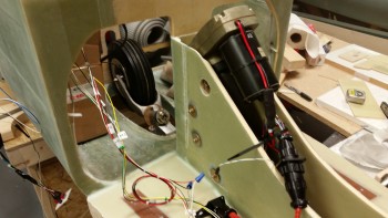
Lastly, I installed the nose gear actuator into the NG30 nose gear box and wired it all up.  I took out my ruler and did a rough measurement of around 6.75″ from the center of the NG6B attach bolt down to the center of the NG4 bracket.  I then made a small tick mark on the gear strut at the top edge of the NG4.  I clamped the NG4 bracket in place (not shown) and tested the gear going up & down.  When I ran the gear up the first time I stopped it just below the F22 channel and then raised it a few bursts at a time.  This was to ensure that A) the gear strut fit the F22 channel and cleared the sides, and B) the gear wasn’t going to crush the floor of the fuselage.

I was absolutely pleased that the wheel fit perfectly in the wheel well and that the gear strut stopped just shy of kissing the fuselage floor in the nose gear strut channel.  In addition, the front of the wheel (bottom as it sits in the wheel well) was just above the bottom surface of the fuselage by about 0.07″.  I had meant to take a pic but apparently I didn’t.

So out of the gate things were looking pretty good spacing-wise with the nose gear.  But when I cycled the gear a couple of more times I noticed that everything wasn’t looking as spiffy as it did the first time around.  And then I found the culprit.  The NG4 bracket had slipped slightly since I apparently hadn’t tightened the clamps down securely enough. No worries, I’ll finalize the gear travel later and then move onto mounting the NG3/NG4 to the gear strut.

Gear actuator motor installed

Although the gear troubleshooting was a real PITA, in hindsight I’m glad it all happened. Besides upgrading a critical failure point (apparently), I learned an immeasurable amount of information about my nose gear actuator system wiring.  Instead of just barely getting through the wiring to get it to work and then moving on to the next task at hand (to be clear: I’m speaking about me here, and in no way mean this to slight other builders!), I feel like I have a really good solid working knowledge of the nose gear actuator wiring now.

The next steps will include widening the F22 gear strut channel on the right side very slightly and then getting the gear up/down travel dialed in.  Once the gear travel is good, I’ll be permanently mounting the NG3/NG4 brackets to the nose gear strut.


Chapter 13 – Jack’s the man!

I started out today by cleaning up the layups from last night.  I pulled the peel ply, razor trimmed & sanded the edges.

Glassing Results

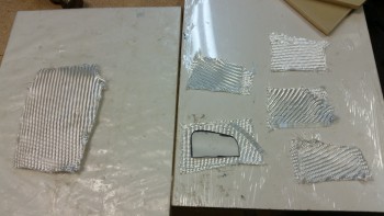
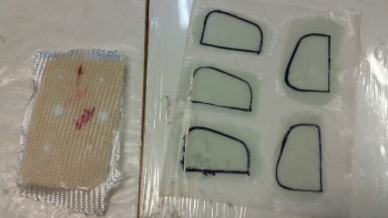
Then it was time for round two.  I cut out the pieces of BID for the other side of the draft plate and for the battery mounting tube 5-ply reinforcement pads.  I didn’t glass the face of  F4.1 since that occurs when it gets mounted to the aft side of the NG30 upright arms.

Glassing second sides

I then mixed up some epoxy with slow hardener and wetted out the BID.

Draft plate & reinforcement BID

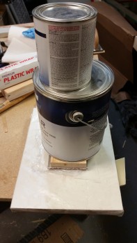
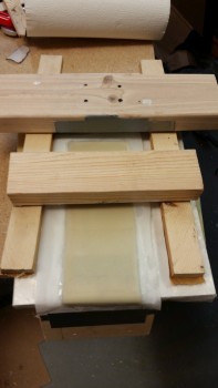
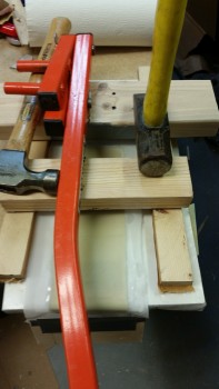
The layups followed the same flow as yesterday.  Since I wasn’t in a hurry for this layup to cure I didn’t use a heat lamp… thus I went ahead and weighed it down with a gallon of paint.

Weight for curing

Later in the evening Jack Wilhelmson returned my call.  After telling him the symptoms, he diagnosed the problem as me mixing up some wires on the switch side of the AEX P2 connector.  Sure enough, after we got off the phone I checked the wiring and had wired up the connector in the mirror image of how it was supposed to be.

Thinking that I had indeed found the problem, and then remedied it, I wired it all back up. It just so happened that the last step was to connect the AEX hot power wire to the battery.  Well, when I did I was met with a distinct & resounding “POP” sound.  Initially, I thought (and hoped) it was the 5-amp inline fuse that sounded off.  But alas, it was something on the AEX board.  I couldn’t see any physical damage but when I cracked the case I certainly could tell that I had let the smoke out of one the components by the smell.

Ok, so during our discussion Jack had told me that if no AEX unit is used then pins 5 & 6 on the P2 connector require a jumper across them.  I disconnected the AEX and then rigged up a jumper across pins 5 & 6.  I rechecked the rest of wiring, connected power and then hit the up switch.

Nothing.

It’s late in the evening now so I’ll have to wait until tomorrow to give Jack a call back and confirm both the AEX status and how to fix the persistent issue with the nose gear actuator wiring.

Once I get the nose gear actuator running correctly I’ll mount the motor into the NG30 gear box and then get the gear strut attached to the motor.


Chapter 13 – Slogamite!

At least that’s what I felt like this evening . . . (and don’t ask me what it is, just focus on the prefix: “slog” … ha!)

I had meetings and appointments today so I didn’t get back to work on the project until after 1700.

The first thing I did was to test out my new wiring connectors on the nose gear actuator.  I double checked the connections, checked the battery voltage (12.86V) and then hit the switch.  Ah, the motor came alive and down it went.  Good deal.  Then came the inevitable gotcha.  I threw the switch the other direction to raise the actuator arm and heard . . . nothing.  I double checked my wire connections, A → B, C → D, n → ∞, and all looked good.

So I tried it again.  Nothing.

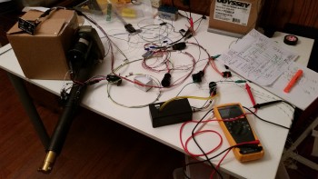
Trouble shooting actuator wiring

What ensued was about a 4 hour troubleshooting session where I did continuity checks on every single wire connection point, every run from starting terminal, through connectors, to the end connector and everything toned out perfectly on the Fluke.  I checked the internal contacts from the P2 connector to the internal contacts on the AEX board.  All good.  I recharged the battery while I went out to the grocery store: fully charged at 13.23V, and still no up travel.

I reread Jack’s directions and happened upon a point of note about damaged microswitches.  Since I now had extra I figured it wouldn’t hurt.  When I started removing the microswitch on the right side facing the front of the unit, after marking its location of course, it literally crumbled in my hand.  Not sure why that happened, but I replaced it.  The good news is that I was able to reuse the lever arm from the newly deceased switch on the first switch body that got sucked into the ‘actuator of destruction’ and lost its lever arm.  So I’m still down only one micro switch, but unfortunately the switch replacement still had no affect on the actuator being able to return to the up position.

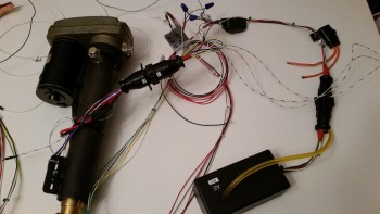
P1 & P2 connectors connected

Having exhausted every troubleshooting technique, and checking, double-checking and triple-checking every connection and continuity of wiring, I figured it was time to punt.

I’ll call Jack tomorrow to figure this thing out.

I took a break in the middle of the nose gear actuator troubleshooting saga above & spent about 15 minutes cleaning up the peel ply snots and edges of the right floor pan layup.  Now both floor pans are ready for next steps.

Right side nose floor cleaned up

Later in the evening, and I do mean late, with a fair amount of frustration with the nose gear actuator, and weary of chasing electron phantoms and wire ghosts, I decided to roll up my sleeves and at least get something glassed and curing so the night wasn’t wasted.

I turned my sites on the backside of the F4.1 (old F6) mini upright bulkhead that gets mounted to the aft side of the NG30 uprights.  Although I keep wanting to write “aft,” I say “backside” because the side I’m glassing is not visible once glassed but actually faces forward.  The F4.1 gets a 2-ply BID layup, and I’ll be adding two approximately 1″ wide strips on top and bottom as reinforcements for the velcro slots that will be used to mount the Radenna SkyRadar-DX ADS-B IN receiver.

Also on the list are the BC1’s, which are really a continuation of the NG30s into the forward battery box area just foreword of the F1-3 bulkhead (Napster).  Since I will be mounting a retractable heated pitot tube, I had to mount the battery in a very specific location.  This means that securing the battery will not possible in the usual Long-EZ fashion of simply strapping it to the nearing bulkhead.  In the original plans that was a big function of the F6 bulkhead, since the battery was located immediately aft of F6 and was merely strapped to it.

My battery, for lack of a better description, will be out in free space.  To ensure it stays in place I’ll be using a 2″ wide military grade web strap with a metal clasp and about 6-8″ of Velcro that will wrap around the center of the battery, holding the battery to the BC1s. But how you say?  I will have a metal tube that is mounted between the BC1s, right under the battery.  Since the tubing is clearly strong enough to hold the battery in place, I just need to ensure that the BC1’s are strong enough.  Thus, I’ll be adding a 5-ply BID pad to both the inboard and outboard side of each BC1.  The outboard glass will never get disturbed once glassed, while the inboard sides will be drilled to the diameter of the metal tube along with the BC1.  In addition, I’ll have a thinner version of this type strap running around the battery from side-to-side.

Glassing NG31s hardpoints & NG4.1

In preparation, I used some pulled peel ply from the floor pans to make up a small template for the 5-ply BID pads.  I cut 10 small scrap pieces of BID and stacked them 2 plies deep in 5 stacks in a prepreg setup.  I also cut 2 plies of BID for the backside F4.1 layup.

BTW, the 5-ply BID reinforcement pads are shaped the way they are to not only reinforce the battery mounting cross tube, but also to allow room for the center H100 foam piece that will get mounted in the channel between the BC1s, just below the 5-ply pads.

Glassing NG31s hardpoints & NG4.1

I mixed up some epoxy with slow hardener and wetted out the F4.1 layup and the prepreg BID.

Glassing NG31s hardpoints & NG4.1

As you can see, I continued to wet out the F4.1 layup while also using my template to mark up the 5 sets of BID for the reinforcement pad on the outboard BC1s.  [Note: Since the F4.1 is H100 foam, I didn’t use micro to prep the surface since the foam is so tight grained it merely laughs at micro).

Glassing NG31s hardpoints & NG4.1

I cut out the 5 BID pads for the BC1s.

Glassing NG31s hardpoints & NG4.1

I continued to work the F4.1 layup making sure it was completely wetted out in-between the different steps on the BC1 BID.  After applying a thin layer of epoxy on each layup area on the BC1s, I then laid up the BID pads one by one on the surface of the BC1s where the battery tie down tube will get mounted.  I split the last 2-ply BID prepregged pad for the fifth and final ply on each BC1.

Glassing NG31s hardpoints & NG4.1

I then removed the final top piece of plastic on the 5-ply BID pads.

Glassing NG31s hardpoints & NG4.1

I added the approximately 1″ x 3″ reinforcement ply both top & bottom on the F4.1 and also peel plied the BC1 5-ply reinforcement pads.  I applied the peel ply a little wet since the 5-ply BID pads are thick and I wanted a good smooth transition between the pads and the original surface of each BC1.

Glassing NG31s hardpoints & NG4.1

I finished wetting out the F4.1 reinforcement pads and covered the BC1 assemblies with plastic Saran wrap.

Glassing NG31s hardpoints & NG4.1

I then cut a piece of peel ply from my roll of peel ply and began to prep it for F4.1 by taping a 3/4″ block of wood to the end of it.  This wood will serve as a weight to keep the glass conformed to the curved bottom end of the F4.1.  [Note: The reason the bottom of my F4.1 plate is curved is because I rounded all the corners on my NG30s to minimize any potential stress points, and because I’m just damned fancy . . . haha!]

Note that I have the F4.1 work piece sitting atop the BC1 assemblies.

Peel ply for backside of NG4.1

Below is the peel ply applied to the F4.1.  I taped it on the top side with the weight pulling the glass over the curved surface on the opposite end (nearest the camera).  The block of wood is not very heavy of course, but it is just enough to keep the glass conforming properly (read: “attached”) to the curved bottom end of F4.1.

Glassing NG31s hardpoints & NG4.1

I then careful stacked some blocks of wood around the F4.1 layup.

Weighing down NG31 hard points

And added a few heavy items to weigh down the 5-ply BID pads laid up on the BC1s. Now, I didn’t use something bulky like a gallon paint can to weigh this thing down because I wanted it open so I could aim a heat lamp at it without all my heat rays getting blocked.

Weighing down NG31 hard points

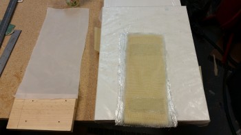
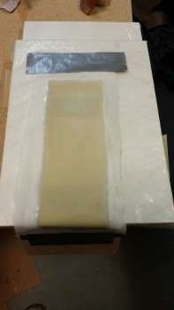
Since I had a good little bit of epoxy left over, and I hate wasting epoxy, I grabbed some foam out of my scrap pile to make up a small 3″ wide by 6″ long 1/4″ thick “draft plate.” This plate will sit immediately above the NG6B nose gear pivot and will keep the cold draft air coming in to a minimum.  My buddy Marco came up with the idea and since it’s a good one, I’m copying it!  You can check out his version of this here.

Nose gear actuator box draft plate

This is regular 1/4″ PVC foam, so I micro’d it with slurry and then filled in the holes with thick micro.  I then laid up 2-plies of BID, and since it will be getting glassed into a very tight spot between the NG30s I peel plied it so that it I could have BID tape coverage anywhere I needed as I attach it.

Nose gear actuator box draft plate

Tomorrow I’ll call Jack Wilhelmson and figure out the issue with the nose gear actuator.  I also plan on finishing the right side nose wall piece.  However, I’m not going to glass in the nose side walls until I get some other tasks crossed off the list since I want to have easier access to the internal nose areas without two big side walls staring me in the face.