Today has been a long time in the making. As most anyone who knows me will attest, I tend to be a planner. Grant it, not always the best but I do try to keep the wheels in motion so that I least have all the parts, pieces, components and/or systems at the ready when it comes time to implement the plan. Well, today has been the culmination of a year+ journey into the realm of both machining and CNC, and the first step in making that capability a reality.
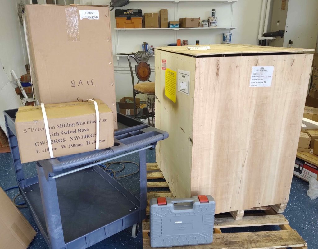
The big truck arrived today with my Precision Matthews PM-30MV Milling Machine, Stand, Vise and accessories. As you can see, it’s one big bubba. Here it is sitting in my new garage in NC.
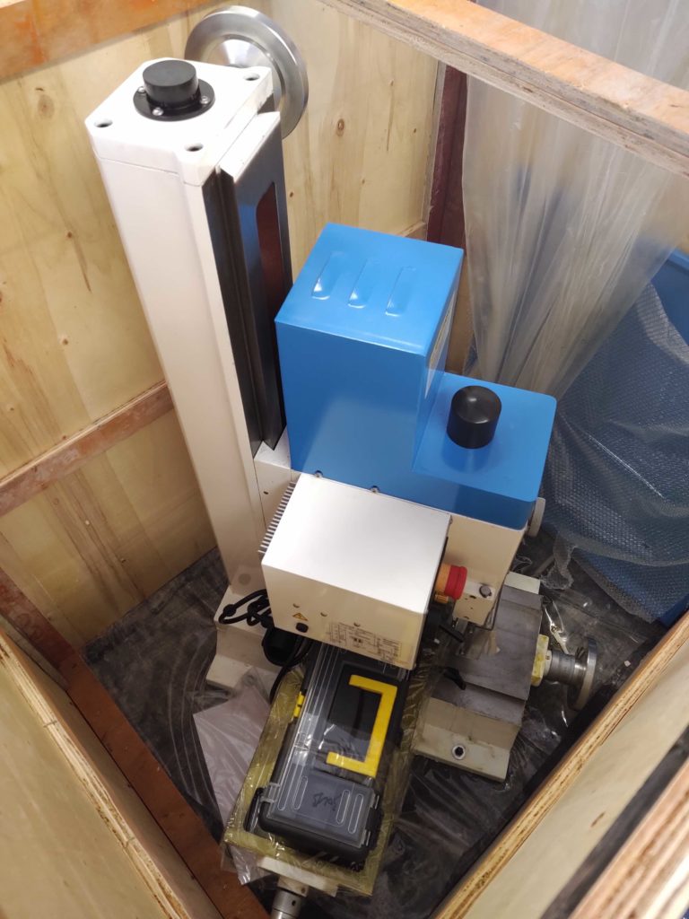
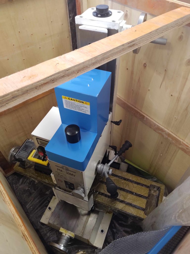
Here’s a couple shots of the actual mill in the crate, which I’m leaving it in until I’m actually ready to install it in the workshop with it up and running.
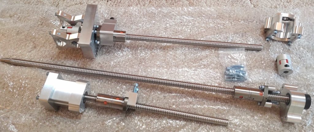
I was also able to coordinate my purchases with Dave of ArizonaVideo fame for his work in machining the CNC Ball Screw Kit required to convert this mill into a CNC machine. I pulled the trigger on the CNC Ball Screw Kit from Dave about a month prior and both the kit and the mill arrived within a week of each other.
As you can see Dave did a great job on making this kit, and specifically machined the motor mounts on this kit to accept my Nema 34 stepper motors.
I won’t get around to sinking my teeth into the machining portion of my build for most likely another few months, but having the components on hand allows me to ensure I configure the shop appropriately to allow for cramming all this equipment into it while still having room to build the plane!
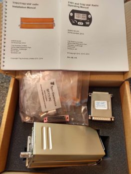
Today UPS delivered the last piece of the puzzle Avionics-wise for my Long-EZ from Aircraft Spruce: my COM 2 radio:
Specifically, the Trig TY91 VHF Radio.
As with nearly all decisions for this build, I had originally targeted the Trig TY91 as my COM1 radio, with the GPS radio as the COM2. Then the way the radio swap circuitry had to work, in conjunction of my going with the Garmin GNS-480 for my GPS unit… and due to the 480’s phenomenal COM radio functions, I decided to go with the GPS as my COM1 and the HXr controlled radio as my COM2.
With my COM1/COM2 radio selection made, for cost (and weight) reasons I then decided to go with the remote REM760M radio as my HXr-controlled backup COM2 radio. However, they apparently stopped producing them and GRT Avionics stopped selling them so I was driven back into the arms of the Trig TY91…. more expensive, and a few ounces heavier, but by all accounts definitely a superior radio.
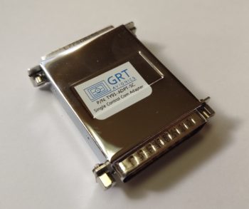
Moreover, with the Trig radio I then required a serial adapter from GRT that allows the HXr EFIS to control the radio functions. Pretty cool in my opinion, as again it frees up panel space with the actual radio unit (above) being shoved into just about any available open spot in the plane (I plan to mount mine on the the top avionics shelf of the Triparagon).
One glaring oversight in my planning out the panel components with both HXr EFIS controlled Trig components –this radio and the TT22 transponder– is that I failed to take into account the considerable 2″ length of their respective serial adapters. Two inches may not seem a lot in the normal world, but behind my Long-EZ panel, where some clearances are just over 1/8 of an inch, it matters!
So much so that I have been considering a swap-out of the TruTrak 3-1/8″ ADI due to its depth and overall space it occupies. I’m more than happy with the functionality of the ADI, but it is a space hog in the tight quarters that is the reality of my avionics/instrument bay. More to follow on that later.
I was quite tired from this last trip so I decided to “take the day off” today, take it a bit EZ and do some CAD work.
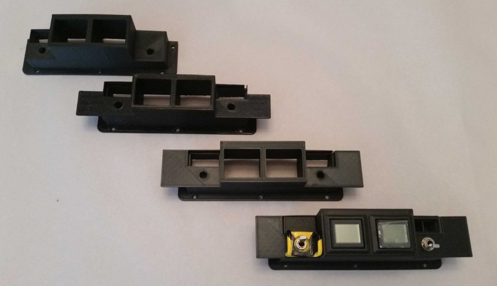
I started off by updating my Warning Annunciation Sub-panel to bring the face of it further out from the panel. I then 3D printed the new version 4.
To show you the design machinations, here’s a shot of all 4 variants so far. As you’ll see later below, I’m now on version 5.
The reason for this new added sub-panel depth was that I checked the visibility of the warning sub-panel while I was sitting in the cockpit with the canopy closed (probably a good thing to check eh? …. actual flight configuration?!) and realized that the top edges of the AG6s were obscured from the canopy skirt and the angle that I view it from. Also the top 2/3rds of the embedded Korry indicator lights were obscured as well.
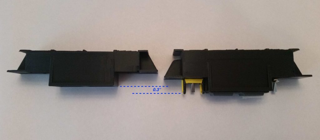
So I added 0.3″ to the back side of the sub-panel to bring it out to the very edge of the glare shield so I could see it fully with the canopy closed. Now only less than the top 1/3 of the Korry indicator lights will be obscured while the AG6s will be fully visible.
Here’s a top-down view showing the depth difference between version 3 and version 4.
While Subpanel version 4 was busy in its nearly 7 hour 3D printout, I updated the panel with a ton of minor tweaks.
Shaved 0.040″ off each side edge so panel won’t cut into sidewall from vibrations.
Notched the upper right corner at underside of longeron — for cable routing.
Moved the ALT Static switch to the upper RH corner (not sure if I’ll leave it there).
Moved RAM air & oil cooler louver adjust rockers to left of fuel pump switch (LLHS).
Re-situated the 4 top row CAMLOCs for the Aft Nose Cover mounting
Re-situated the 2 top panel screws.
Lopped off bottom center strut leaving just a hint of the curve for aligninment.
Added 2x 1/4″ holes to mount modified diamond RAM ball mount for my iPad Mini (via moving the RAM air and oil cooler rockers from the lower center strut to LHS).
1/4″ RAM mount bolts will also serve as panel mount bolts on lower center strut.
Moved on/off indicator lights dimmer to account for the warning sub-panel width.
Moved gear/canopy warning LEDs to account for the warning sub-panel width.
Verified distance between Circuit Breakers and right armrest top.
One last task left to do is to shave about 0.020″ off the upper LH “corner”… something that with all my changes this curve mod will be a bit trickier to accomplish.
I also moved the panel’s Push-to-test button for the on/off indicator lights to mount on the right side of the Warning Annunciator Sub-panel in order to get that small push button off of the panel and out of the way [it’s a pain to mount because it’s so small you have to dig out a bunch of original panel to get it mounted].
This of course resulted in Version 5 of the Warning Annunciation Sub-panel… same as V4 except for the mounting plate I created on the right side for the Push-to-test button.
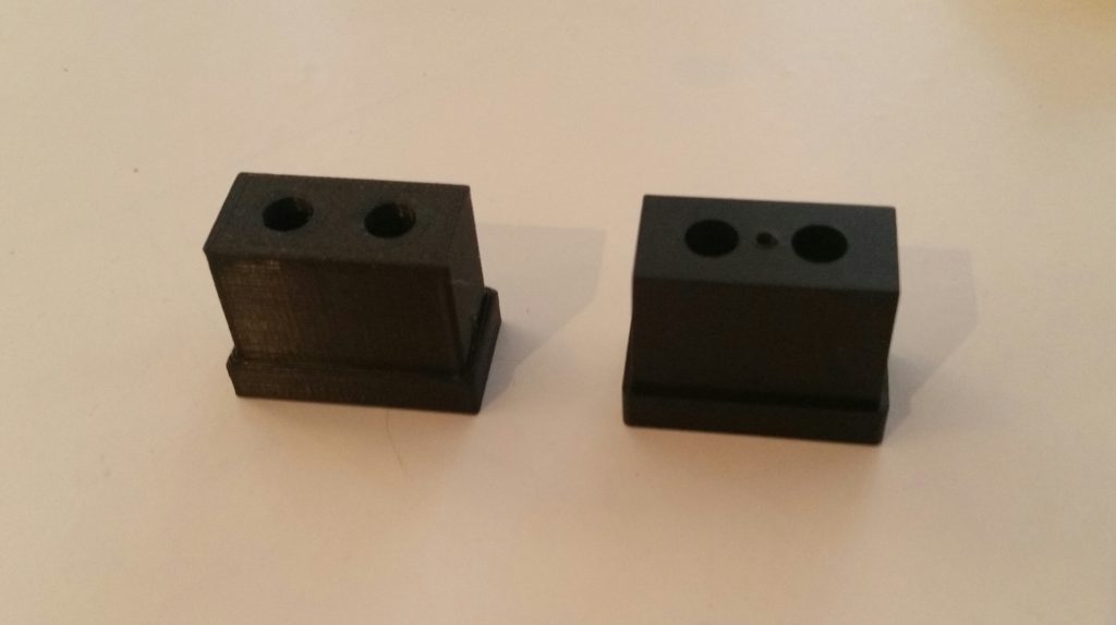
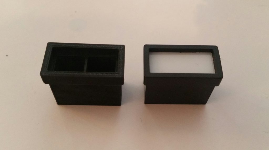
For my last hurrah of the evening, I took a solid Korry light mockup that Marco had drawn up in Fusion 360 and turned it into a hollow, functioning Korry light case and then 3D printed it (on the left):
This will allow us to print these light cases in case we need one a spare. I’m also working on the lettered front plate process to be able to make a complete light unit to customize as required.
For the right side of the warning sub-panel I split the case (below left) in the interior to allow for two different colored annunciator lights to correspond with the two different states that my single switch will manipulate (B/U ALT & E-BUS PWR).
I’m very happy with how the panel stuff is coming along. Of course I would rather be flying this bird, but taking the opportunity when I’m not physically building to tweak it as I mentally armchair fly it should have it very close to its final & optimized configuration before first flight!
Unfortunately, this means getting back to work on the house to finish prepping it to sell versus the few hours I got to work on the plane build today before I left out for home.
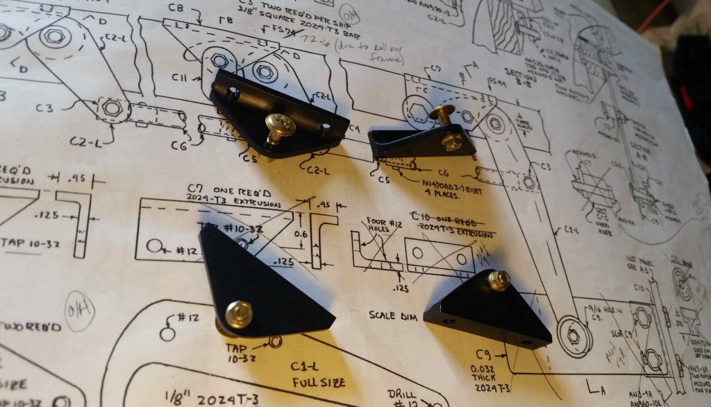
I started off today in a failed attempt to follow the plans in using Bondo (aka “Builders Bog”) to set the C8 latch plates in place on the canopy hard points. I don’t know if the Bondo was too old or if the C8 surfaces were too smooth and shiny for bonding, but being in transition meant I had no Acetone or accessible mineral spirits to clean up the C8 edges for bonding.
Wanting to get these canopy tasks moving forward, I simply crawled into the cockpit and set the C8s in place one-by-one as I marked where they needed to be attached with a finer-tipped Sharpie. I then held up the C8 to its respective outline, adjusted for the Sharpie line width and then marked the holes for drilling.
I will point out that my C8 install is unlike the plans steps where you Bondo the undrilled C8s to the canopy hard points, then drill through both the attached C8 and canopy hard point in one step, to later then drill out and tap the C8 mounting holes. My install is different since I’m using Jack Wilhelmson’s Canopy Latch Kit which included predrilled and pre-tapped C8 latch pieces.
To ensure my alignment both in drilling the C8 mounting holes correctly spaced and C8 alignment in relationship to the C2-L latch hook –including proper clearance with the longeron– I started each C8 install by drilling one hole, setting the C8 in its proposed spot, climbing into the cockpit to check clearances & alignments, then remarking before drilling the second and final hole.
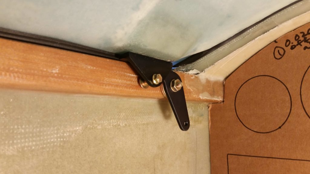
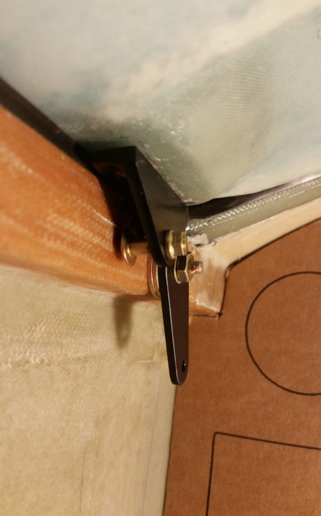
The C8 mounting placement on the #2 canopy hard point (just forward of roll bar frame) sits just under the actual embedded canopy edge, which leaves me no option to place the mounting screws either on the inside of the frame as I did with the aft two C8 latch plates (#3 & #4) below, nor on the external side of the canopy frame as I did with the very front latch plate (#1) . . . [Sorry, no pics this time of the exterior holes on #1].
I’m not surprised on the improvised method I’ll need to employ for C8 latch plate #2 install, since incorporating mods on an already-modified pseudo-French canopy install is going to call for some unique, out-of-the-box processes to complete.
The #2 C8 latch plate will thus get mounted by pre-mounting threaded pins to the C8 mounting holes and then floxing those pins and the C8 into place inside 2 holes drilled into the canopy hardpoint, much as we do on many other components of the build (elevator hinge plates, baggage pods, etc).
I have to say that I’m very happy with how the canopy hard points worked out for the aft pair of C8 latch plates spacing and configuration-wise.
My improvised method worked fairly well with only a couple minor SNAFUs.
First, with no proper drill bits on hand I stopped off at Harbor Freight and picked up a cheap set of bits. I mean, after all, I’m only drilling through fiberglass and foam. I have to say this was the worst purchase I’ve made at Harbor Freight, having used numerous drill bits from there before. I broke 2-3 drill bits literally within the first few minutes, and unfortunately one of these was in the forward hole on the #3 canopy latch hardpoint.
As frustrating as it is, I’ll have to punt on this #3 C8 install (below) and drill the broken bit out later with a good quality drill bit . . .
In addition, somewhat analogous to the countersunk screws required to attach the canopy frame to the canopy hinges… and my not having the correct lengths on hand when I needed them, so too did I not have all the correct lengths of button head screws required to install the C8 latch plates (again, this is not a standard plans canopy install). As you can see below I improvised with some AN bolts/screws I had on hand as I await the menagerie of button head screws to arrive from ACS.
Beyond some minor logistical and qualitative tool challenges, getting these C8 latch plates’ mounting locations nugged out was a big step. As with most things on this build, doing the initial install in any given area begins the iterative process of flushing out all the further required steps in acquiring correct parts, redos/repairs and prerequisite data collection for subsequent tasks.
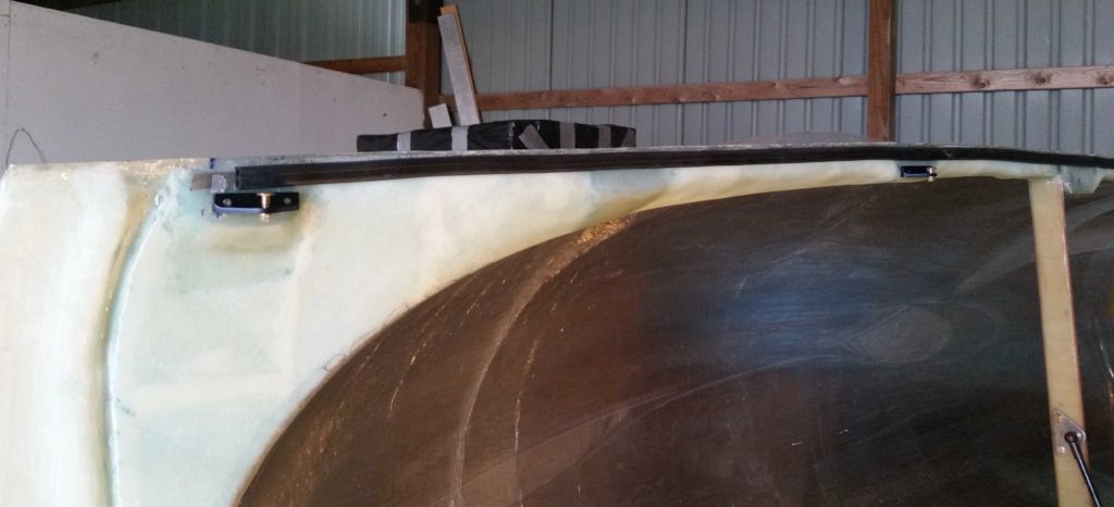
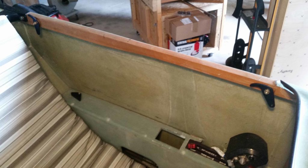
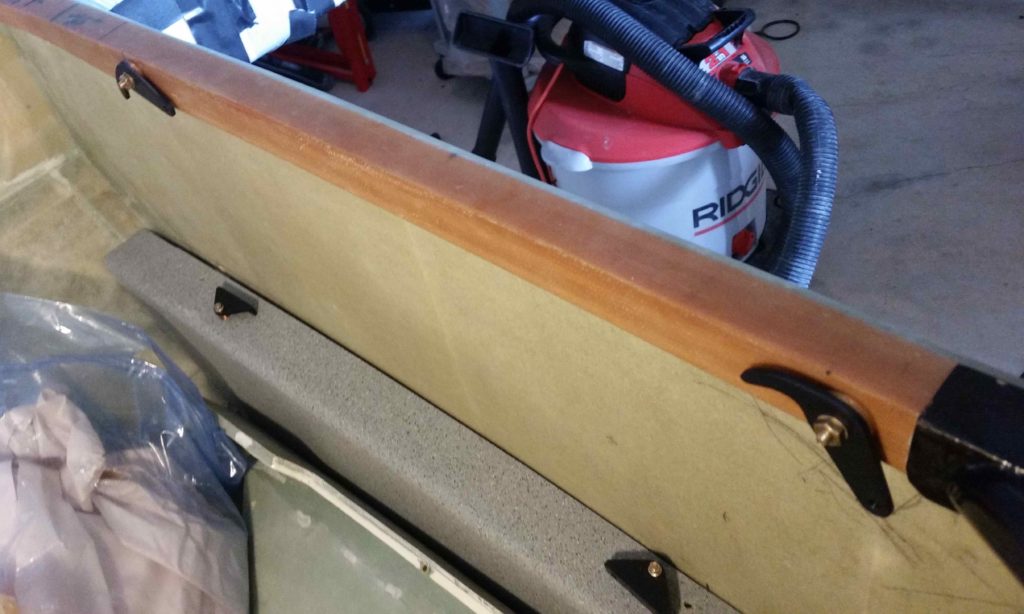
Here we have the aft pair of canopy C8 latch plates in place.
And here’s a shot of the #1, #3 and #4 canopy C8 latch plates in place.
Besides working on the canopy, I also performed some troubleshooting on the HUD with GRT Avionics’ tech, Mark, over the phone. Turns out there is a short somewhere in the system so I’ll be returning the unit so they can take a look at it and either repair it or replace it with a new unit.
Alas, this is the last of my plane building for at least a good 3-4 weeks. I will be working on some CAD drawings and possibly 3D printing a part here or there over the next few weeks, but my priority again will be on the house to get it on the market.
Today I again focused mainly on the canopy latches to get them as far along as possible on this trip.
I started off by gathering up all the actual C2-L latch hooks, thin washers and standard nuts (to allow for removing the C2-L assemblies when it comes time to paint the longeron) and installing them onto the left longeron.
Here we have the front set of C2-Ls…
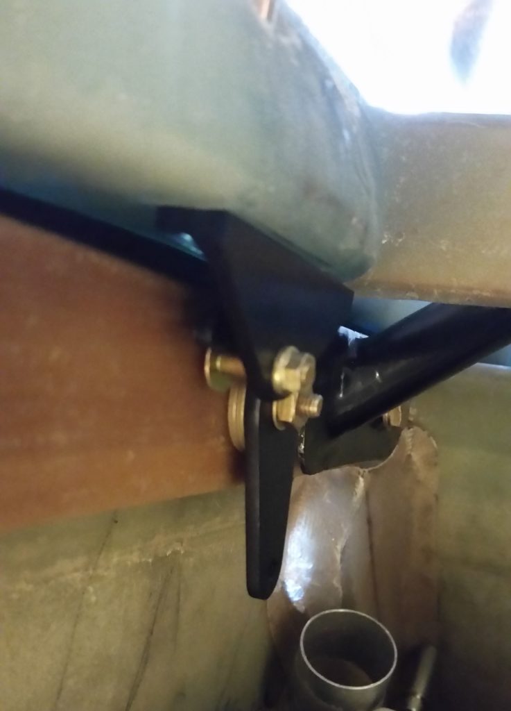
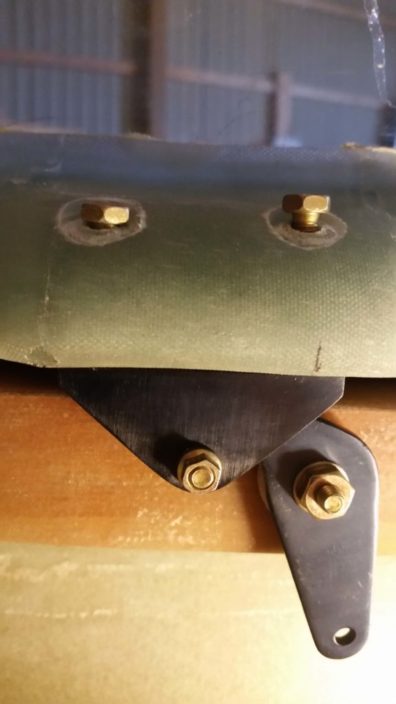
And below is a shot of the aft pair of C2-L latch hooks in place. As I mentioned in my last post, I had to swap out the AN3-13A bolts for AN3-15As for the aft two C2-L latch hooks since my longerons are about 0.3″ thicker from the front seat aft. With the bolt swap out the aft C2-L latch hooks, washers and nuts fit spot-on.
With all the C2-Ls in place I then measured the distance between all the latch hooks to determine the required lengths of the connecting tube segments that will link all the C2-L latch hooks together to be actuated simultaneously by the canopy latch handle.
I also took the opportunity to inventory all the parts I have on hand in an attempt to ensure that I have what I need to connect up the canopy latch system… unfortunately I don’t and will have to acquire/make a few parts. NOTE: Remember my canopy latch setup is a bit different than the stock configuration.
I then got busy assembling the 4 canopy-side C8 latch catches.
If I have time, tomorrow I’ll Bondo the C8 latch catches in place and then drill out the initial holes for their respective mounting screws.
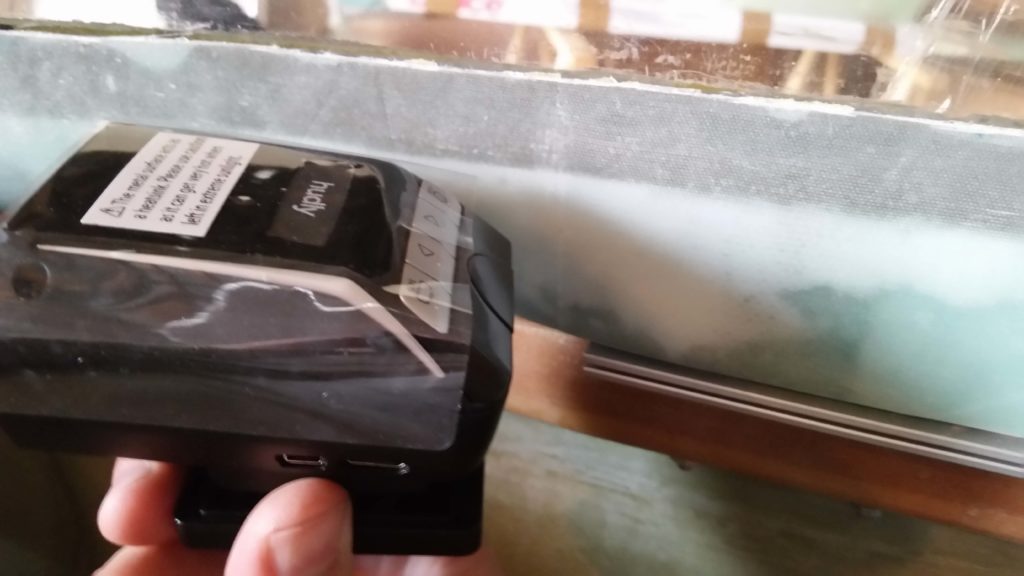
In addition to the canopy latch assemblies I also attempted to fire up and test out the Hudly HUD system. Unfortunately, I’m having an issue with the glass fuse in the cigarette lighter power adapter that keeps blowing and thus preventing me from testing the configuration of the HUD components. I’ll contact GRT Avionics and try to troubleshoot the issue.
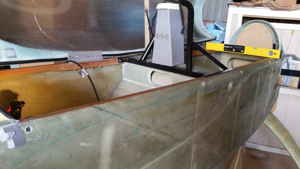
Today I finally got back on the build a bit by determining where my canopy latch hooks (C2-Ls) will get mounted to the left longeron.
I started by determining the alignment of the canopy latch hook attach points on the canopy side, then marked the associated C2-L AN3 bolt positions on the longeron.
After marking the canopy latch hook attach point locations at the respective Fuselage Stations, I then measured the required 0.6″ down from the top of the longeron at each canopy latch hook attach point and marked a crossline to identify the spot to drill.
I then drilled a small pilot hole at each canopy latch hook attach point location from the interior outboard and then drilled each pilot hole out further to 3/16″ diameter.
From there, I drilled each hole with a 1/2″ drill bit from the outside in to clear out the foam at each hole and create an opening in the glass skin to allow clearance for the AN3 bolt heads.
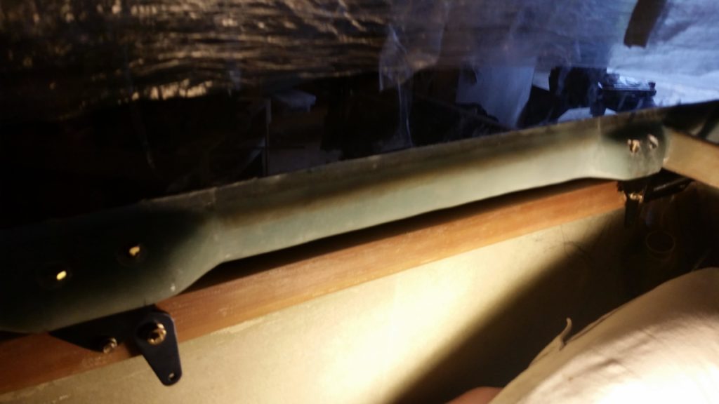
Now, you may have noticed that I have 4 canopy latch hooks –2 forward and 2 aft of the pilot’s seat– versus the 3 called for in the plans. The reason behind my using 4 canopy latch hooks is simply to keep my significantly oversized canopy nice and secure during flight. Moreover, my rollbar longeron mount messes with the original plan’s location of the middle canopy latch hook and required me to move it forward to avoid the rollbar mount. This left quite a gap between the middle and aft canopy latch hook assemblies, so I added a fourth canopy latch immediately aft of the rollbar mount.
Below are the aft 2 canopy latch hook attach points with the AN3-13A bolts and 2 each AN970-3 washers in place. Since my longeron is about 0.3″ thicker from the front seat aft, I’ll need to increase the length of the aft bolts a bit longer than the current AN3-13As.
And here we have the forward 2 canopy latch hook attach points with the AN3-13A bolts and 2 each AN970-3 washers in place.
Finally, here’s a shot of the very forward canopy latch hook in place at the plan’s position, F.S. 44. Of course, this canopy latch hook is definitely not per plans either since I’m using a very different canopy latch handle than the stock version.
During this trip down to NC I’ll try to knock out the longeron side of the canopy latch setup and prep to finish the canopy side latch assemblies on my next trip down.
In trying to lean forward as much as possible on the build, without of course having it on hand locally to build, I went ahead and pulled the trigger on the Hudly HUD unit from GRT Avionics.
Having the HUD on hand actually helps immensely in my planning because I’ll need to have access through the aluminum instrument panel to run a couple rather thick wires from behind the panel to the HUD projector unit that I intend to mount somewhere along the right longeron (see below).
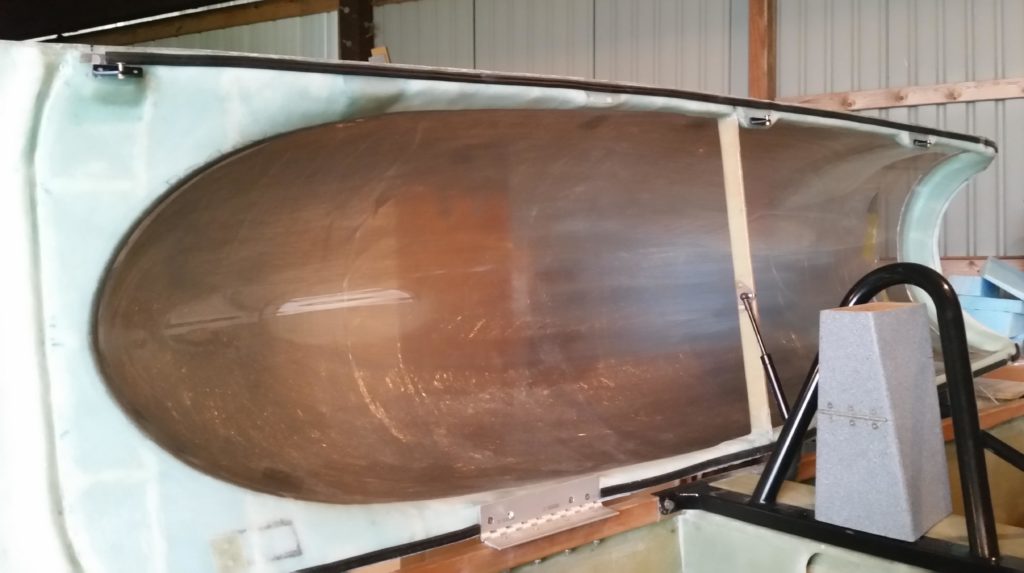
I had the HUD unit sent to my friends’ house in NC, so I was a bit concerned when I first looked at the components that the combiner screen (below) might not fit well inside the canopy. However, the screen fits fine and looks like I’ll be able to align it well with my field of view, but I will need to create a sharper angle for the mounting tab to secure it at the correct angle for good viewing.
I then played around with the projector unit and tested out possible locations where I could mount it. The optimum location for me would be right at the front edge of the forward canopy hinge.
However, when I measured the distance between the projector face and the combiner glass screen it measured around 16 inches. By looking at the mounting template provided by Hudly I could clearly see that their idea of a proper distance between the two was less than 8 inches.
I confirmed my concerns with Greg at GRT Avionics and we discussed possible solutions to optimize the install of this unit. However, there may be a possibility that this unit just won’t work well with the configuration of the Long-EZ and I’ll have to send it back . . . I’ll see how the mounting configuration plays out early next week by firing up the unit and testing out the actual image.
Overall, I’m very pleased with the location and configuration of the screen, I just need to ensure that I can deliver a good image to it to actually get the HUD unit to work as designed.
On my latest trip to North Carolina I was able to stop by Marco’s on the way down, spend some time with him and his Long-EZ at his hangar, and then attend a local EAA meeting.
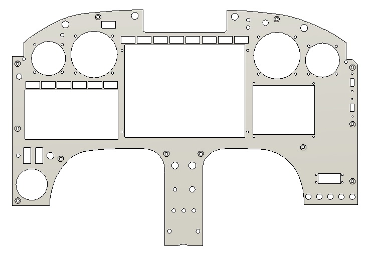
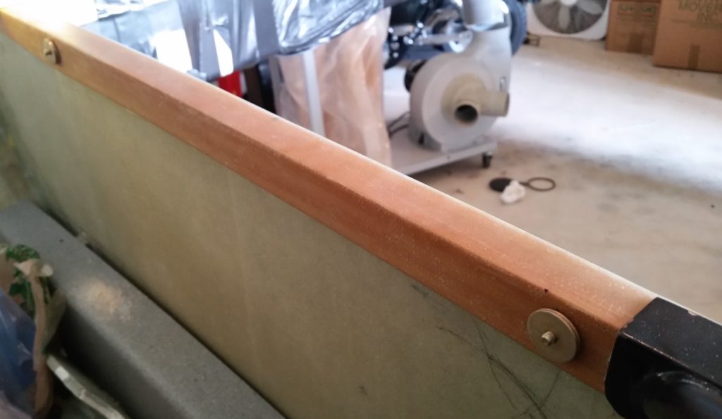
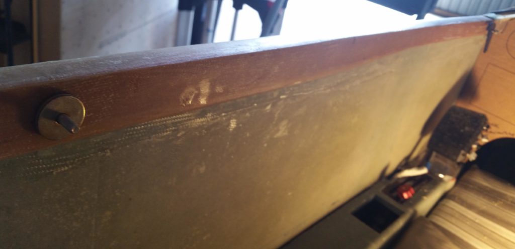
The next day (today) Marco and I printed out the latest cardboard version (#3) of my instrument panel before I left for my NC hangar.
After unloading all the hangar stuff from my load I then quickly cut out the perimeter of the cardboard panel mockup to test fit it in place. Note that I didn’t cut out any of the internal area to ensure the panel was as strong and rigid as possible for the test fit.
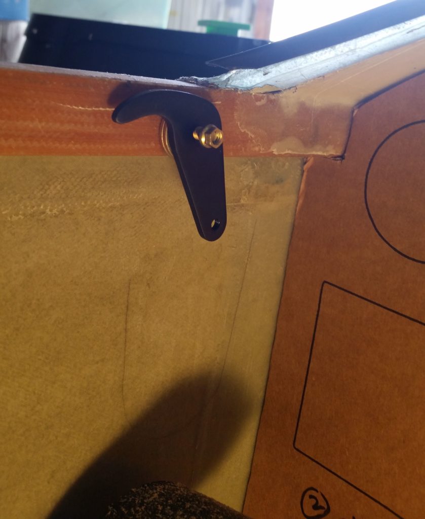
The cardboard test panel fit well, but it still needs just a couple minor tweaks: shaving off about 0.020″ on the upper left edge and also shaving about 0.050″ off each vertical edge. I also need to assess clearance between the lower corners on each side of the panel with the respective armrests and switches.
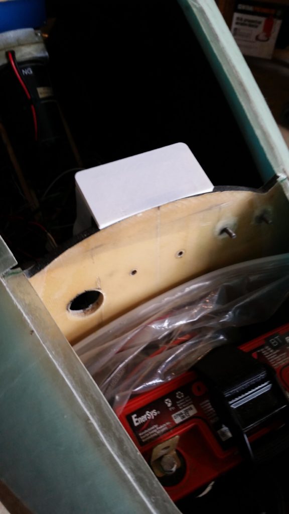
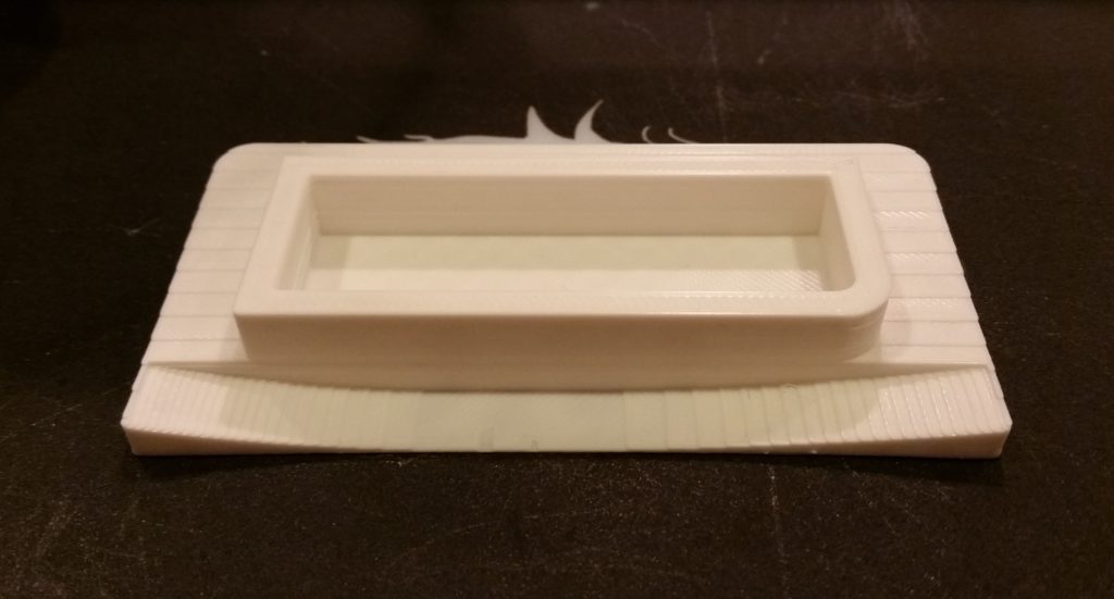
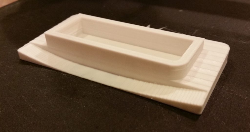
I then quickly popped in the version #2 of the NG-30 cover that covers the open hole between the NG-30 uprights, the aft bulkhead and the Napster bulkhead.
This latest NG-30 “hole” cover fit much better than the last one and best of all, it doesn’t interfere with the nose hatch closing in place.
With two of my primary checks out of the way, I then departed the hangar and unloaded the rest of the stuff into my storage unit.
Wiith no real building going on I’m back in the planning and collecting stages.
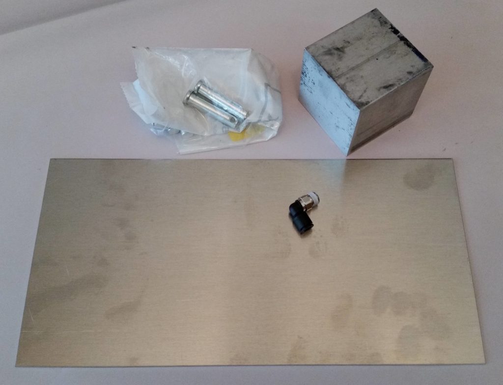
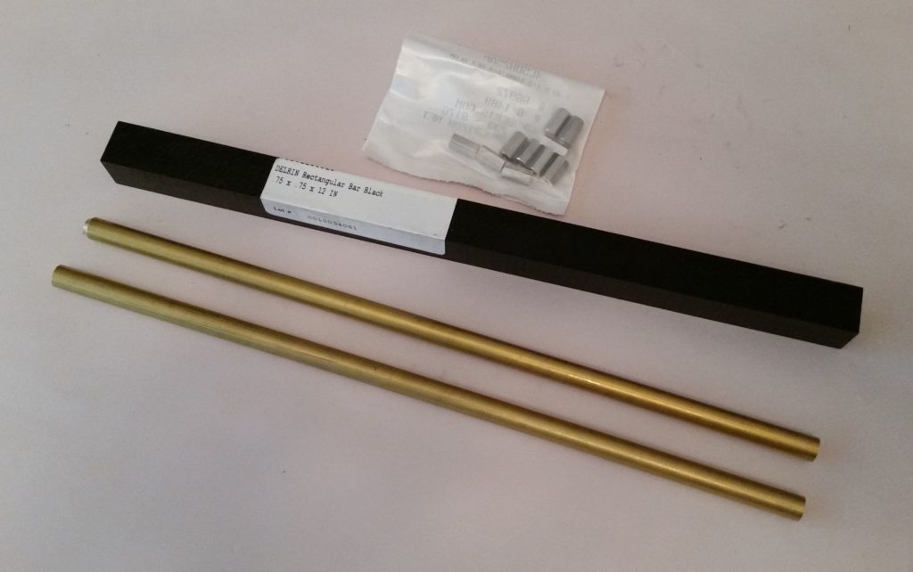
So first off, some “tooling up!” . . . in the last few days I picked up almost the last of what I need for the Milling Machine pneumatic drawbar and lathe CNC conversion (again, the primary purpose for all this is to make components for the plane):
In addition, I picked up the 2 brass bars that I’ll lathe into my aft nose cover-securing hinge pins. Also got some black phenolic for my canopy cam latch to help keep the right front corner of the canopy tightly secured during flight.
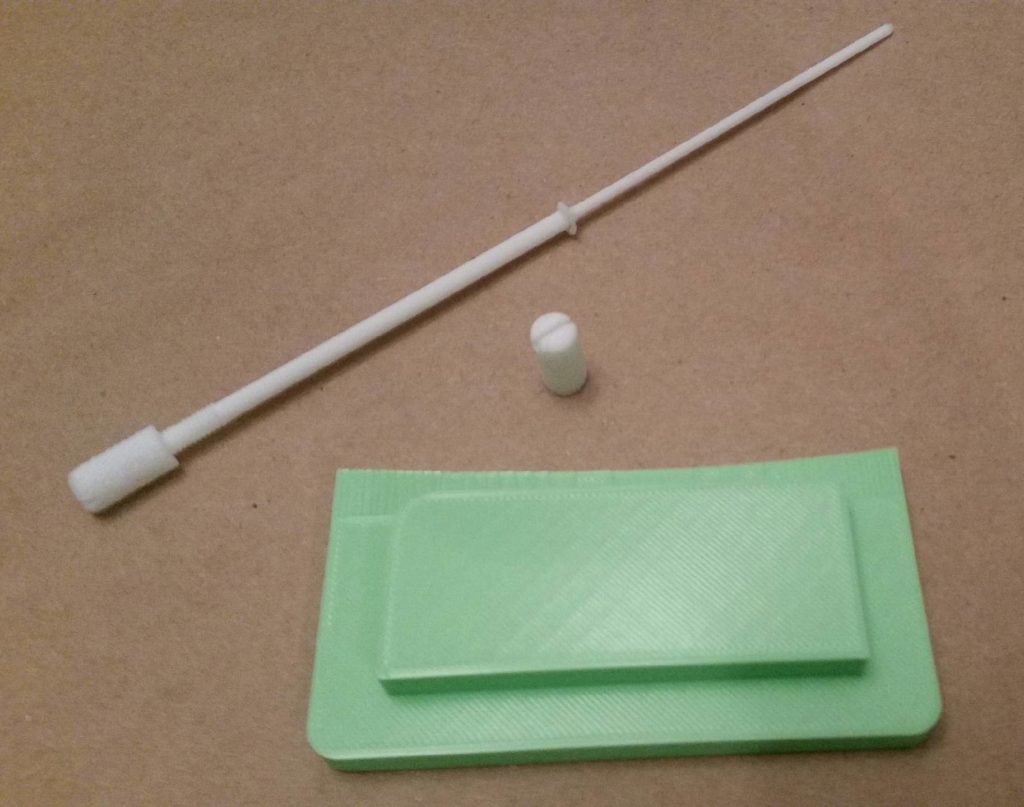
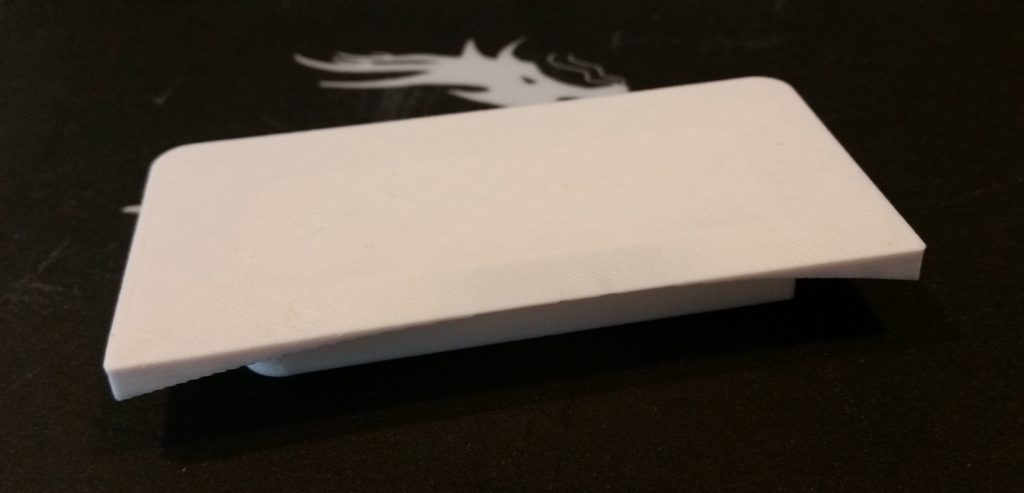
As a reminder, I 3D printed a mockup of an aft nose cover-securing hinge pin… the long white thing in the pic below. I checked it out and assessed it on the actual plane during one my trips to the hangar, and giving the design a thumbs-up I then bought the brass stock.
I’ll also note that since I highly suspect that a LEZ labeled box(es) containing the AN3 bolts, aircraft grade nuts/hardware, and 6061 aluminum panel stock must be buried deep in the bowels of my #2 storage unit (e.g. not accessible), I pulled the trigger on some more hardware and 2′ x 2′ piece of 0.090″ thick 6061T6 instrument panel stock from ACS.
Finally, I know this type of update isn’t momentous or awe-inspiring, but I post these to show that although I’m not full-on active on the build, I am still working it in every way possible. I’m sure many of you have observed seemingly very active and motivated airplane build projects fall off into the chasm of oblivion, never to pop back up on radar again . . . just want to ensure folks that that’s not happening here!
As I mentioned in the last post, I wanted to get my 3D printer (“Bob”) back to work. I really like the idea that while I’m working on the house getting it ready to sell, I can have Bob hard at work concurrently making stuff for the plane build, machining CNC conversions or just for fun.
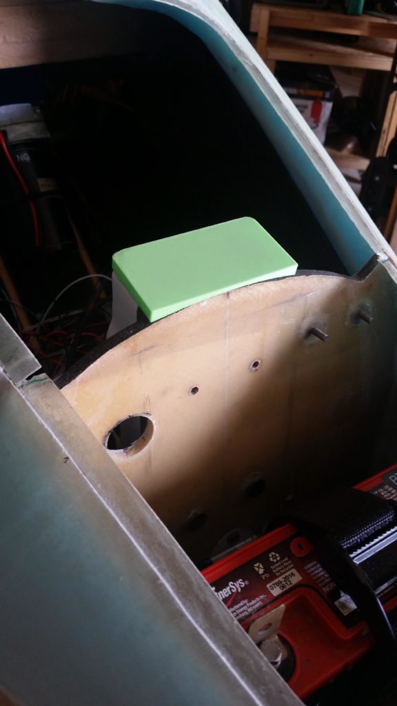
To get some airplane production rolling [albeit mostly cosmetic], I decided to spend an estimated 45 minutes updating the Fusion 360 CAD file for my NG-30 upright/Napster bulkhead cap, the initial version (green) shown mounted in place below during my last trip to the hangar.
I of course planned on there needing to be multiple revisionary updates for this top cap since there a number of angles and a major curve involved.
And not surprisingly, my 45 minutes turned into almost 2 hours . . . oh, well!
Nonetheless, I persevered and was rewarded with a hard fought version 2 of the NG-30 upright/Napster bulkhead top cap.
If you compared the 2 versions, you’d see that I did in fact drop the overall height of this top cap down 0.15″ to provide some required clearance with the nose hatch cover.
I did about 5 other tweaks, including bringing the front corners forward about 0.020″ while leaving the center at the same dimension. This then requires the major upside “U” curve already in place, and then another very minor, shallow curve from the top looking down from each corner aft 0.020″ to the original center plane on the front edge.
I also dropped the back edge down 0.100″ while leaving the front edge the same height. This required an angle on each side… you can see the rough steps –from the draft quality 3D print– of the resulting side angles in the pics above.
It will be interested to see how this version fits, and much like the instrument panel I suspect just another round or two of tweaks and it should be dialed in to its final configuration.