Chapter 22/26 – Form over function?

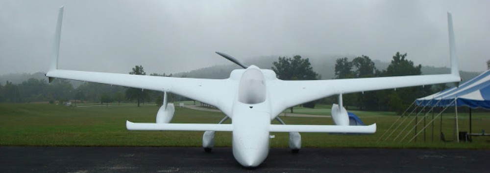
Thought I’d provide an interlude to the myriad of shop upgrade posts I’ve been making to have a discussion on the whole purpose of upgrading the shop in the first place: my Long-EZ build!

First off, Stacey was here visiting from Greensboro over the Thanksgiving holiday, and while she was here I definitely wanted to have her try out the Oregon Aero back seat cores. If I had been thinking I would have grabbed some selfies of both of us in the bird, me in front and her in the back seat, but alas I wasn’t.

Stacey –being a professional photographer– was thinking and she grabbed some pics of me messing about with the plane. Here I am at the start of our seat testing venture opening up the canopy . . .
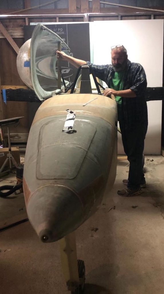
And then apparently thinking of all the shop tasks I have to do before I get back to building… only reason I can think of for looking so annoyed. Ha!
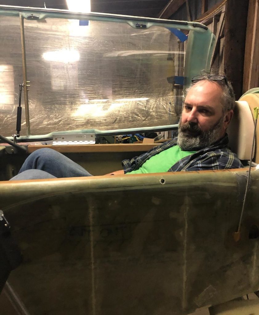
And below I was enjoying how nice the seat cores feel!

On a serious, note: I’m 5’11” . . . or maybe just a hair under that now. The law of unintended consequences reared its head as I was testing out the GIB seat cores. I realized that with the thigh support sumps built in, there’s only so far down you can go before you hit that hard stop.

You see, in the original Long-EZ you were sitting on a simple sloped seat… kind of like a banana shape. If you were taller you could merely scooch your behind lower/forward, bend your knees a bit more and get your head lower into the canopy. Again, with a “hard stop” literally keeping your butt from sliding lower into the airplane, it makes for a height restriction at just about my height (not planned btw). Sitting normally I have about an inch or two to spare above my head with the canopy closed.

So, at my height sitting on the thigh support has me in a more upright position than in a normal (stock) Long-EZ. This naturally puts my shoulders higher and thus more in between the longerons vs. underneath the longerons. You can still game the system in my back seat by scooching your behind further forward ON TOP of the thigh support, but this leaves an open air gap under your lower back. Ironically, I think I may need to have a small lumber pad to put in place for my taller pax!

Moving on . . .

A few days ago I was part of a 3-way FaceBook message going on between Mike Beasley, Marco and myself. I was working on the shop so was in total lurk mode as Mike and Marco discussed Mike’s placement of his autopilot pitch servo. At the start, Mike was considering putting it just forward of the stick at the base of the instrument panel. Marco adroitly pointed out that when he installed his AP pitch servo that it messed with his Whiskey Compass big time, and was the reason why he mounted the servo as reasonably far away from the panel as possible (just aft of the front seat).

Mike played around with Marco’s proposed pitch servo location and eventually made it fit… good for Mike and collaboration worked to save the day again.

However, this got me to thinking seriously about my Vertical Card Compass and it’s relatively close quarters with my AP pitch servo not even a foot’s distance away. Yep, my compass is stuffed in the upper right hand corner of the panel and the pitch servo is mounted forward of that on the right side wall.
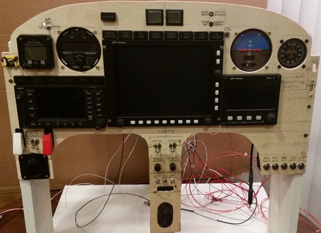
This potential issue got me researching and resulted in a phone call to Trio Avionics to confer with Jerry and Chuck on the matter. I learned that the Trio autopilot servos are primarily made of aluminum, with some plastic in the mix as well… which may be different than GRT or Dynon AP servos. Moreover, both Chuck and Jerry fly Long-EZs with both Trio autopilots AND vertical card compasses mounted in their respective panels, and neither of them have had issues with negative servo influences on their compasses.

They did however of course recommend that I install both compass and pitch servo and test out my configuration. That being said, I’m fully expecting to have to mount the compass in the upper left hand corner in a swap-out with my MGL clock/timer.

As I was assessing the probable position swap of my clock/timer and compass to opposite sides, I noted the minimal amount of space I had for anything in the upper right corner of the panel. It was then that I remembered that after making the decision to mount the Trig TT22 transponder in the right outboard strake, that I had moved the panel positions of both the TruTrak ADI and the Vertical Card Compass inboard about 1/4″. I grabbed an older (not the latest) cardboard panel to test if I was remembering correctly: Yep, I was.
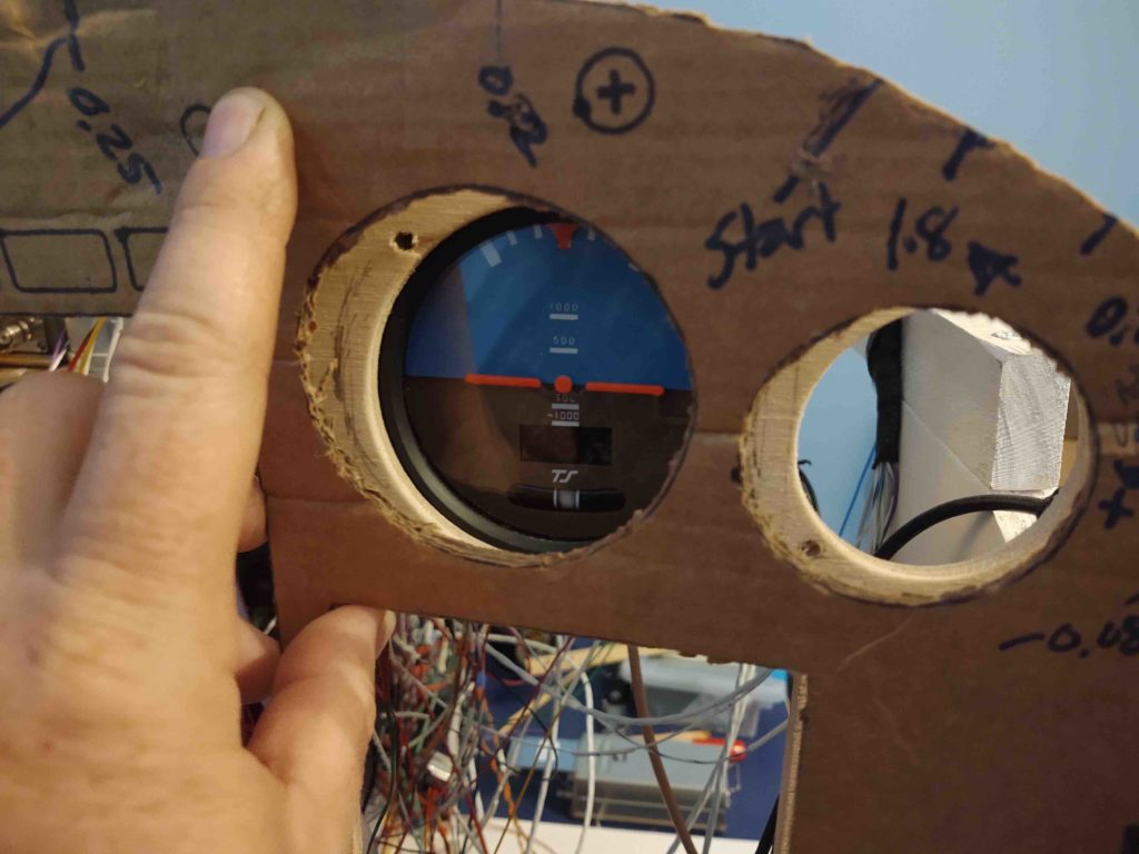
I then spent the next couple of days –when I had a moment to think– pondering my courses of action. First, I could easily just move the TruTrak ADI and the Vertical Card Compass back outboard to their original positions. But to be honest, I like the better symmetry of these instruments’ new positions and don’t want to change that.

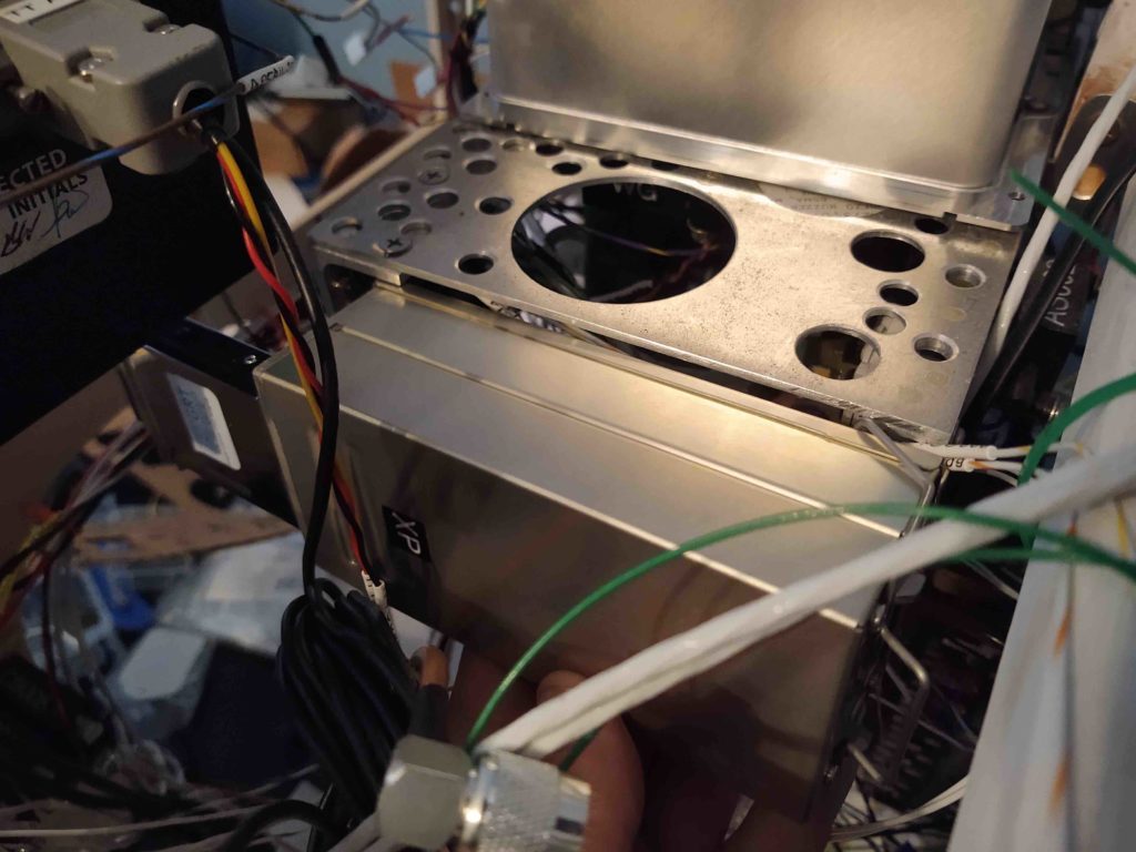
Then, upon further inspection it appeared that the real problem for fitting the Trig TT22 transponder was the GRT serial adapter. I then considered making up a 25-pin DSub to 25-pin DSub cable to allow the serial adapter to be placed somewhere other than on the front jack physically connected to the transponder unit. But that would require A LOT of work and a good bit of money for all those D-Sub connectors.

Thus, my final course of action and the solution I plan to go with will be to simply build and install a 90° bracket to allow the Trig TT22 transponder unit to be mounted on the right side of the TriParagon’s top shelf. I still have to check final clearances, but so far this is my plan. In addition, if I ever swap out my TruTrak ADI in the future, the screw pattern I’ll use for the bracket mount to the top shelf will be the same as the transponder bracket… allowing me to mount the transponder unit back in place on the top shelf whenever space allows.
Don’t go anywhere… there’s more!

Over the past few days I’ve also been locating and collecting up all my tools, gadgets and consumables to allow me to build the wiring harness for the Trig TY91 COM2 radio (minus the 4 wires to the intercom). This will allow me to fire up the TY91 and have it connected to the GRT HXr EFIS so I can configure the COM2 control functions.

In addition to instituting a major switchology reconfiguration and doing a bunch of wiring diagram updates, I’ve also been taking a hard look at my ground busses and scrubbing those to make room for all the connections. I mention this because below is the WxWorx box power connections (left) included with the Trig TY91 COM2 harness (right). You may note that the ground wires of each component are combined together in, again, an effort to optimize my ground buss connections.
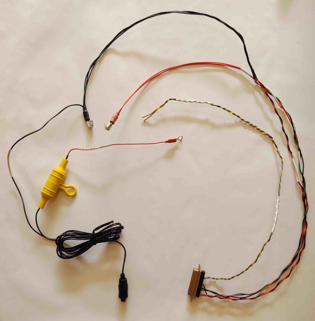
Over the next few days I will try to get my panel mockup repopulated and specifically the Trig TY91 COM2 radio connected and configured for control via the HXr EFIS. In addition, I do plan on firing up the WxWork system (although I don’t have a wx data subscription yet) to test out the Bluetooth connection with the Bendix/King AV8OR GPS unit.
Tooling Up – More Workshop Stuff

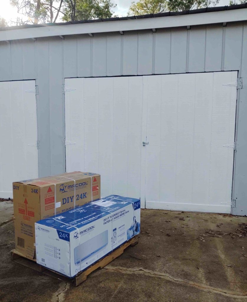
I ran around this morning to pick up more supplies and then returned home as I awaited the delivery of my mini-split HVAC system… which arrived mid-afternoon.

I then stowed it away in the work shop and ran out to get even more supplies, including more OSB sheeting for the next segment of wall that I intended on insulating and covering.

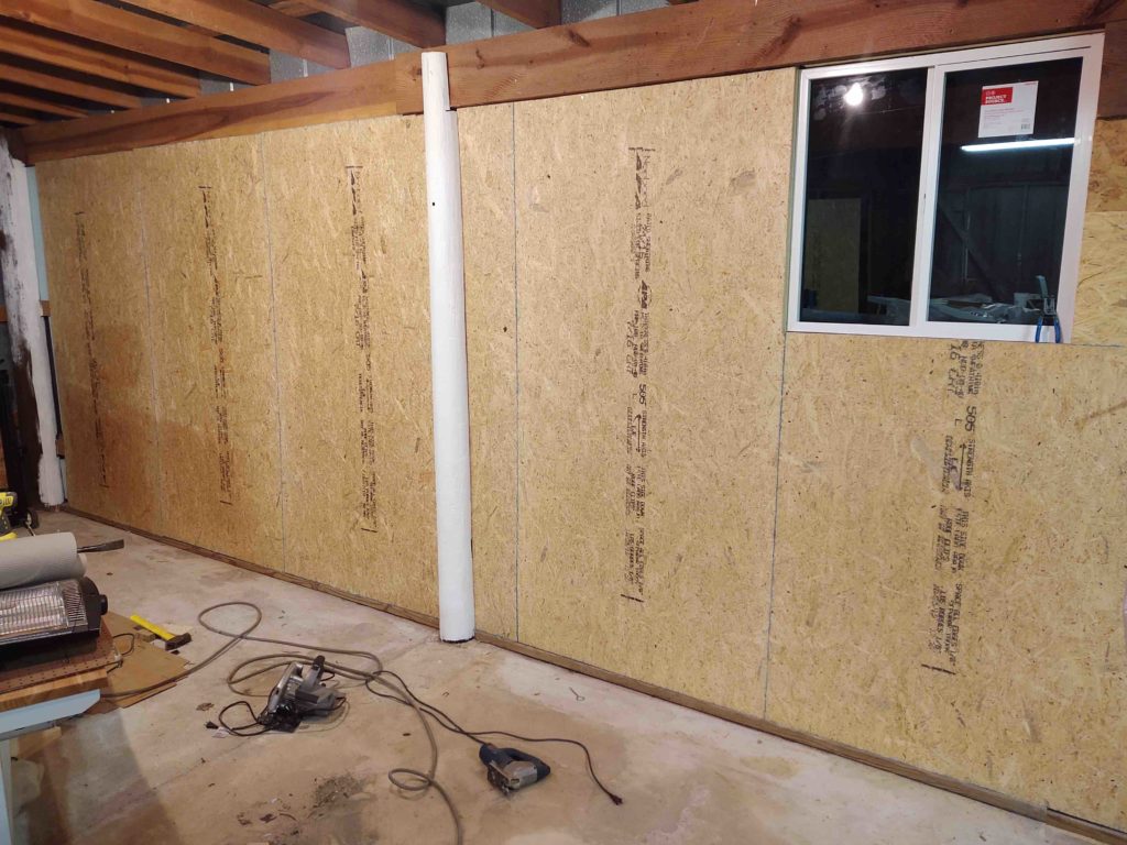
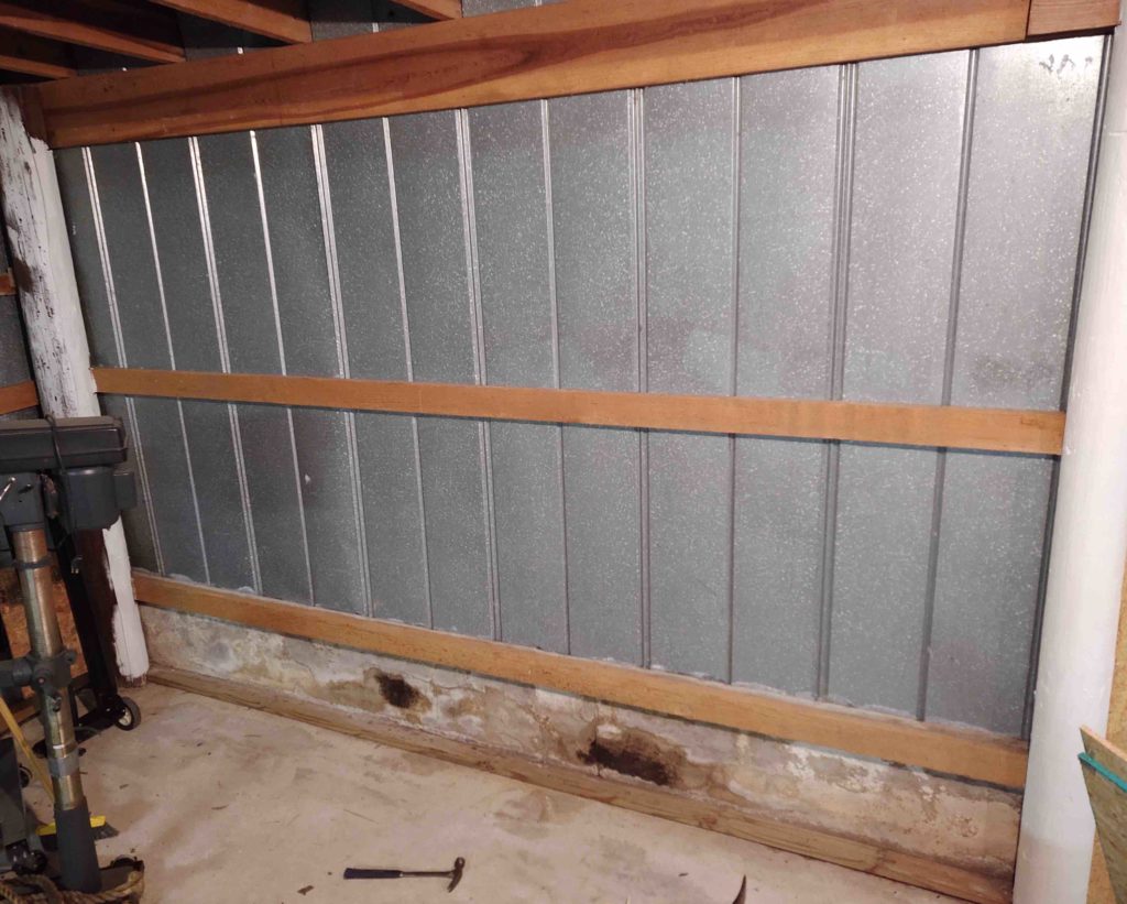
My first task was to remove all the nails and an entire row of wire hooks installed on the top board, with many of them having ropes hanging down off of them.

And yes, the stains look pretty nasty on the lower portion of the walls. I’m not sure what material they used, but it seems to be holding up well even though they all look terrible… and as a point of note it’s not mold.

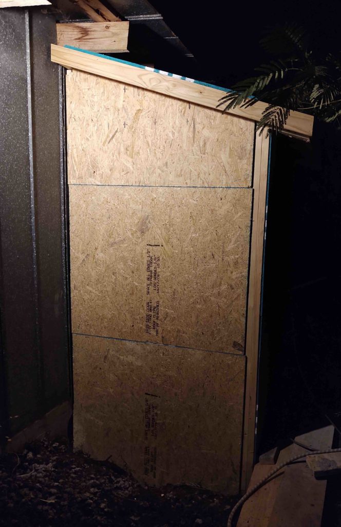
I then cut the 2″ thick foam pieces and inserted them in-between the wall purlins (boards). After the insulation was in place I simply installed three 4×8′ OSB panels in a row. I still have the very corner strip to finish, but this was a good stopping point for the evening . . . except…

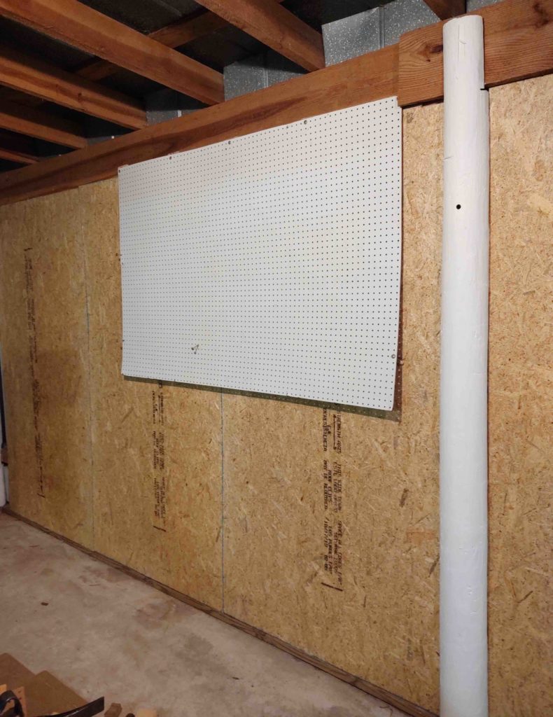
I then spent a good 30 minutes prepping and then mounting my peg board —which survived the tornado, but looked like a pretzel when I found it in the hangar— on the wall. Actually, I only ensured it was level and then mounted just the top screws. I’ll get the lower screws installed later.

If the weather is good tomorrow I’ll spend a good amount of time prepping and then start on replacing the workshop roof panels. Once the roof is done (as much as I can do over the next few days…to a week) I’ll get back to installing the mini-split HVAC system and then the air compressor.

Tooling Up – Shop Wall

Over the past few days I’ve been researching the final, no-kidding power requirements and wiring configurations for all the electrical stuff involved with the air compressor closet, the air compressor itself, and the mini-split HVAC system. After clearing up some bad assumptions and dialing in the circuit requirements, I got to work running the power wires to pre-install as much as I could.

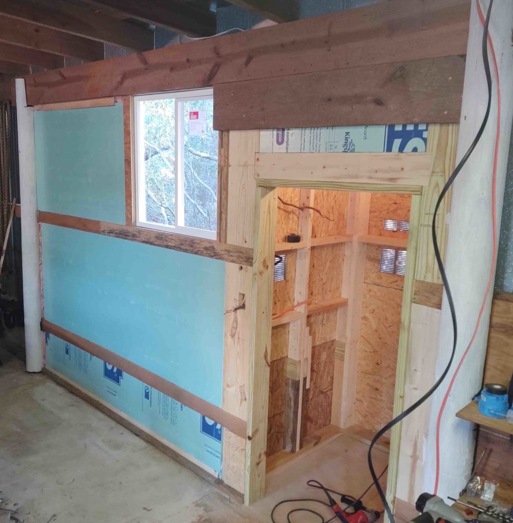
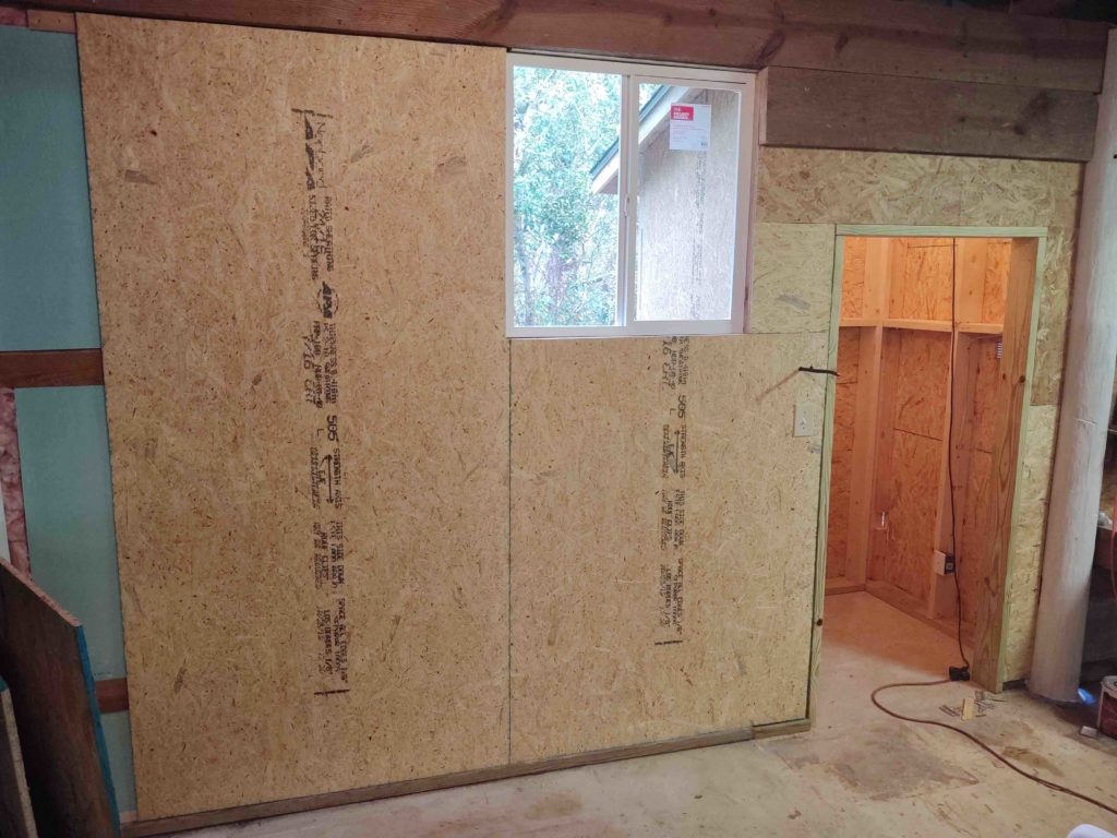
I then cut the 2″ thick foam insulation pieces to fit and installed them into the wall segment that I’m currently working: between the 2 big support poles (now white) that clearly includes the entrance to the air compressor closet.

Once I got the insulation foam piece in place above the compressor closet access door, I was then able to install the big support board that will be used to mount the inside mini-split HVAC system’s air handler unit.
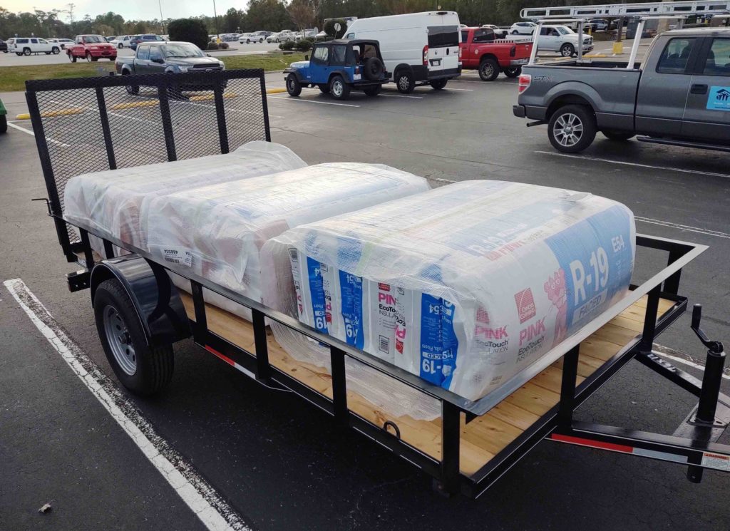
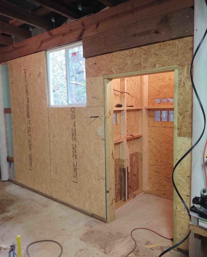
I then slowly (not by choice) measured and cut all the wall board pieces and secured them into place.

Yep, but in my rush I mis-cut one of the 4×8′ sheets of OSB and will have to recut the final left side strip after I pick up a few more sheets.

This is how the walls of the finished shop will generally look once I get all the insulation and wall boards cut and installed. The next section of wall to be finished will be to the left of this segment, that leads from the left-most white pole in the pic above to the left corner of the shop.

To the right of this segment will be a bit more entailed since I’ll need to replace another window and remove a rather hefty, robust work bench before insulating and sheeting that portion of the wall (which is the area where the machining mill will be placed).

As I’m working the process of insulating and installing the wall board, I’m also getting a better idea of the flow of the shop and will soon start installing/placing the glass cutting table, epoxy hot box, epoxy mixing station, etc.

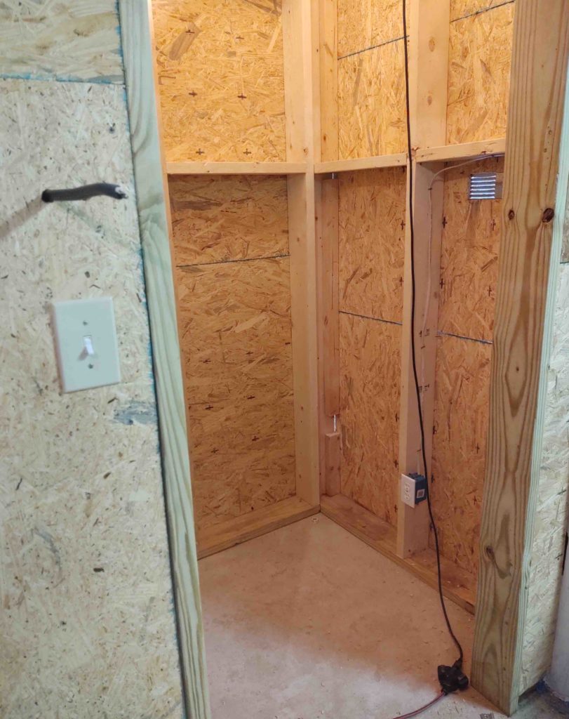
Below is a closer shot of the air compressor light switch on the left wall outside the closet and the electrical receptacle inside the closet on the right. The big black cable above the light switch is the air compressor power cable from the fuse panel that will get wired to a robust 60A switch that will allow me to turn off the compressor without having to get inside the closet to do so. There will be another 8 ga cable that leads from the switch to the compressor when it’s all installed.

My mini-split HVAC unit is due to be delivered on Monday. Since there is a lot of extra tubing between the inside and outside units that I’ll have to contend with [it comes with stock 25′ tubing that is pre-charged and thus cannot be cut to length without requiring an HVAC technician to come recharge the lines] I’ll be installing the HVAC unit before the air compressor to allow me unhindered access to the air compressor closet.

The struggle continues!

Tooling Up – Replacing Window

Yep, more shop stuff. Trust me, I’d rather be posting amazing and exciting details on my Long-EZ build, but gotta have a heated shop this winter and a cooled one this next summer for that to happen.

I’ve created the floor space for airplane building by removing the center pole and installing 4 huge beams, and I’m much closer to wrapping up the air compressor closet and associated HVAC unit install.

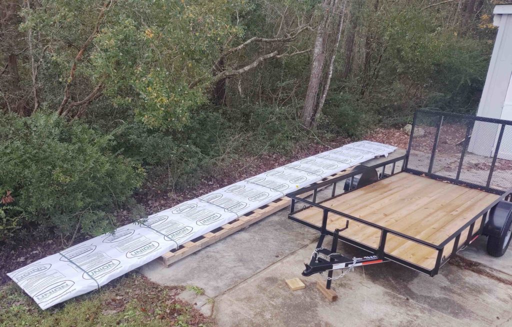
My 30 foot long roof panels were delivered today, but a box I ordered of critical self-tapping screws for the panel seams was not with the delivery… so tracking those down.

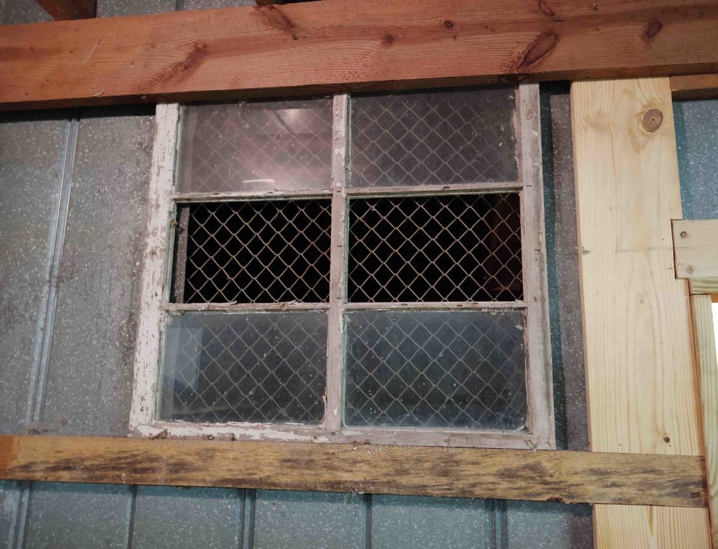
This is an old shop, built in the mid-1980s. The size is great and after looking for nearly 2 years for a house down in this area, it truly was the only property I found that had a “plug-n-play” shop that was big enough to finish the Long-EZ. At least, let’s say a house in my price range. But with the raw format of size and basic structure, there are certainly some issues I have to deal with.

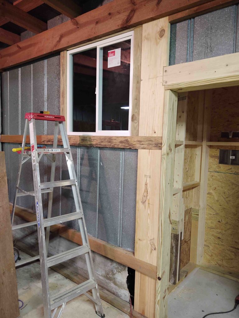
For instance, on the property plat my workshop is identified as a barn. Thus, I’m thankful it has 100A electrical service to it. But it does not have the aforementioned heat or AC, and there are literally some gaping holes on the structure. Two of those gaping holes are in the form of missing glass panes on the pair of windows on the back side of the workshop. The left one is shown here (just before I removed it).

After doing the mundane task of going back and filling in all the blank spots to secure the compressor closet exterior sheeting with screws, and another requisite trip to Lowe’s for more materials, I then got busy removing the chain link fence security apparatus and building out the window frame. I then installed a new window… a cheaper one, but still much nicer than what was there.

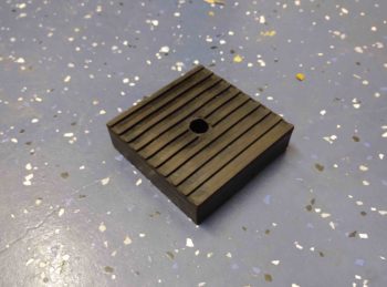
In an email conversation with my buddy Dave, we were discussing sound mitigation for air compressors. He mentioned rubber pads for the compressor feet, so I took this pic to show him what I’m using on my compressor.

Tomorrow will be a short day, but I’ll continue to do as much as possible over this holiday week.

Tooling Up – Compressor Room Roof

I got a call that my workshop roof panels are in, so I should be getting those delivered within the next day or two….

I then started off today taking a good hour to trace out the remaining electrical circuits in my shop. I had already done maybe over half of them, and finished the job this morning. I found some areas that I can improve efficiencies and save some space in the quite packed electrical panel by combining some lighting circuits.

I was then preparing to shingle the air compressor closet/bumpout roof when my airplane seat cores arrived. Well, that caused quite a kerfuffle… haha! And after all the excitement was over (it really isn’t… very happy with the seats!) I got back to work on the roof.

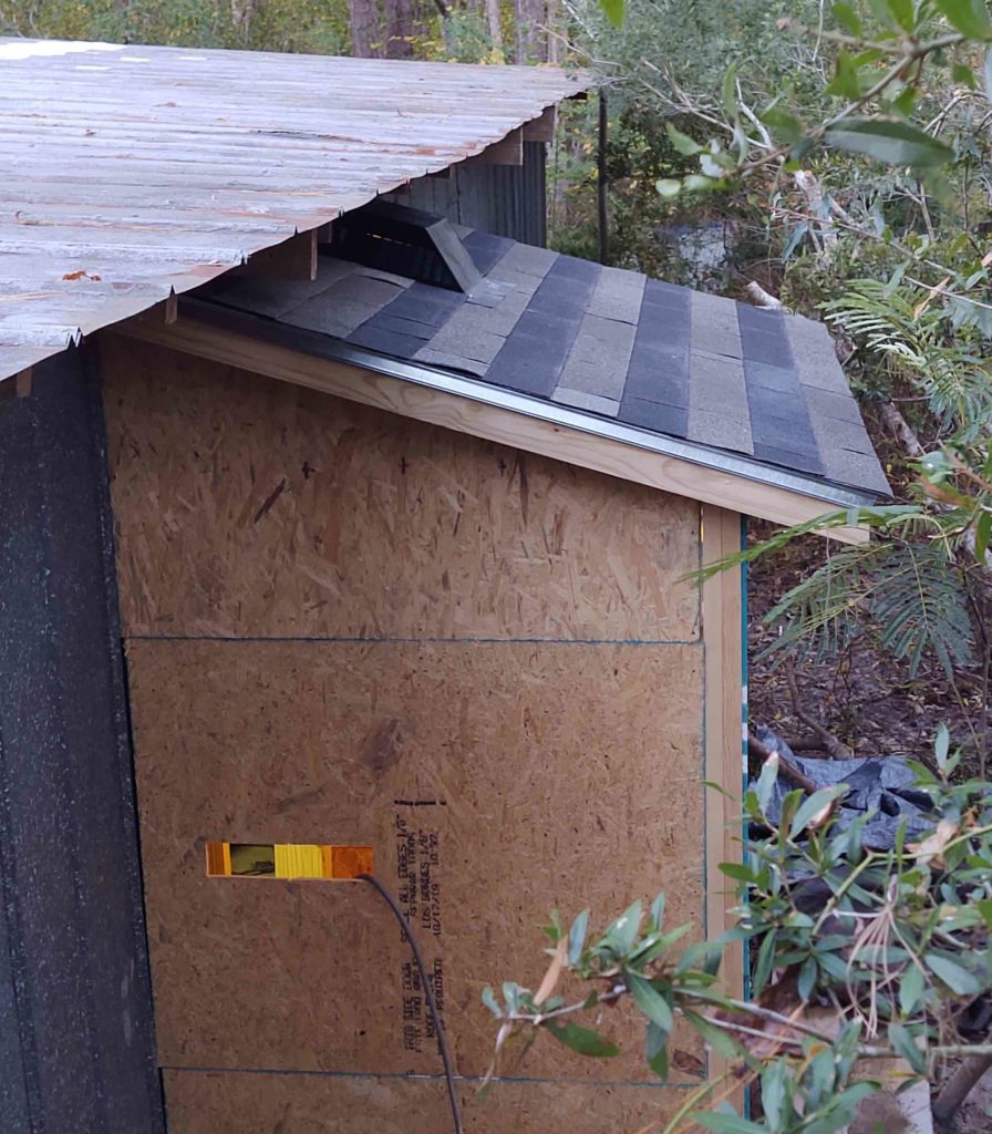
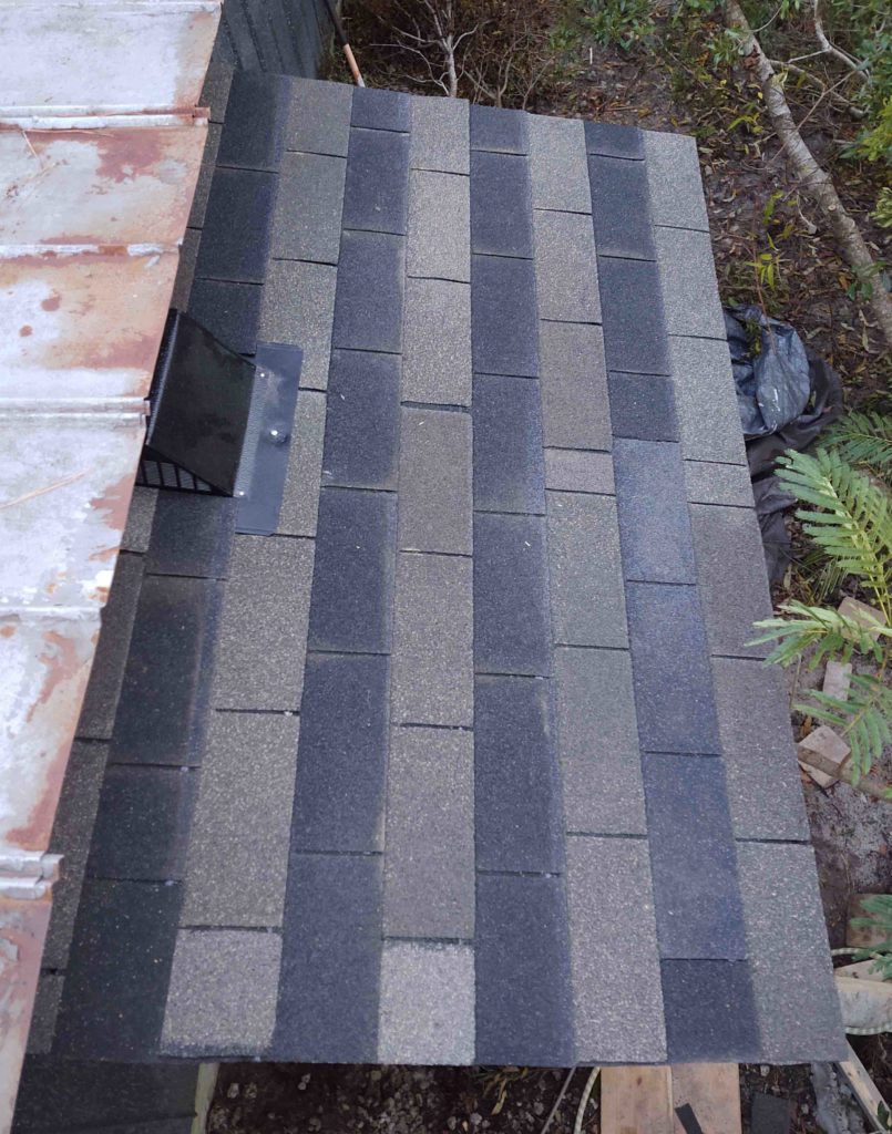
I used shingles simply because I had them on hand. The black shingles are from when I built my small shed for my previous house, and the lighter shingles were for a color match I had to do for a roof repair on the first house I sold in northern Virginia back in 2016 (not this last house I just sold). I didn’t have enough black shingles, so I merely combined the two colors… not a bad look I think. Although, who will see this??

Another shot of the shingled air compressor closet roof. Not perfect, but I think this dawg will hunt!

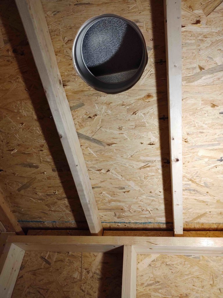
Note the vent on the top of the roof that I intentionally installed backwards –to help keep rain out of the air compressor closet– under the main roof overhang …

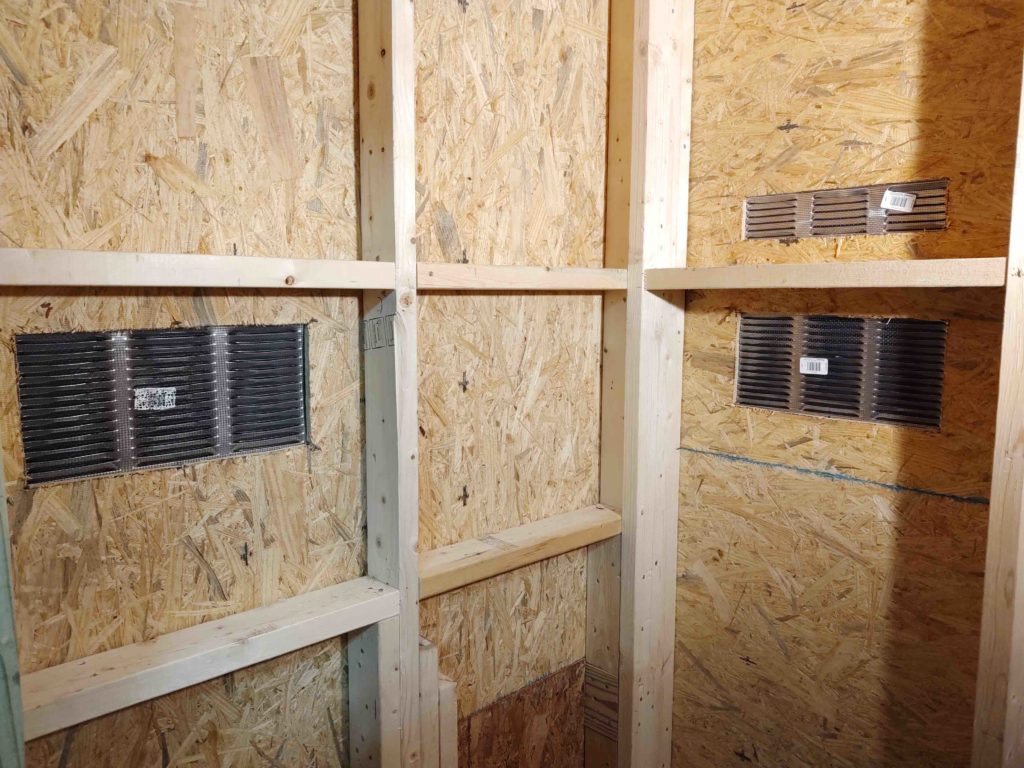
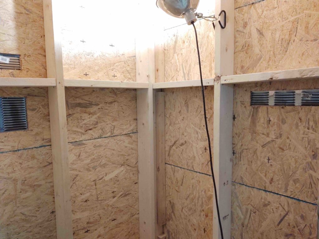
Here’s what it looks like from inside and is simply for providing fresh air to the compressor to help keep that beast cool.

I also added some wall vents… one on each side and two directly behind the air compressor’s cooling fan.

I also prepped the workshop window nearest the compressor closet to be replaced since the old one was, well . . . old and also had some broken panes. Since I’ll be adding foam insulation sheets around the shop side of the air compressor closet, I’m working the entire wall to be finished in and around the closet door. In addition, I’ll be mounting the inside HVAC blower unit above the air compressor closet door.

After tomorrow my workshop efforts will slow to a crawl for a few days during the Thanksgiving holiday festivities. But I will pick back up post haste following some Turkey, wine and football!

Chapter 22/26 – Seats & Cable

Or rather new seat CORES and new Trig TT22 Transponder ANTENNA cable….

As I’ve stated before, I may not currently be physically building my airplane, but I’m certainly in the game mentally and I’m really good at BUYING STUFF! ha

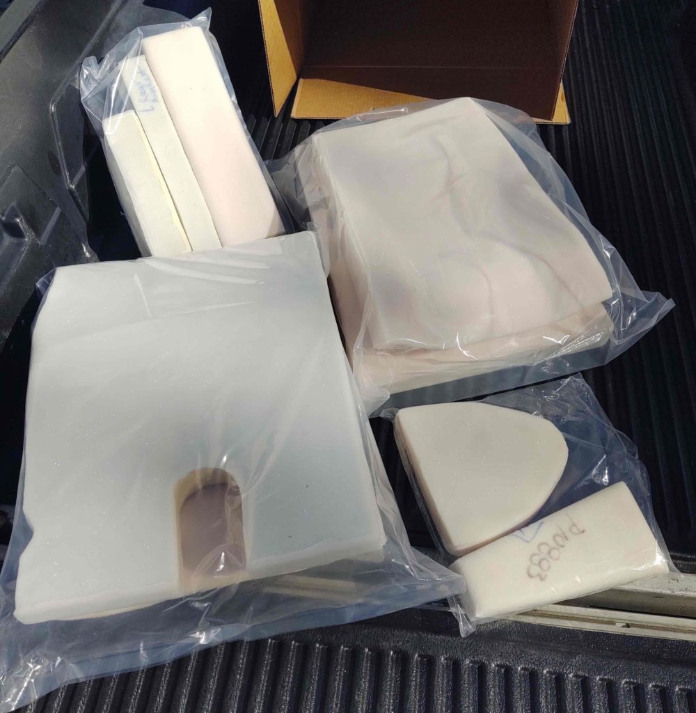
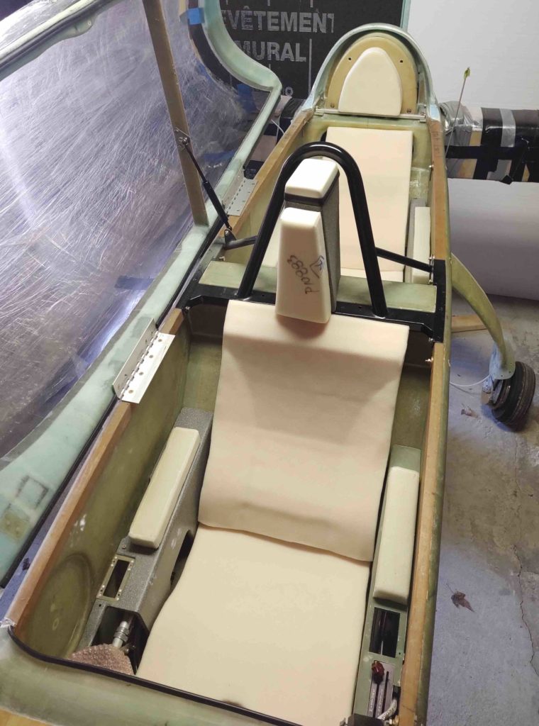
Well, today is certainly a milestone day. By taking a few measurements and shamelessly writing a check, I’ve wiped out half of Chapter 26 – Upholstery. And certainly the bigger half: the cushion fit, as my Oregon Aero seat cores arrived today!

Actually, not just the seat cores, but the headrest and the armrest cushions as well… the whole kit.

I was in the middle of working on the air compressor closet when the seat cores arrived, and this was just too exciting not to take a break and see how these babies fit!

I found 3-4 minor tweaks that need to be made (which is the point of this test fit phase) but I am overwhelmingly tickled pink with these seat cushions and accessories.

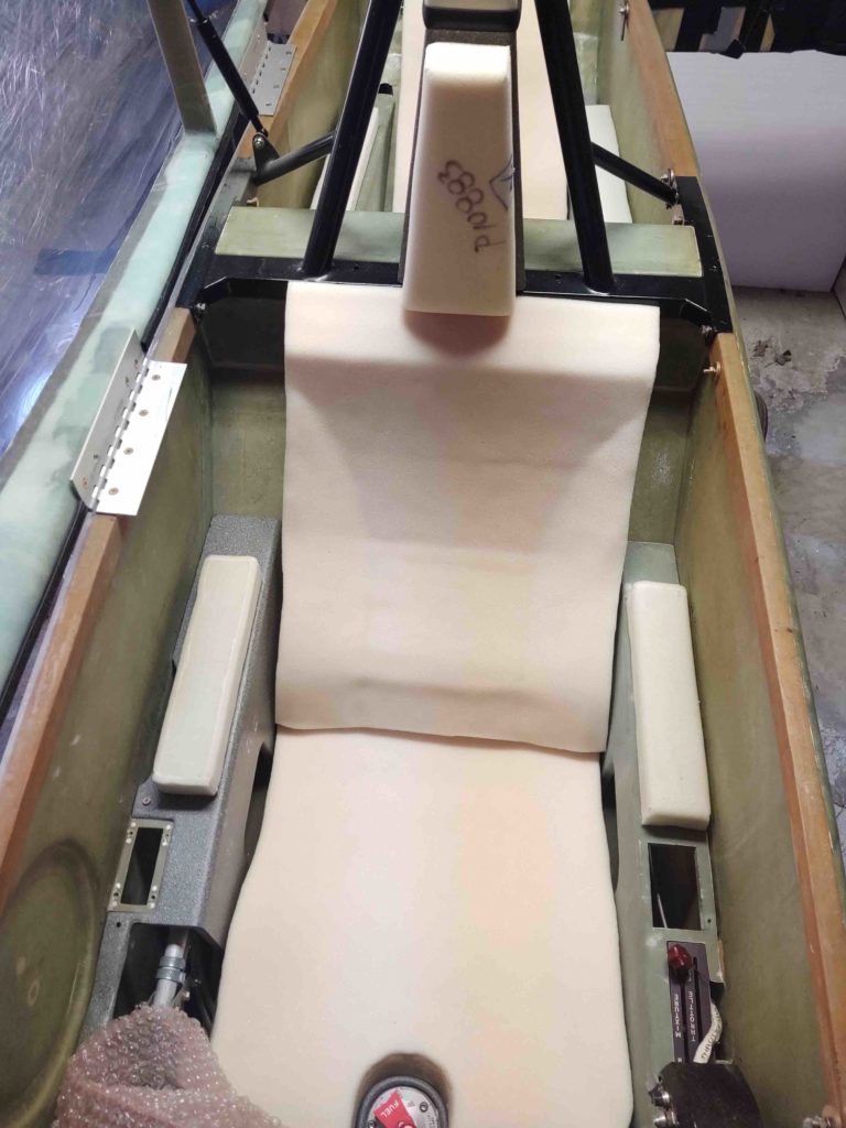
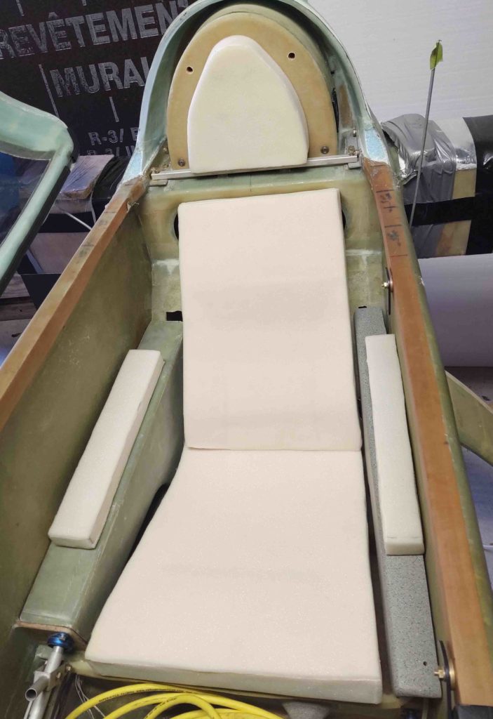
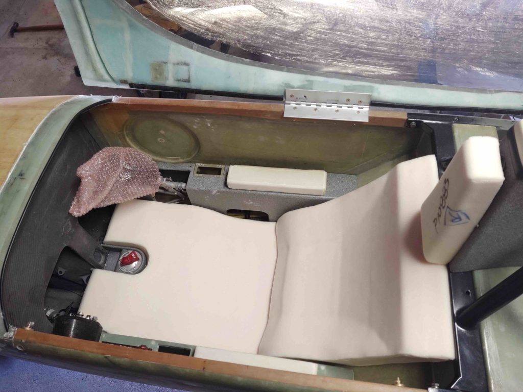
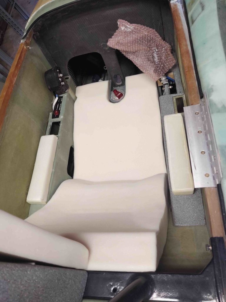
Here’s the front pilot seat . . .

I would like Oregon Aero to make the cut out around the fuel valve a little more vertical so that it hugs the aft curved wall of the fuel valve a little closer. Again, nothing major… at least anything that if it didn’t get tweaked it would affect seat cushion fit or comfort in any way. Just a stylistic preference.

And the GIB seat.

I gave Oregon Aero measurements at different heights for the GIB headrest, so it came out a bit more “angled” than I prefer, so I’ll have them round it out it into a smoother curve all the way around.

Below is the front seat again.

The big tweak that is significant in my book —that I’ve had a lot of feedback on from current EZ pilots— and a requirement that they missed my instructions on, is to taper the front of the thigh supports on the leading edges of the lower seat pad. If these pads are thick near the bottom of the panel leg holes, then it really messes with your ability to extricate yourself from the airplane gracefully as the heel of your shoe will catch that thick seat pad.

An over-the-shoulder view of the front seat pads. Again, I’m super happy with these seat cores… and honestly, it feels great to see the build moving forward again.

The next step on the seats is take a good 30-60 minutes to simply sit in the seat while making airplane noises, check the view out the canopy of course, and triple check the feel of the seat cushions. Then I’ll send the cores back with my list of demands <grin>, my color choices for the upholstery covering, and (let’s not forget!) my electric seat warmer pads. They will finish all that up back at Oregon Aero and once done, I’ll virtually be finished with Chapter 26 [a little velcro will need to be added about the cabin of course].

Moving on…

One takeaway from last week’s test fitting of the Trig TY91 com radio and the Trig TT22 transponder on the TriParagon’s top avionics shelf (which they both barely fit) was that with the transponder getting installed back into its original spot behind the panel AND the transponder antenna getting mounted in the forward NG30 pocket, I was ready to pull the trigger on the cable.

Normally for com or nav antennas I would simply make the cable, and I do hold that option in reserve. But Mode-S transponders are reportedly known to produce a good bit of noise if steps are not taken to mitigate it (especially in older ANR headsets). The biggest way of reducing this noise as much as possible is by using RG-400 cable for the antenna. So, instead of me making the antenna cable, I left it to the experts and ordered it from the WiFi Experts out of California.

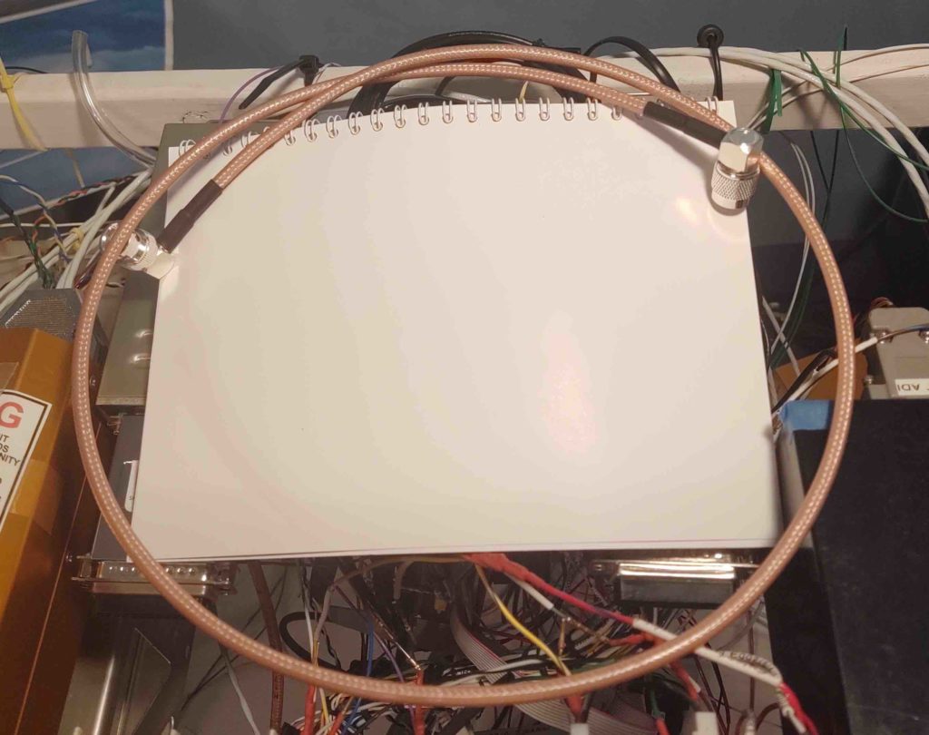
Here’s the Trig TT22 transponder-to-L2 transponder antenna cable, with a 90° TNC connector on the transponder side and a 90° BNC connector on the antenna side.

Again, slowly inching forward to eventually get this bird in the air.

Tooling Up – Compressor’s long trek

Today I started out by initiating the long-haul move of the air compressor from the garage back to the workshop.

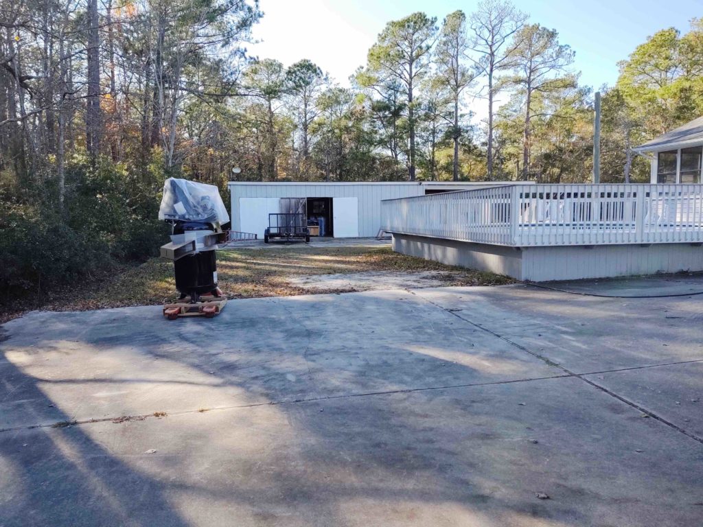
Here we have the beginning of the air compressor’s long trek to the workshop.

I had considered leap-frogging pieces of wood sheeting to make it over the grassy area, but then I further assessed the pea-graveled grass area and decided I would chance not using the wood sheeting… and with a “running” start it worked out fine as I just kept it rolling non-stop from the front to the aft pad of concrete.

I then spent a good hour measuring, cutting and installing the wide 2×10 and 2×6 lumber around the installed doorframe to add reinforcement and buttress up the surrounding wall.

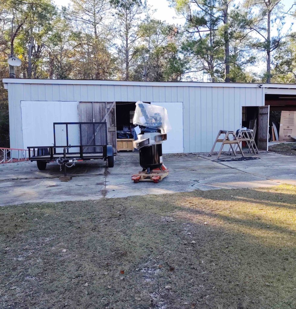
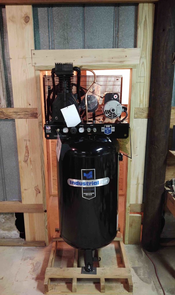
I then unveiled the air compressor and set it in front of the air compressor closet door opening to provide a preview of how it will fit [I can’t fit the compressor into its closet while it’s on the pallet since it’s too tall. But once it’s removed it will fit just fine].

Tooling up – Compressor room door

I didn’t really get a lot done on the air compressor closet today, but I did get a bit knocked out.

I started off with a trip to Lowe’s to pick up another round of much-needed items. I then grabbed a load of stuff out of my storage unit in search of my hammer drill… which will allow me to easily drill the holes in the concrete to hard mount the compressor. I think I’m close to the box that has my hammer drill, so within the next day or so I should have it in hand.

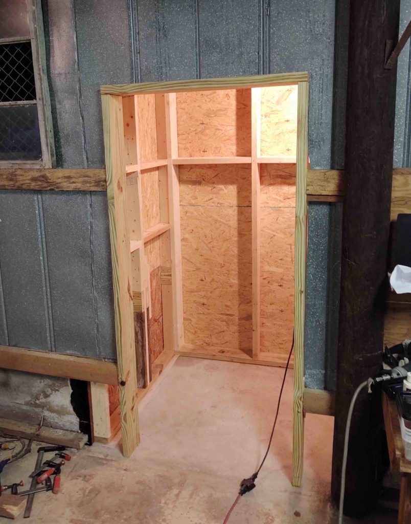
Later in the evening I finally finished cutting out the metal doorway that leads into the new air compressor closet. I then cut the 2×6 doorframe that leads into the air compressor closet, after which I nailed the doorframe together and installed it into place.

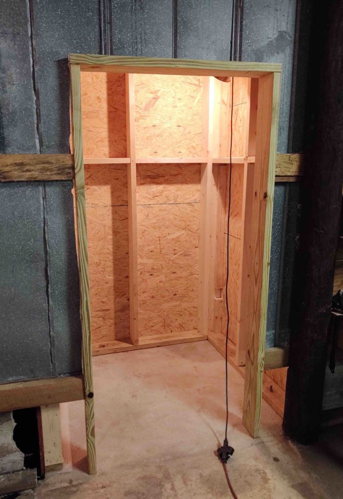
Here we have simply another angle showing the framed and installed air compressor closet doorframe.

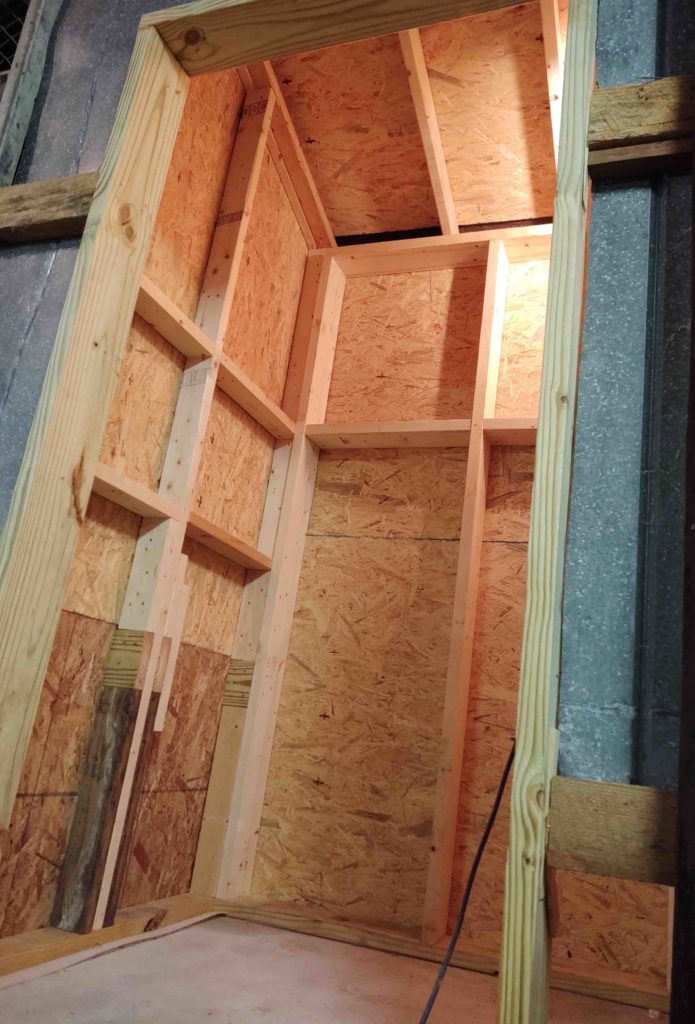
And a shot showing the interior air compressor closet framing.

Tomorrow I plan on getting a whole lot more knocked out on the air compressor closet…

Tooling Up – Compressor closet walls

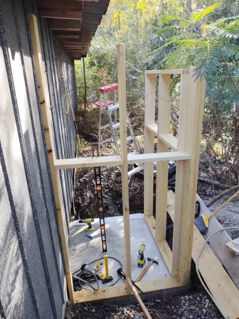
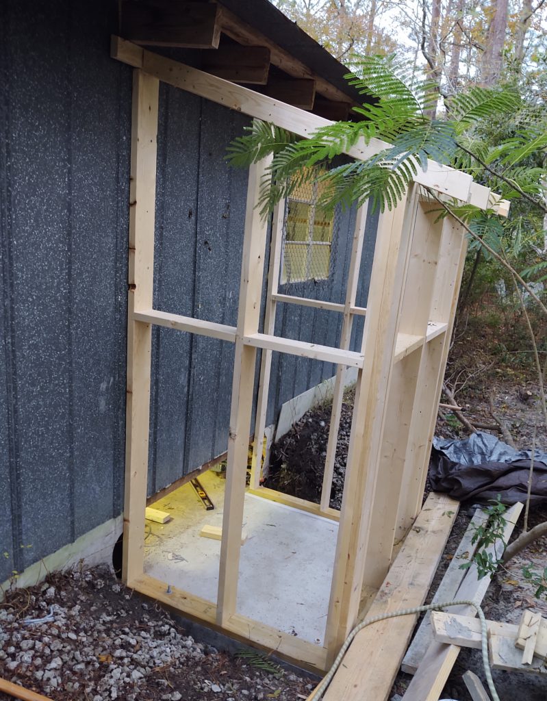
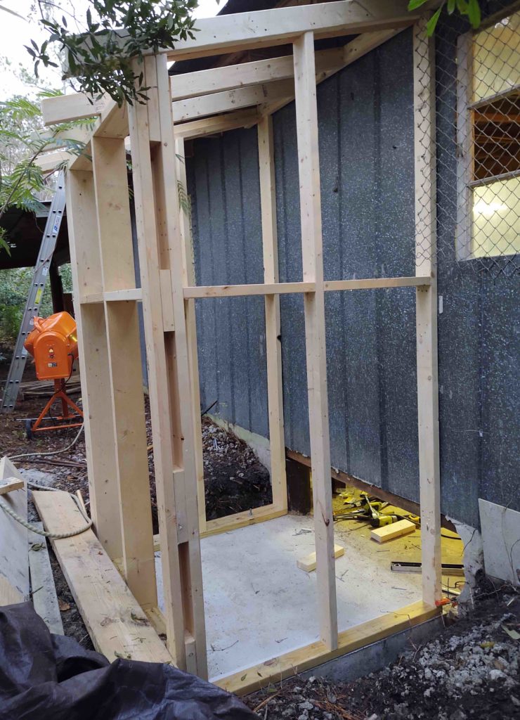
Yesterday I framed out the walls on the air compressor closet and was also able to get the roof joists in place.

This pic was taken mid-day . . .

And these below right before it got dark… which happens so quickly now.

Here you can see I have the roof joists in place. The entire structure is just a tad bit taller than I’d like, an inch and a half to be exact, since in my mad rush to both design and build –pretty much concurrently– I forgot to account for my 1-1/2″ thick bottom stud plate in my measurements. This of course drove the roof joists right up under the existing joists.

Here’s a shot of the left side. If you’re wondering about the chain link fence over the windows, I guess the previous owners thought that this was a sort of poor man’s security bars or something.

DAY 2: As a side note, my Porter Cable framing nailer stopped working after 15 years of faithful service, so I ordered a refurb kit for it… which I did some poking around on the Internet today to find the best deal.

I then took advantage of the Black Friday sales (and some other discounts I scored!) to order my Mini-split HVAC system from Lowe’s and also grab all the insulation I’ll need for both the shop ceiling and the air compressor closet. I have to say that buying in bulk here got me contractors’ pricing and I saved a ton.

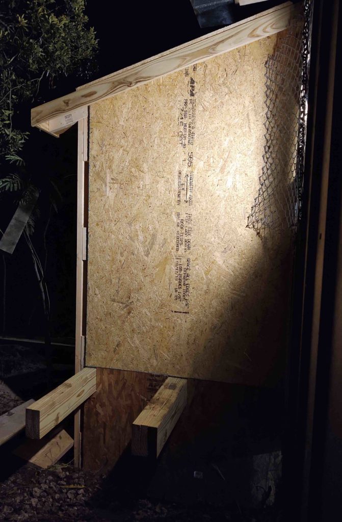
I then went home and finished cutting and attaching all the sheeting (save 11″ on the lower edge of the roof) to the framed air compressor bump out.

Here we have the right side of the air compressor closet.

And here’s the left side.

Note I took a bit of time to build some cantilevered 2×6 arms extending from the air compressor closet’s left wall that will be used to mount the mini-split air conditioning system’s external condenser unit.
Rain is forecasted for tomorrow, but I’ll continue to work as much as I can on the interior of the air compressor closet.
Tooling Up – Compressor Closet

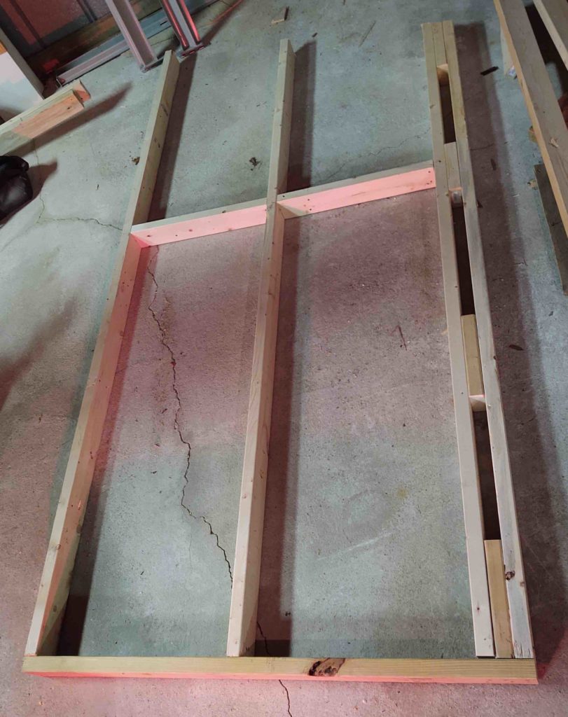
Yesterday I started cutting the studs and bottom plates for the air compressor closet walls. I’m framing the right and back walls with 2×6 studs and the left wall with 2x4s. I have some plans to extend out from the left wall next year, so I’m fine with using 2×4’s now.
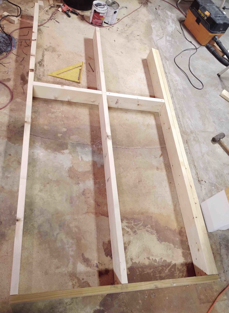
Today I finished cutting all the wood and here is the right wall framed, the outside facing up.

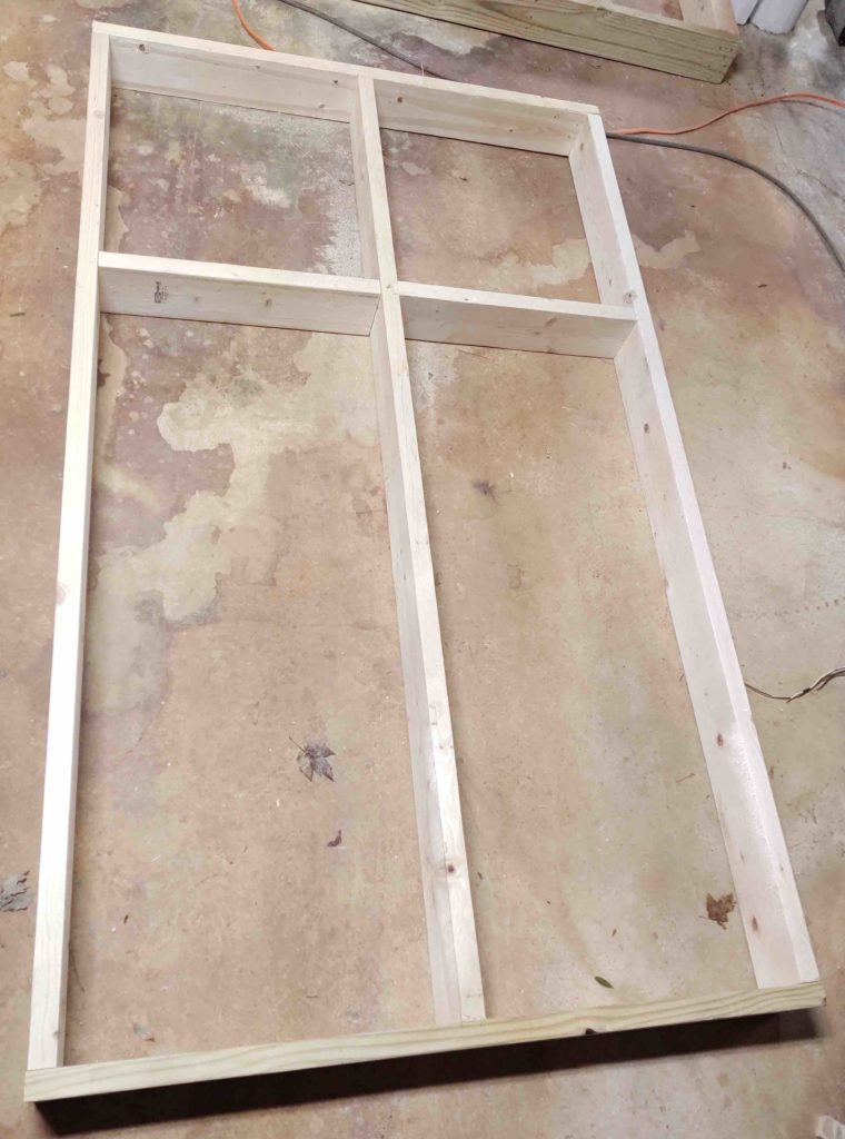
I then framed out the 2×4 left wall. This is a shot of what will be the interior side.

Then came the 2×6 back wall. It’s symmetrical so it doesn’t really matter which way it goes in.

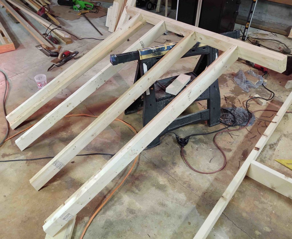
And here we have what I framed up yesterday: the roof joists with the ledger board that will attach to the outside of the current workshop. It’s not complete yet as the 1×4 sides and fascia will be added after this goes up.

I have a couple of days of good weather before it gets rainy again, so I’m trying to get this thing framed and as closed to finished as possible over the next few days.

Tomorrow the walls and roof will go up and then I’ll start working the actual fitting & placement of the compressor before all the wall sheeting is installed.