Chapter 18 – Headrest fever!

My plan was to work about half a day on the headrest and then get it glassed into the fuselage and move on . . . that did not happen.

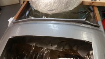
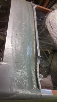
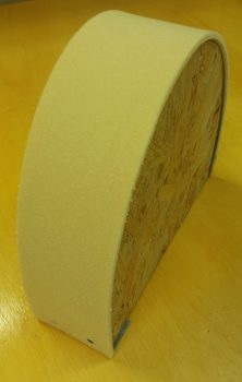
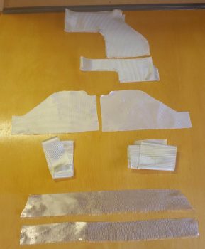
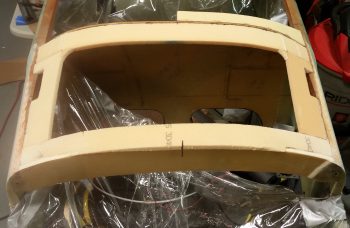
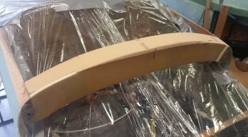
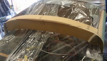
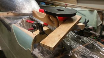
I started off by cutting out the front face cover of the headrest out of 3/8″ thick PVC foam and then carefully sanding it so that the cover’s edge was just slightly smaller than the headrest’s, to allow for the thickness of the glass.

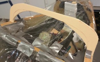
I then rounded the edges of the headrest front face cover piece.

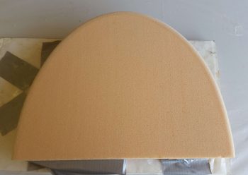
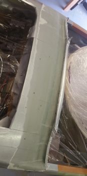
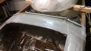
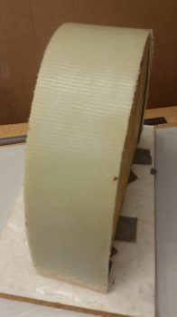
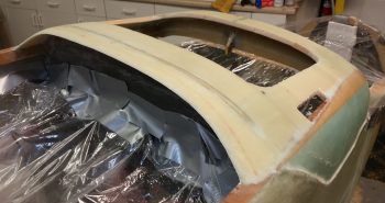
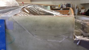
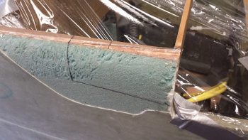
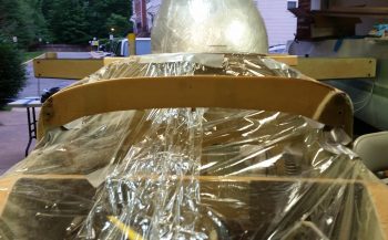
I then glassed the front headrest cover piece with 1 ply of UNI with the fibers running horizontally and then 1 ply of BID on top of that.  I will say I finagled with the edge for a time to get the glass to lay down as nice as possible around the edge.  I peel plied the cover layup and let it cure.  I will also note that because of my aforementioned aligning issue with the right engine mount extrusion, I had to add a small strip of foam on the bottom edge of the right side.

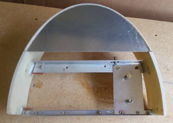
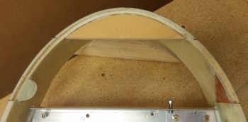
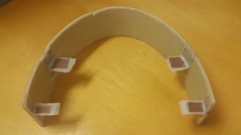
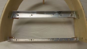
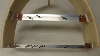
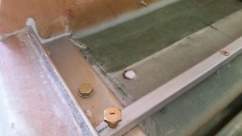
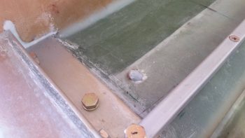
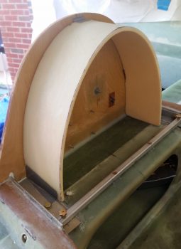
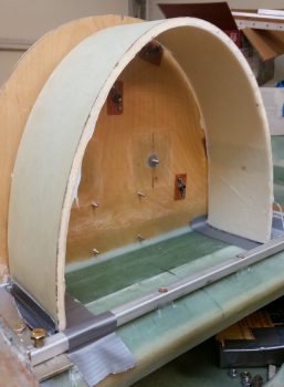
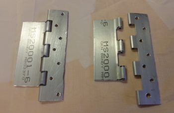
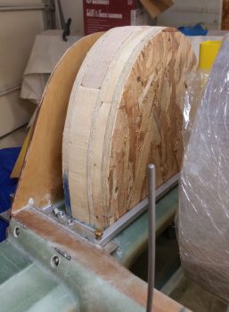
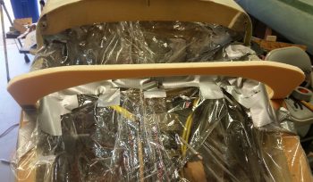
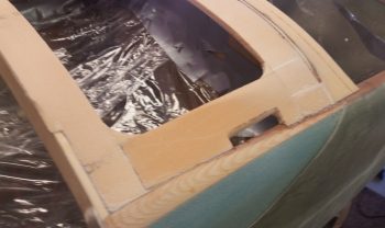
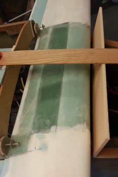
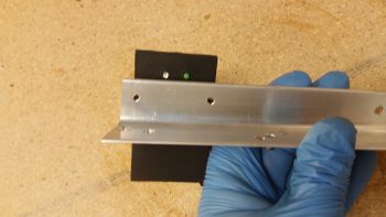
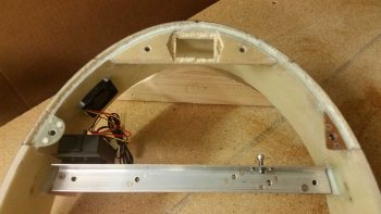
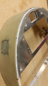
Barely visible in the pic below is an added set of #8 nutplates on the upper angled aluminum crossbar mount tabs sticking out from the sidewalls.  I’ll point this later on, but these are for a pair of #8 CS screws –one each side– that actually hold the crossbar in place, since the bigger #10 screws that previously held on the crossbar did double duty and also held the SD-8 heat sink mount and Electroair controller in place, respectively.  If I removed either of the #10 screws to remove either component, I was unhinging either side’s mounting point of the crossbar.  These #8 CS screws allow the mounting crossbar to be held in place regardless if components are installed or not.

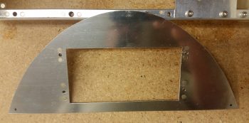
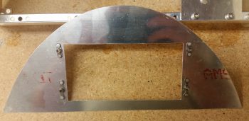
I then got to work on the headrest top plate.  I drilled, counter sunk and riveted in the nutplate assemblies for the lower top plate mounting screws.  I had to go one size up than I had planned, to #10 screws, since I am rapidly depleting my nutplate bench stock!

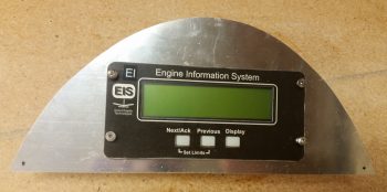
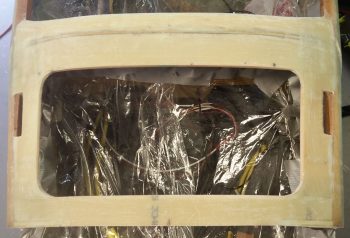
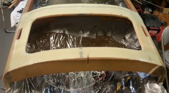
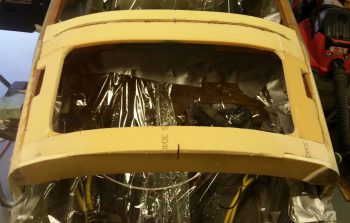
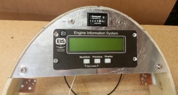
Also, I measured, marked and cut out a rectangular window above the EIS4000 cutout for the Hobbs meter to peak through.

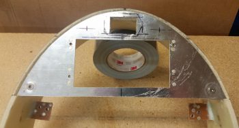
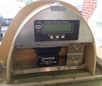
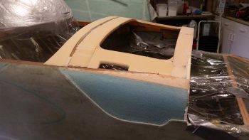
Here’s a quick mockup with the Hobbs meter now visible and the EIS4000 set in place. Note that the EIS4000 screw holes have been countersunk so that the screws will sit as flush as possible.  Also note that I drilled and countersunk the top #10 screws for the top plate, although the nutplate assemblies have not been floxed into place yet.

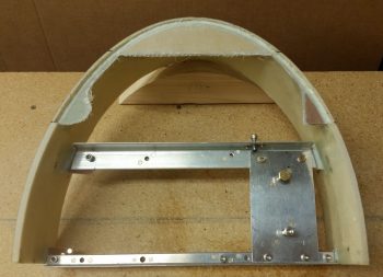
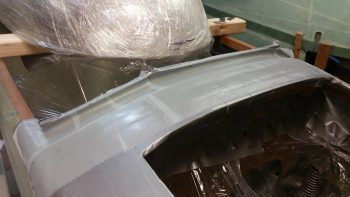
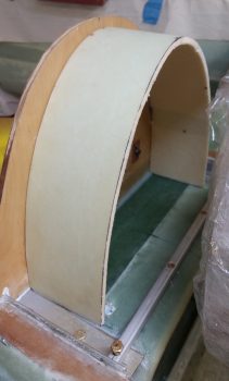
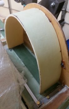
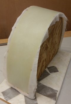
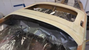
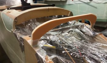
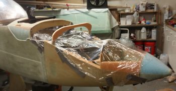
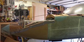
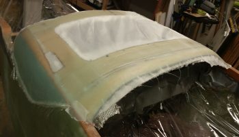
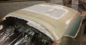
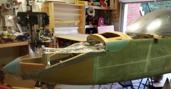
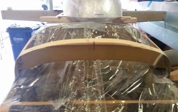
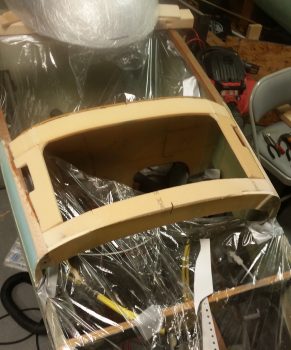
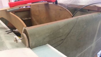
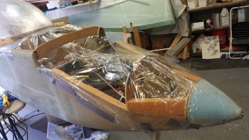
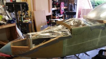
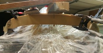
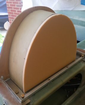
I then set the mocked up top plate & headrest into place on the fuselage.  I have to say I’m very pleased with how the headrest is coming along, although it is taking a bit of time to complete.

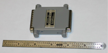
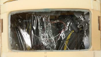
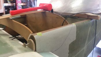
When the GIB headrest is glassed into place on the fuselage, I want it to be as complete as possible with all components, no matter how minor, small or “important” to be accounted for and set in position.  Thus, I had been mulling over where exactly to place the very lightweight cooling fan thermal control unit in this matrix inside the headrest.

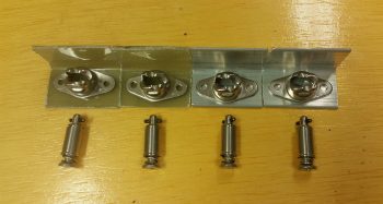
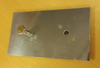
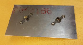
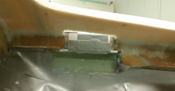
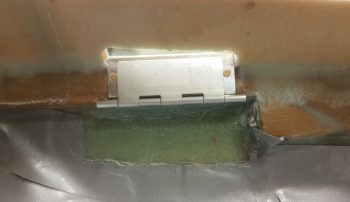
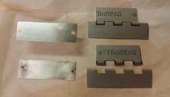
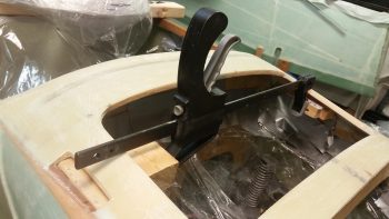
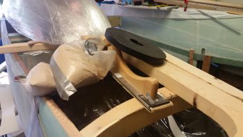
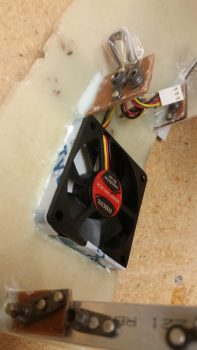
I decided that it would go on the right side, mounted to the upper mounting crossbar, adjacent to the interior right headrest sidewall.  I decided to use velcro to secure it in place, but wanted something a little bit more secure as well.  So I drilled 2 small holes in the top of the angled aluminum mounting crossbar and then notched the flange on the cooling fan control unit to match the holes.  This way I can use a piece of cable lace to positively secure the cooling fan control unit in place in addition to the velcro.

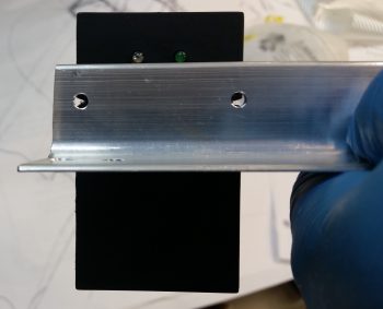
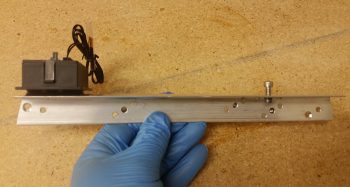
Here’s another shot of the cooling fan control unit held in place with velcro with the 2 wire lace holes visible.  Note that the operating LED indicators are located on the forward side of the mounting crossbar, so that they will be visible with the headrest front cover removed.

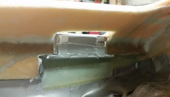
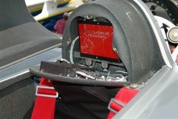
This shot shows how it will look when mounted inside the headrest.

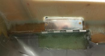
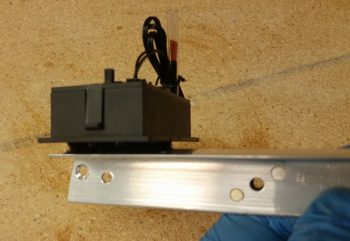
And just a final closeup of the cooling fan control unit mounted in place with velcro.

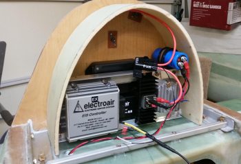
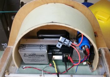
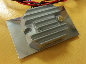
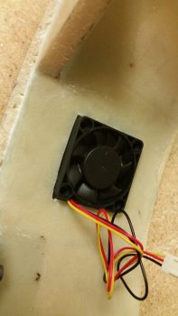
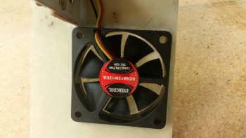
With the cooling fan control unit mounting squared away, it was time to turn my sights on the fans themselves.  I have one 60mm cooling fan that blows external air into the headrest, and is positioned –not coincidentally– right next to the SD-8 voltage regulator.  It also is positioned so that it blows cooler air right down the row of bottom mounted components in the headrest: SD-8 voltage regulator, SD-8 bridge rectifier (mounted on a heat sink) and the Electroair EI controller, all which have cooling fins to facilitate cooling during normal operations.

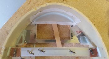
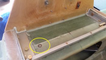
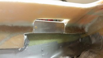
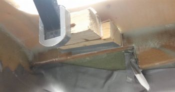
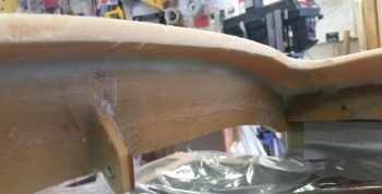
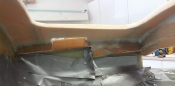
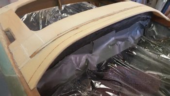
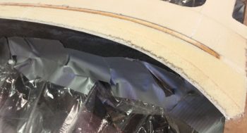
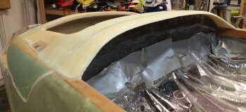
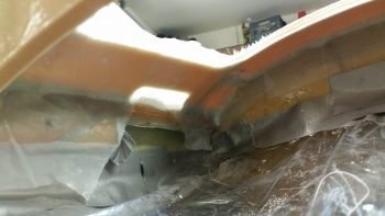
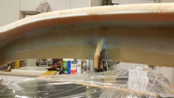
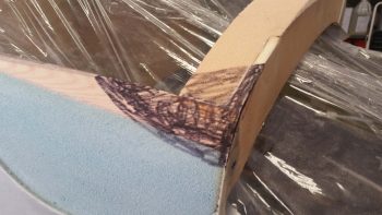
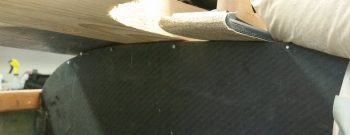
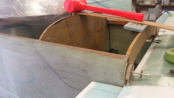
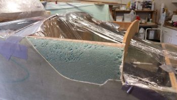
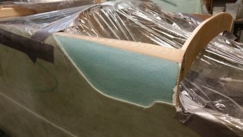
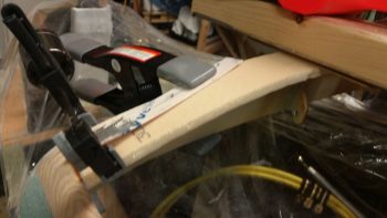
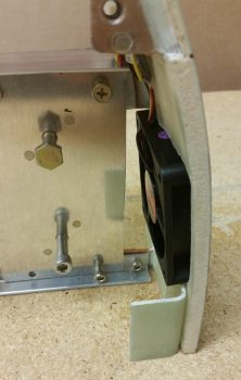
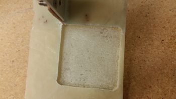
I then have a 40mm exhaust fan to remove all the warmer air from the headrest housing. It’s positioned on the high side (warm air rises) at about the 10 O’clock position when looking straight at the front of the headrest.  Since I did not want to have the air flowing through thick cutouts into the headrest sidewall, I decided to simply place the exhaust fan as flush as possible with the external glass of the headrest.  To do this I clearly had to remove the internal sidewall glass and the foam in between, as I did below.

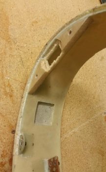
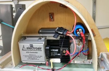
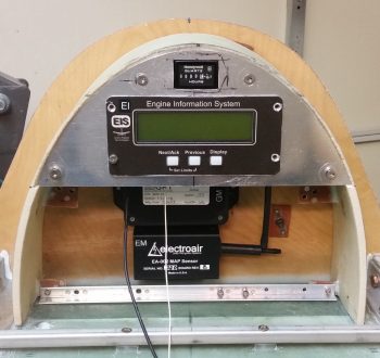
This allowed the exhaust fan to sit right against the external headrest glass, and reduced the footprint of the exhaust fan considerably by embedding it in the sidewall.

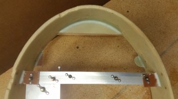
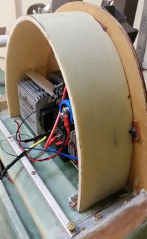
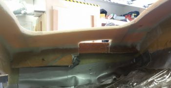
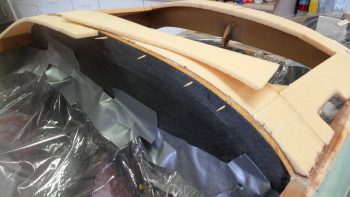
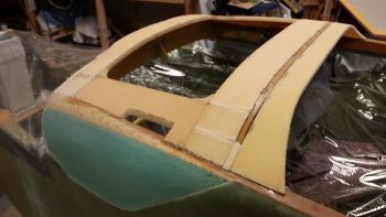
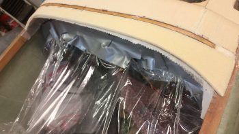
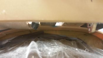
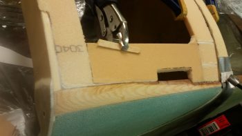
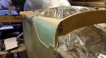
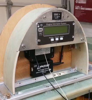
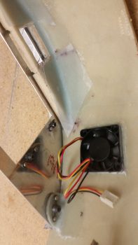
This pic actually shows quite a bit.  You can see the cooling fan controller unit mounted in place with velcro atop the mounting crossbar.  It also shows the position of the embedded exhaust fan.  If you look at the glassed in foam reinforcement piece at the top of the headrest arch, you’ll see the foam and glass dug out to allow for the Hobbs meter to be set down below the surface of the top plate, slightly embedded as well. Finally, if you look closely you can see the #8 CS screws in place on each end of the angled aluminum mounting crossbar, securing it in place.

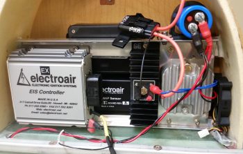
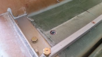
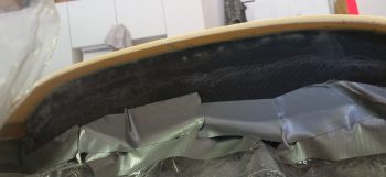
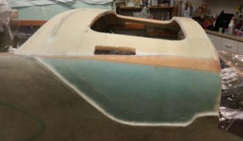
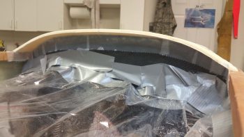
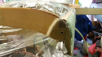
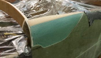
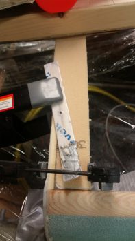
I honestly hadn’t planned on embedding the larger 60mm intake cooling fan but since I needed clearance for the headrest cover mounting CAMLOC tab just below the fan, it required me to move the fan up as far as possible.  With the fan surface mounted on the inside headrest sidewall, I couldn’t move the fan up since the SD-8 heat sink mount interfered with any upward positioning of the fan.  The only way that I could keep the fan in its optimized position for cooling the lower air-cooled components was to embed it in the sidewall as well, which allowed me to position it farther up and still provide clearance with both the SD-8 heat sink mount and the front cover CAMLOC mounting tab (shown set in position).

Yet another view of the embedded intake cooling fan.

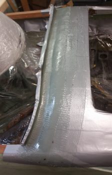
And the notched sidewall glass for the embedded intake cooling fan.

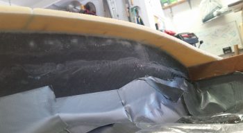
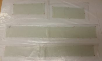
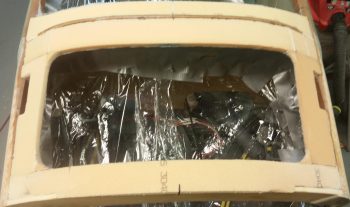
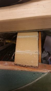
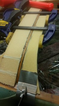
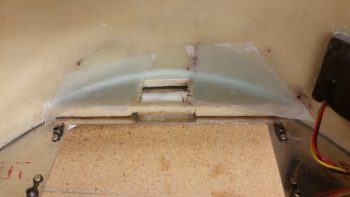
I then glassed in a square piece of BID that made up the “floor” of the cooling fan notches, and then added another piece of glass that actually covered the micro’d recesses I created on the sides of each notched hole.  I figured this would added a little strength back into the headrest structure at minimal weight.  However, this created a potential fitting issue if the glass on each side decided to be a bit thicker than required.  Also, to help keep the glass along the narrow edge of the sides of the notched holes, I simply taped up the fans to protect them and then inserted them into place to keep the glass positioned correctly.

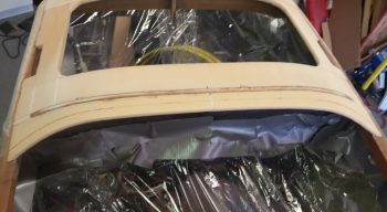
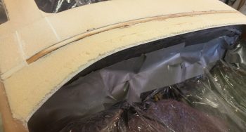
In the pic of the exhaust fan above, and below, are 1-ply BID reinforcement layups that I glassed in on the back side of the top plate reinforcement structure.  With the big hole that I dug out on the front side for embedding the Hobbs meter, I decided to add a bit more structural strength on the back side.  I can’t really add any glass on the front side since it would push the top plate out of position.

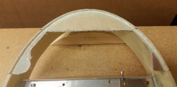
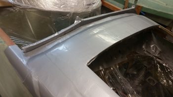
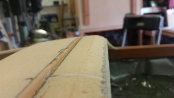
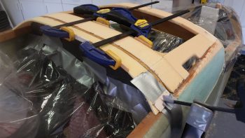
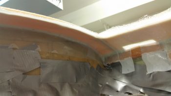
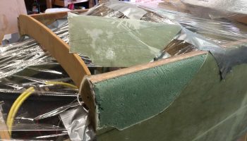
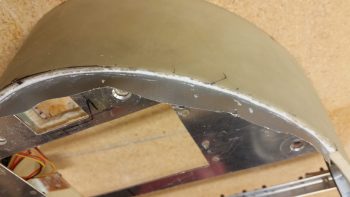
During the placement, sanding and alignment of the top plate, the interfacing edge of the headrest structure –being just foam– has been reduced to a narrow strip.  To get the foam edge back to its original thickness, provide a more seamless edge with the top plate, and to a degree finish the edge for paint, I decided to tape the edge of the top plate and then lay in a small bead of flocro along the headrest edge adjacent to the top plate edge.

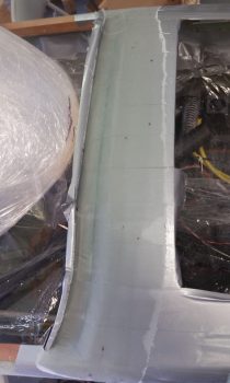
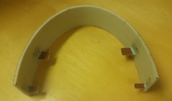
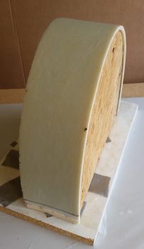
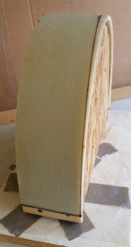
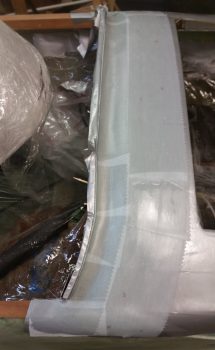
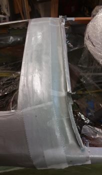
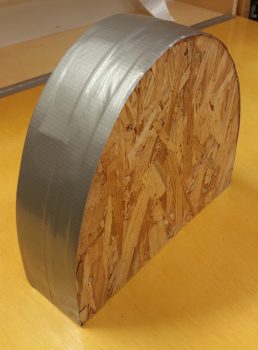
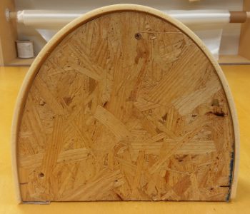
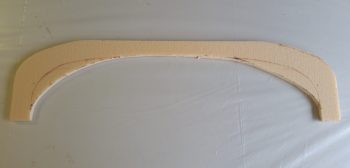
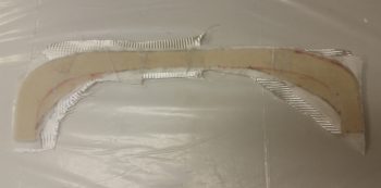
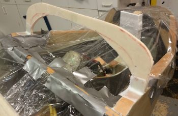
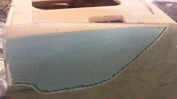
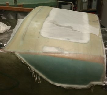
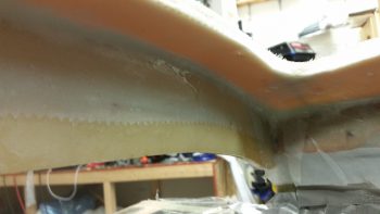
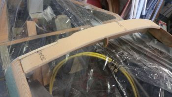
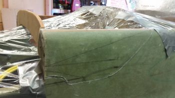
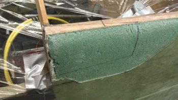
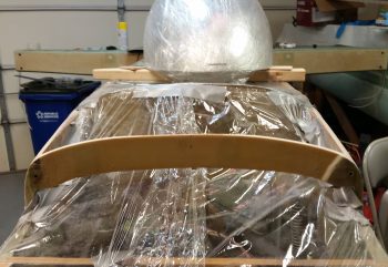
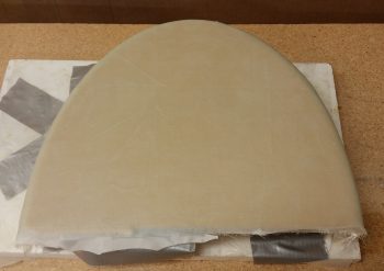
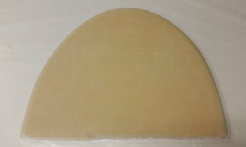
I then pulled the peel ply and razor trimmed the glass along the aft edge of the headrest front cover.  I will need to do some clean up sanding and aggressively sand along the edges to get a few bumps and slight irregularities knocked down in place.

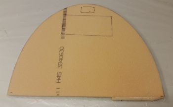
Here’s the aft side of the GIB headrest face cover plate.  Note that I will make some depressions in the aft side face before I glass it to ensure clearances with the internal components of the headrest, specifically the buttons on the front of the EIS4000 unit… which currently sit recessed below an imaginary line drawn across the face of the headrest’s front edges, but just barely.

So, I’m hoping that TOMORROW will be my half day on the GIB headrest structure build, and then I can get it glassed into the fuselage and move on with the nose and canopy build!


Chapter 18 – Just a headrest?!

Like I said in last night’s blog, today was another focus on the GIB headrest.

I started by finely sanding the front edge of the headrest so that it was even around the front edge perimeter.

I then set about determining the size and configuration of the headrest’s top plate, which I cut out of 0.040″ thick 2024 aluminum plate.  I then marked and cut a groove into the top half edge of the headrest that the top plate sits, and is mounted, recessed into… which is why I wanted the front perfectly “square” so that I could recess the top plate vertically, while the front of the headrest edge “leans” slightly aft being 3.9″ deep at the bottom base and 3.6″ deep at the top.  If you’re wondering, the aft edge of the headrest is vertical and straight.

I then measured out, marked and cut a mounting hole for the GRT EIS4000 control unit. Of course I wanted to see how it looked, so I mocked it up in the headrest and set the headrest in in place.

I then knocked out riveting the four #6 nutplates for mounting the EIS4000 to the headrest top plate.  I had to use the miniature version on the top holes so that the rivets wouldn’t peak out above the EIS4000’s mounting flange.  I will be painting this top plate, but I still didn’t want to mess around with covering up any rivets if I don’t have to.

I then tried out the nutplates by test mounting the EIS4000 into the headrest top plate… thankfully it fit fine and no issues.

I then glassed a piece of 3/8″ foam into the top of the headrest arch, and some scrap pieces of phenolic and G10 –respectively– inside the upper headrest sidewalls . . .  all which will serve as screw mounting points to secure the top plate to the headrest.  I used 2 plies of BID and started the layups on the aft side of the screw mounting tabs.  I taped up the top plate and used it as a type of jig to keep the tabs set at the right configuration, aligned evenly with the front edge of the recessed edge, not the front edge of the headrest.

As the layups above cured, I got to work locating and cutting both glass and aluminum mounting tabs for the 4 CAMLOC receptacles that will be used to secure the headrest front cover (not top plate) in place.

A bit later I pulled the peel ply and knife trimmed the 3 layups for the headrest top plate screw hard points.

Here’s the front side of the headrest showing the glassed in place screw hard points.

I then cut a very small trench in the foam around the perimeter of the front side of the top plate screw hard points and recessed inset.  Before I then laid up 1 ply of BID just inside the recessed inset where the top plate will get mounted into, I filled the trench with thick micro.  I then peel plied the layup(s).

Here’s a closer shot of the glassed front side top plate inset and screw mounting tabs.

I think I will have a few more hours on this GIB headrest before I finally get it glassed into place tomorrow, at which point I’ll transition into prep work on the nose and canopy builds.


Chapter 13/18/22 – A riveting day

I started off today checking my aft nose/avionics top deck actual glare shield layup.  I pulled the peel ply and it looked fine.  I’ll need to do some aggressive sanding to knock down a lump & bump here and there, but overall I’m very pleased with the results.

Today I wanted to take a big swipe at getting the internal components installation squared away on the GIB headrest before the structure gets glassed into place.  Yes, I know!  A bit of a rabbit hole to be sure, but yet just another sequencing thing that if done now will make the build progress much easier in the long run.  Definitely worth a 2-day detour in the grand scheme of things.

I started by checking, cross checking and double checking a myriad of final layout measurements.  I then cut out 4 each 1/16″ thick phenolic tabs for mounting aluminum angle cross-headrest mounts.  I then measured, marked and cut slots for the phenolic mounting tabs into the inner surface skin of the headrest.  I dug out the foam so that the outboard edge of each mounting tab sat flush against the interior surface of the outer skin.

Once all looked good, I sanded both sides of each phenolic mounting tab rough, flocro’d them into place and then laid up 2 plies of BID on the front side of each tab, and 1 ply on the aft side of each tab.  I then peel plied the layups, and after the tabs looked like they were set in their final position I took off to grab some supplies for glassing the nose and canopy, and to run a couple of errands (they weren’t set completely… and a couple moved a small amount on me).

A couple of hours later, after I returned from my mini-sojourn out, I pulled the peel ply and knife trimmed the glass edges.

I then spent the next 5+ hours finalizing the position of both angled aluminum mounting brackets, the respective components and the mounting bolt positions as I slowly drilled and riveted a BUNCH of nutplates into place.  Here you can see the backbone of the mounting setup in the GIB headrest: the top and bottom 1/16″ aluminum angle.

Here’s an aft view of the top and bottom aluminum angle mounting brackets with a bunch of nutplates riveted into place.  Quite obvious I guess, but for me personally I don’t want to mess around with the initially easier task of simply drilling a hole then using a nut & bolt to hold a component into place… I want to remove the nut from the equation and simply have to worry about the mounting bolt and that’s it.

Speaking of bolts. Since the access to the bolts around a good many of these components is very restricted, I opted to go with hex cap head screws that use an allen key for installation/removal.  Maybe it’s just me (I’m sure it often is!) but driving small diameter bolts/screws into nutplate assemblies with a screwdriver is just not an optimized endeavor and the amount of pressure required to avoid stripping the phillips portion of the screw head borders on just plain silly.

After getting the first round of #8 and #10 nutplates riveted into place, I then did a test mount of a bunch of the internal GIB headrest devices.  Note that this round of components all sit just forward of the two firewall face mounted MAP sensor boxes.

The components installed so far are as follows.  Back row: GRT MAP sensor (top) and Electroair EI MAP sensor (bottom).  Front row (l to r): Electroair EI controller, SD-8 backup alternator self excitation module (black heat sink), SD-8 voltage regulator mounted on 0.040″ thick heat sink plate, and SD-8 capacitor (big blue D-cell battery looking thing).

In the next pic after this one below I set the intake cooling fan in place, on the left (aircraft) side of the headrest next to SD-8 voltage regulator.  The smaller exhaust fan will be installed at about the 10-11 O’clock position when viewing the headrest as below.  Also, I clearly haven’t found a home yet for the rather robust inline 15 amp fuse (orange leads).

As you can see, it’s pretty tight quarters inside the ‘ol GIB headrest, and there still a number of components left to be jammed in there!  If you’re good at games like ‘Where’s Waldo?’ then you may have noted that I added the cooling fan into the mix, in the lower right hand corner (of the pic)…. actual left hand corner of the headrest.

Here’s a view from a higher up angle . . . again note how it makes the headrest structure appear very round!  Also, if you hadn’t noticed it already, take a look at the red & black twisted pair wire exiting the GIB headrest structure via the wire transit hole.  Just an example of how the wires heading to the hell hole or points forward will exit the GIB headrest.

Engine specific wiring will exit through the firewall in one of two pass-thrus, situated in the respective lower aft corners of the GIB headrest . . . coincidentally, that’s why the MAP sensors are center mounted, to allow open wire paths to remain clear in both aft left and right sides corners of the GIB headrest.

And a side view showing a bit of depth on the installed headrest components so far.

Tomorrow I’ll do round two of component install on the GIB headrest.  I’m not really too concerned about the front cover since I’ll have access to glass in tabs, rivet nutplates or CAMLOC receptacles towards the front edge of the GIB headrest housing.  Clearly the tabs I just installed and glassed in place would have been immeasurably more difficult if I had tried to do them with the headrest structure already installed.  If all works out well tomorrow, I’ll most likely glass the GIB headrest structure in place atop its CS Spar perch and affixed to the front face of the firewall.

As stuff is curing I’ll also start doing some prep for both the nose and canopy structure builds.


Chapter 13/18 – If it doesn’t move…

Glass it!!!

I started out today by getting the first of many things curing.

Since I will have a myriad of electrical components housed in the GIB headrest, I am completing the task I started when I populated and configured the Hell Hole before mounting the firewall.  The task here is to drill a wire transit hole through the top of the CS Spare (not the spar cap area of course) by first reinforcing the sides of the eventual hole with flocro, and then create the hole.

I started by identifying exactly where the wire transit hole was going to be located.  My aim was to get it as close to the front right interior corner of the GIB headrest.

I then drilled out a good side sized hole ONLY on the top surface of the CS spar. I then dug out a good plug of foam to allow me to replace the foam with a 50/50 mix of flox and micro.

Here the flocro has been put in the hole and is curing.

I’ll jump ahead here well over an hour into the future to show that the flocro cured and I drilled a final 7/16″ hole through what will be the GIB headrest “floor.”  The area surrounding the hole will get further reinforced with the interior 2-ply BID tape that I’ll layup when I glass the headrest in place.

I then got to work on the GIB headrest.  I pulled the peel ply and sanded the surface where any imperfections where apparent.

I then marked the glassed GIB headrest for cutting.  The top depth is 3.6″ while the bottom depth is 3.9″.

After cutting the GIB headrest with the Fien saw, I then test fitted it in place.

Not shown is my spending about an hour measuring, test fitting, ascertaining, and determining final component placement inside the headrest.  One thing became quickly apparent to me, and that was no further steps could really be taken on the headrest until the inside surface was glassed.

So I laid up 1 ply of BID on the inside surface of the GIB headrest, and then peel plied it.  I then set the headrest back into place and taped the edges so that it was in what would be its final shape.  Another view I didn’t capture on camera was that if the headrest sides weren’t kept in check, then they would splay outward.  I figured an inside layup would keep the sides where they needed to be, and allow further interior component install steps to be taken.

While the GIB headrest interior layup cured, I then cut the B&C recommended heat sink and mount for the SD-8 alternator’s voltage regulator.  Again, according to B&C, a 0.040″ thick heat sink would do the trick, so that’s exactly what I used in the 2024 aluminum variant of metal.

I then measured/added/riveted a couple of K1000-4 nutplates to the SD-8 voltage regulator heat sink mount for the SD-8.

Here’s the back side of the SD-8 heat shrink mount showing the nutplates riveted into place.

And a shot of the SD-8 voltage regulator being test fitted onto its heat sink mount.  I think this heat sink mount should do the trick nicely.

I then set my sights on the last task of the evening: glassing the aft end of the avionics top deck cover which is technically the actual glare shield.

I started by adding a urethane foam shelf that stuck out from under the glare shield sub-structure by 0.9″.

I then added a taped foam wall on the aft side that will create a lip on the aft edge of the glassed glare shield once it cures.  This lip will both interface with the canopy front skirt as an ad hoc interlock and will also serve as a drip guard/block to keep any incoming moisture diverted to the outboard edges of the canopy skirt.

I laid up 3 plies of BID in what will be the bottom (interior) surface of the aft nose/avionics top deck cover.

My layup for these 3 plies of BID had the first ply going on at 4.5″ wide, with the next ply at 3.5″ wide, and the final ply at 2.5″ wide.  My primary focus was on the aft “trough” side of the layup to ensure that all 3 plies were laid up well to create a strong glare shield, especially since it will have a structure consisting of nothing more than cantilevered glass.

Again, to reiterate, these 3 plies are the bottom/inside surface of the very aft edge of the avionics top deck cover, so more plies will be added to these as the top cover is constructed.

To facilitated the construction of the top cover –including the addition of more plies to this layup– I peel plied the layup.

Here’s another couple shots of the peel plied glare shield layup.

After the final glassing of the evening above, I then grabbed the GIB headrest, pulled the peel ply and razor trimmed the edges.

As per my discussion, note how the interior layup allows the GIB headrest to maintain its appropriate shape.

I then set it back into place –sans any tape at the bottom edges– to check its fit.  I have to say that I’m liking what I see so far!

[Note the position of the GIB headrest wire transit hole…]

Tomorrow I’ll continue with my nose and canopy install related tasks.


Chapter 13/18 – Mysteries Revealed

I started out today submitting an order to ACS primarily for some more aircraft oil to replace the oil I lost out of the engine during the Great Oil Spill Disaster of May 2018. Since I was submitting an order anyway, I took a good half our to review my wheel pants 1/4-turn fastener requirements and added some more CAMLOC/SkyBolt fastening components to my order.  I should just need one more final order on my wheel pants fasteners after this order when I do the first real install of the hardware and figure out my final requirements.

I then got into the shop and started off by narrowing the fuselage-side mounted lower hinge lock assemblies for the avionics top deck cover.  After narrowing them, I drilled thru-holes for the flox to grip the hinge plates better.

I installed the hinge pin (for the right side I used finishing nails) and then taped up both the inside and outside corner, with the upper hinge lock assembly in the vertical position… 90° to the hinge locking plate that was getting floxed into place.

I then floxed in the lower hinge locking plate on each side.  After each plate was set in place with flox, I then made up a 4-ply BID prepregged layup for each side measuring 1.4″ x 4″ to secure the lower plate in place on the underside and overlapping onto the fuselage sidewall.  Before laying up the glass I added a flox fillet in corner at the intersection of the underside hinge plate and the fuselage sidewall.  I then peel plied the bottom edge with a 1″ strip of peel ply.

A few hours later I pulled the peel ply and removed the upper hinge lock assembly.  Kind of a funny oops was that on the left side I can’t get the hinge pin out since there’s no clearance!  No worries since I’ll need to drill a hinge pin hole through the instrument panel anyway.  I would like to point out that the hinge pin is at the exact spot I was planning for it to exit through the panel.

Here’s the upper hinge lock assembly back in place, in a down position to be able to see it better.  To be clear, no “hinge” swivel action will be taking place with these hinges, they are simply locking devices to keep the avionics top deck cover secured in place.

This is actually a better representation of the upper hinge lock assembly since it will be pointed upwards in final configuration.   Once the cover is completed and in place, this hinge lock assembly will be riveted to a tab hanging down from the underside of the cover.

I then spent another good half hour assessing and pondering exactly what methodology I was going to use to create the top cover.  Throughout the past number of years as I have planned to have this aft nose/avionics top deck cover, I have considered the standard adding-then-shaping-foam method.  Of course that called into question on exactly what type of foam to use? Blue, urethane, or pour foam? Or even a thin layer of PVC foam?

I also considered a straight glassing method, but then while it is simpler, it doesn’t allow for contour shaping which is something that really needs to happen.

Then, as I was moving stuff around in the shop this past week, I ran across some 1/16″ thick x 4″ wide strips of Balsa wood . . . hmmm?  Could I? . . .  interesting.  Well, after playing around with the strips of Balsa wood, mystery #2 was revealed in just how to get the aft nose cover constructed: Balsa wood!  Yep, with the avionics top deck sub-structure already at the proper angle, and my having sanded both sides to match in elevation, the Balsa wood strips will easily hold their shape spanning the avionics access hole and be flexible enough to contour to the surface of the avionics top deck. That will give me about 80% of the cover’s surface with just the area on each side forward of F28 up to the intermediate nose bulkhead to contend with… which I’ll simple shape foam in the more traditional method at these points.

With plan in hand, I worked it through a number of times in my noggin until I flushed out the various kinks and got a good handle on the sequencing.

As a point of note, the aft nose/avionics top deck cover really isn’t a huge cover and is just a bit over 2′ long from front to back.  And about 2′ wide of course from side-to-side.  The cover will have a minimum of 10 attachment points, but most likely 12 when completed.

The last mystery to be revealed (#3) was the GIB headrest construction.  I had pondered about this one too off and on over the years since I knew I wanted my GIB area to be patterned after Wayne Blackler’s GIB headrest.  No offense meant towards any Long-EZs out there, but the plan’s method of creating a cavernous amphitheater-looking structure back there was not something I liked in the least.  Yes, Wayne’s version adds a bit more foam and glass, but I much prefer the look of Wayne’s GIB headrest/aft canopy structure vs stock plans.

I will say that my GIB headrest structure will be just a tad smaller than Wayne’s by about an inch around the sides.

Again, I pondered, dreamed and aspired to reach the . . .  oops, different story! Ha!

Yep, I wondered how the heck I was going to glass this structure while keeping its shape. Well, after spending a good 45 minutes finalizing how all the internals will fit, and using a very minutely modified version of the template that I created back in 2012, I simply cut out layers of scrap wood to create a form (or plug) for the foam.

Since we’re not talking about a hugely robust nor super high strength structure here, and since space was fairly critical –not to mention in short supply!– I went with 1/4″ thick PVC foam for my GIB headrest structure.  Moreover, the 1/4″ foam would easily wrap around the wood plug without cracking… and without any required cajoling (read: heat gun!).

Just for fun, and to punk some GIB applicants [Final approval still pending . . . ] with my clearly comfortable headrest design <grin>, I did a quick mockup of the headrest plug.  If you’re wondering why the plug is taller than the firewall it’s because I added heigh to it to make the sides a bit longer to allow me to secure the foam at the bottom of the plug with screws.

I then taped up the plug to protect it, but even more so just to level out the surface a bit.

I then cut the 1/4″ foam and secured it to the form/plug with a couple of screws at the bottom on each side.

This front shot looks like the bottom edges distinctly curve in, but that’s a bit of an optical illusion since the camera is at a downward looking angle.  Kind of a neat effect since the bottom edges are actually fairly straight!

I then cut out and laid up 2 plies of BID on the GIB headrest foam.  Boy, I’ll tell you, as an avid prepregger this free glassing stuff is for the birds!  What a PITA!  I thought I’d go ‘ol skool and just slap a couple of plies of glass on there . . . man is it high maintenance and finicky without that plastic keeping it all wrangled and in place.

Lesson learned!

I then peel plied it of course.  I took the pic above because I really do like the look of the non-peel plied weave in fiberglass, but when it comes to adding more plies, finishing and painting, it’s a pain to have to sand it to get the glossy cured finish knocked down… especially inside the weaves.

Tomorrow I’ll continue to work my headrest and start the prep for the aft nose cover, forward nose foam structure, and canopy install.


Chapter 13/18 – Strike Plates… bam!

Today was a bit more even paced than yesterday, but I still got some significant stuff done.

I started off with a good sanding of all the edges and surfaces of the Avionics top deck…

which I guess is now a hatch as well.

I then got to work estimating the sides/corners and middle open area of the nose intermediate bulkhead.  I started to cut the middle open area with the inside edges positioned much farther out before I reiterated to myself that there is a significant transition from the aft squarish-shaped nose cross-section to a much more round cross-section the further forward the nose goes.  So I added some mass back in since most likely it is the outer “corners” that will get shaved off during the nose build process.

I then mocked up the intermediate bulkhead.  Again, this intermediate bulkhead is the demarcation line in that everything forward of it is “standard” nose and everything aft of it lies under the aft nose/avionics top deck cover.

I then glassed the aft side of the intermediate bulkhead with 1 ply of BID and peel plied.  If you’re wondering about the front side of the intermediate bulkhead, it stays in raw foam form since it will combine with other raw foam to make up the forward nose walls.

I then got to work on some of the hardware that will be used to secure the cover to the aircraft, as you see here with these hinge assemblies.  The 3-ring hinge assemblies will be attached to near-vertical tabs that extend down on the underside of the cover and then extend through the Avionics top deck via the 2 slots that look like hand holds on each side (see both top pics above).

The 4-ring hinge assemblies will be floxed & glassed in horizontally to the underside of the longerons, just aft of the longeron doublers and extensions (directly underneath the slots mentioned above).  These obviously are the aircraft side of the hinge lock pin equation.

Also mounted on the fuselage-side are the two strike plates on the left of the pic below. Each of these will be mounted to the inboard “face” of their respective longeron and will be what the upper (cover) hinge lock assembly hits first, at a very slight angle, which then pushes the cover’s hinge lock assembly inboard a bit until it clears the strike plate and then snaps into place –interlocking– in the lower fuselage side hinge lock assembly.  The hinge pin will then be pushed forward from the instrument panel side to lock the upper and lower hinge lock assemblies together.

Besides wet flox, the strike plates will be held in place by a countersunk aluminum rivet on each side, used as pins inserted into small diameter holes drilled into the longerons.  The strike plates are made up of 0.040″ thick 2024T3 aluminum and measure 1″ x 3″.

I then floxed the hinge strike plates to their respective inboard longerons and spread clamped them in place.

Here’s a closer view of the left strike plate floxed and clamped in place.

After pulling the peel ply and trimming up the layup on the intermediate bulkhead, I micro’d and glassed it to the nose sides using 2-ply BID tapes on both the front and aft corners.

Here’s another shot of the intermediate bulkhead (sorry for my POS camera!).

And here’s a wider angle shot showing the clamp holding the floxed strike plates to the longerons and the intermediate bulkhead glassed in place.

I had planned on doing a few more layups, but my better judgment actually won out tonight and said to break a littler earlier than I normally would.  I’d be working on the avionics top deck area and I wouldn’t want to inadvertently hit the intermediate bulkhead while it’s curing.  I have it spiked in place with toothpicks, and the measurement has stayed locked on like a laser sight, so I’m not going to mess around with a good thing. Plus it’s late so I’ll finish up this post and call it a night.

As I mentioned, I have a few more cover prep layups to do on the avionics top deck, and then the rest of tomorrow will be geared towards construction of the GIB headrest/component housing.  I’m constructing the GIB headrest at this point because I want to have it mounted prior to the aft canopy frame going in.  Plus, once I say I’m finished with the nose and the canopy –as I mention in my update– I want pretty much anything associated with the nose and canopy to be as completed and installed as possible.


Chapter 13/18 – Avionics top deck

Is what I’m now calling the aft nose/avionics bay reinforcement structure.  It just flows better.

Ok, so today I started out with a couple of orders.  First off, I ordered the Trig TT22 Transponder serial connection adapter from GRT Avionics.  This adapter allows the HXr EFIS to control the remotely mounted Trig TT22 transponder.  With this adapter in hand I now have all the avionics I need to be legal for any initial flying for my 40 hour fly off.

My next purchase was a result of my effort to find a different model LED dimmer as a replacement for the one I fried.  After looking around off & on for the past couple of months I just did not find a suitable substitute, so I bit the bullet and pulled the trigger on this one from Stein Air since I was ordering some other stuff anyway.

I then went down to the shop and finalized the cleanup of the Avionics top deck underside layups.  Again, these layups won’t win any beauty awards, but they are functional and strong, so I’m going to call that a win…

I then did the same for the underside layup on the glare shield substructure.

I marked a bevel line 0.6″ forward of the glare shield aft edge, but before I did anything with the glare shield I sanded down the high points on the Avionics top deck reinforcement foam in prep for glassing.

Here we have the bevel line that I marked on the top side of the glare shield 0.6″ forward of the edge.

I then beveled the edge on the glare shield substructure edge and then removed the foam at the edge creating a small “trench” to expose the glass underneath.  I then sanded the glass in prep for adding flox in the “trench” to facilitate a better glass-to-glass type bond.

Here’s a better view of the beveled edge & “trench” on the glare shield substructure.

I also created a narrow “trench” on the edge of each fuselage sidewall depression to also increase the strength of the bond at the intersecting glass.

With my avionics top deck foam structure in place, I did a quick final check of my nose profile.  I like it!

I then spent a bit of time both determining/finalizing my layup schedule and cutting the glass.  The layup schedule sequence starts from the bottom of the pic below with a ply of UNI (lower left) that starts on the front side of the fuselage sidewall depression and travels across the front avionics top deck foam reinforcement and then stops at the opposite fuselage sidewall depression.  Then another wider ply of UNI (lower right) was laid up at the aft end of the avionics top deck, essentially across the aft foam reinforcement piece and the instrument panel top edge.  It too is laid up from one side of the fuselage sidewall depression to the other.

The next ply –the first full ply of BID– consists of the 4 middle pieces of glass, with the visible fuselage depression-shaped pieces going in and then essentially “cross strap” pieces going across the top.  The seam for these pieces is parallel to the aircraft centerline.

Finally, the last (top) ply of BID is the 2 pieces at the top in the pic below.  The bottom of the 2 pieces gets laid up on the front side of the avionics top deck, with the top piece getting laid up last, overlapping the front piece by a good inch. The seam for these pieces is perpendicular to the aircraft centerline.

And here’s the Avionics top deck foam reinforcement structure glassed and peel plied.

I then ran out and grabbed dinner, beers and a movie with my buddy Rob.  When I returned and checked the layup it was ripe for final steps, so I pulled the peel ply and razor trimmed all the edges.

Tomorrow I’ll edge sand all the rough edges, but I of course got the lion’s share of glass trimmed off the layup tonight.

Here’s a couple shots that include the fuselage depressions for the avionics top deck nose cover.

I’m very happy with how this layup turned out, and even more happy that I can finally REALLY start in on the nose and canopy build now with this preliminary task out of the way!


Chapter 13/18 – Nibble, nibble, nibble

Here’s a shot of my starting point today with all the avionics bay foam reinforcement pieces in place.

Clearly I was missing the right side glare shield 1/4″ foam substructure.  When I claimed yesterday that I had no backside clearance for nails, it dawned on me this morning to not let the nail holes go to waist and use toothpick tips as wooden spikes in the same manner as we did when we build the canard!

I then floxed/micro’d the right side glare shield 1/4″ foam substructure in place.  I have to say my wood “spikes” worked a treat!

So, here’s a shot of all the aft nose foam in place.  From here on out any foam that is added will be a permanent part of the external nose structure (as versus the cover).

Here are a another few shots of the avionics bay reinforcement foam structure and the foam glare shield substructure.

I took a wider angle shot to show how the progression of the nose is coming along.

I then spent nearly an hour cutting glass. I then prepregged and wet out 2-ply BID tapes for the underside layups of the avionics bay reinforcement foam structure.

Here you can see the over (or under!) hanging glass of the avionics bay reinforcement foam structure layups.  I was on the fence about peel plying the layups, but it is so hot and humid that the glass seriously wasn’t overly interested in sticking to the wet micro’d foam! Using peel ply was magic and kept the glass wrangled and right in place!

Here’s a smattering of pics showing the BID layups on the underside avionics bay reinforcement foam structure.

After the underside avionics bay foam reinforcement structure was glassed and peel plied, I then set my sights on the 2-ply BID layup for the underside of the foam glare shield sub structure.  Again, I most definitely peel plied it as well!

Here’s another lower angle shot of the 2-ply BID layup on the underside of the foam glare shield sub structure.

My last official act of the evening was to razor trim the avionics bay reinforcement foam underside layup glass edges.

Tomorrow, my goal is to get the top side of the avionics bay foam reinforcement structure and the glare shield sub structure glassed.  After that, I can move on with the “standard” (LOL… right!) nose and canopy build.


Chapter 13/18 – Heresy continues!

I started off today by clearing off the big, convoluted pile ‘o stuff off the floxed/micro’d in forward avionics bay cover reinforcement piece.  I was quite pleased with how it came out.

A couple of reminders on this thing.  First, this piece is the first of 4 pieces to get installed. Just think cardinal headings and you get the gist.  Next up will be the aft piece that attaches to the top front edge of the instrument panel.

Next, when all 4 pieces are in place, interconnected, and glassed, this area will provide reinforcement from one fuselage side to the other and replaces the top foam avionics deck/aft nose cover that the plans says to glass in place just forward of the instrument panel.

Lastly, this forward piece specifically also serves to increase the height of F28 about 0.4″ to allow for a better flow of the top nose profile and removes a flat spot that was apparent in the nose contour.

Here’s a view from the aft side of the first of 4 pieces to go in around the perimeter of the avionics bay.

Before I went any further, I took a good half hour to ensure that the right side top forward longeron & F28 were trimmed, sanded and shaped to match the left side.  As per my usual response, they’re not perfectly matched, but pretty darn close.

Here I used a Sharpie as a sanding guide coat to “flatten” the top side on the right to better match the left side.

Pardon the bright sun in the background, but here’s a decent depiction of the top nose section “corner” curves now.  Much, much better than they were before and I’m very pleased with how they turned out.

I then cut, shaped and floxed in place the 3/8″ thick x 2.2″ wide PVC foam piece to the front top edge of the instrument panel.  Since this too has the apparent requisite pile ‘o crap on top of it to hold it all down in place, I grabbed a shot from underneath.  It’s the first foam structure visible just above the gray tape line… and a bit more visible on the right side of the pic.

To get the foam to behave, especially on the outboard edge curves, I drilled a series of small holes along the top edge of the instrument panel and used nails to keep the foam aligned properly.

Here’s a view of the right side reinforcement foam piece.  As you can see I cut relief lines in the foam, although this piece actually snapped off entirely at the top relief line as I was setting it in place.  No worries of course since I just micro’d it in place.

And here’s the aft foam reinforcement piece, or rather the pile ‘o crap securing the aft foam reinforcement piece.  This is #2 of 4 pieces with the side pieces coming up next.

<Fingers snapping> Voila!  And here are the side pieces almost completely in place. If you look closely you may be able to see that the front inboard corners are sticking up about a foam’s width high, due to the shape and curvature of the nose.  I floxed/micro’d both side pieces in at the aft side and about 2/3rds of the way down the aft outboard edge (to the longeron) and will let them completely cure before making the minor twist at the front edge to secure the side piece to the front cross foam piece’s aft edge.

This is a very good shot showing the access I’ll have to the avionics through this hole created by the 4 foam edge pieces.  Yes, this access hole is significantly larger than what many builders have done by creating an access hatch in this area of the nose.  I honestly feel (IMO of course) that once the glass is in place that there will no loss of structural integrity in this area, especially when the cover is secured in place.

Here you can see –about 5 hours later– I’ve micro’d (foam) and floxed (foam to longeron) the front of the side foam piece to the front cross foam piece’s aft edge using a nail to align and secure the 2 pieces.  The clamped on vise grip is to induce a slight twist to get the outboard edge to pivot up a hair (about 0.050″) –using the nail as the fulcrum– to better align the side foam’s outboard edge with the longeron, elevation-wise.

The slot in the side foam piece (on both sides) is for a length of structural hinge that will be attached to the underside of the aft nose/avionics bay cover on a vertical tab and will align and attach to an interlocking length of structural hinge that will be floxed/glassed onto the underside of the longeron.  The hinge pin will be modified with basically a set screw on the aft end that will be secured into a threaded point on the instrument panel, one in each upper corner of the panel.  When the cover is to be opened, unscrewing the hinge pins and sliding them aft will complete the hinge pin removal step.

[There will be a circlip on the hinge pin assembly that will A) not let the hinge pin be removed (or lost) from the panel without specific effort, and B) not let the hinge pin exit the aft-most tab on the longeron mounted hinge assembly, thus ensuring the hinge pin assembly is always ‘locked & loaded’ alignment-wise and ready for pain free insertion into the aft nose/avionics bay cover’s hinge assembly once the cover is closed and the upper hinge bracket drops into alignment with the lower hinge bracket].

After a LOT of assessing, measuring, research, assessing, cardboard mockups, more research, more measuring, pondering, etc. I finally came very close to the final configuration on the plan for the interface of the nose/avionics bay substructure, the aft nose/avionics bay cover, and the front canopy skirt.

With my researched and tested plan in hand, I got to cutting some foam.  First up was the 1/4″ thick PVC foam that will make up the BOTTOM, permanent glare shield substructure. I was originally going to just use a number of plies of glass for the glare shield sub structure, but I needed a bit of depth from the top of the instrument panel to create a drop down edge going aft for the front canopy skirt to seat onto/into.

The 1/4″ thick foam is a compromise for getting some depth/thickness for the glare shield and also the max thickness of any intrusion of the instrument panel’s perimeter in regards to both the physical clearance of panel components and visibility of the panel.

You’ll see later on that the front edge of this 1/4″ glare shield sub structure will get beveled at an angle going forward, and will support the aft nose/avionics bay cover that will follow that beveled edge and create a lip going aft of this foam (and glassed) glare shield sub structure to sit under and “interlock” with the bottom edge of front canopy skirt.

Also, as a point of note, the permanent glare shield substructure will be where the strip of blue LED cockpit lights are permanently attached to… so that the lights are tucked up and out of the way..

The front-to-aft depth along the majority of the foam glare shield substructure is 1.3″, while the flare at each end is 2.4″ thick.  My estimation of total foam width (accounting for the down curve and angle at each end) during foam cutting was about a half inch too long, and since each outboard end was specific in design and the middle area was static in its 1.3″ width, I had to cut about a 1/2″ out of the middle and install the glare shield foam as 2 separate pieces.  Since I have no “backside” real estate for nails on this go around, I tried to hand jam it with flox and some 5 min glue dabs along the length.  Well, the 5-min glue sorely disappointed and I ended up scrambling to clamp it and weigh the left half 1/4″ foam glare shied substructure piece in place.

It was late so I’ll let the left half cure before tackling the right half tomorrow.

Again, I’ll continue to work the nose substructure for the aft nose/avionics bay cover and the interface with the forward nose structure and aft canopy structure as well.  I have to say that in my research on the interface between the substructure, cover and canopy I stumbled across some gems of knowledge that will greatly help in constructing the canopy frame (regarding canopy frame rail width).

Creating a modification such as the aft nose/avionics bay cover is always slow and time consuming, not to mention quite maddening at times, but I really feel that having to take about 5 minutes to deal with hardware removal and then being able to rotate a cover forward to expose and provide access to the avionics bay and F28 forward/canard mounted items such as GPS antennas, airspeed switches’ adjustment screws, etc. . . . all pretty much on the fly and on demand will be quite worth this mod.

Moreover, it will clean up the external flow and look of the nose since I will have only one large hatch and then only one other break in the nose at the forward edge of the cover, just forward of the canard.  In addition, it allowed me to do the top canard tab long bolt attachment mod which although clearly not a mandatory mod, is definitely my preference.  Finally . . . yes, to be fair, I will add a couple of break lines on each forward fuselage side between the aft edge of the elevator/canard to the instrument panel edges.  These breaks (and the increased build time!) are honestly the only downside to incorporating a cover on the nose.


Chapter 6/13 – Yep, I did it!

I started off today taking a gazillion more measurements, and checking out other builders’ sites on their canopy positioning and inboard elevator root fairings.  After getting my comfort level significantly higher on the whole of the plan working (at least on paper!) I got to work cutting out some 3/8″ PVC foam.

The first piece was for an intermediate bulkhead that I’m going to install just forward of the canard, which will look bow-shaped and will essentially serve more as both as a bit higher strength cap to the blue foam going in forward of it, and as a demarcation point for the avionics bay/nose cover going aft.

And yes, you read that correctly.

I will be incorporating a flip-up/removable cover for the canard and avionics area forward of the instrument panel and aft of F28.  It will also overlap the panel going aft so that the canopy will physically lock it into place when closed (that of course is not the only securing method on the aft side).

More on the avionics bay/nose cover below, for now here’s another view of the intermediate bulkhead that I’ll be securing into place before the nose foam is put in place.

I also cut out a 1.8″ wide strip of the 3/8″ PVC foam that will be the front piece of what is roughly a picture frame looking foam rectangle that will be floxed and glassed in place for torsional strength of the upper forward fuselage between the panel and F28, and the upper longerons on each side.  It will essentially be an interconnected “C” channel (just sandwiching foam in this configuration) around the entire edge of the avionics area, with all the glass locking the 4 sides (and corners) together.

Another shot of the nose/avionics bay reinforcement piece, which is the first of 4 separate side pieces to be installed.  This design will allow for a significant opening in the top for access to the avionics forward of the panel, which will all be enclosed by the removable cover that extends from the front edge of the canard to just aft of the instrument panel.

I’m aware that this design is deemed a bit controversially by some builders and Canardians, but I’ve studied a number of designs and am mitigating any induced weaknesses to the airframe structure by implementing it.  In fact, I honestly think that my design will be significantly stronger that either the plans version or by simply having an avionics access hatch cut in the top of nose just forward of the canopy/instrument panel.

Part of my decision process today was to come to a final conclusion on exactly the design and configuration of the sides of the aft nose and avionics bay cover.  My design uses some what of a split elevator fairing where the fairing itself is integral to the cover and then secures to a very robust bottom segment of the fairing via a screw up through the bottom securement tab into an embedded nutplate on the underside notched portion of the fairing.

Where the trailing edge of the elevator fairing intersects the fuselage sidewall and the inherent transition fillet on the underside of the fairing where the determinant dimensions for both the aft and bottom edges of the aft nose/avionics bay cover sides.  After RE-reviewing a number of Berkut, Long-EZs and Dave Ronneberg designs with nose hatches, I settled on a simple angled transition from cover to fuselage at the instrument panel external fuselage area.

I double and triple checked all the possible associated variables and potential issues I could think of, and then I made the plunge.  I made the final design version on the left side of the fuselage, then traced it to transfer it to the right side.

Which you see is completed here . . .

I then took my wide roll of packing plastic and wrapped up the nose from tip to instrument panel to protect the innards from errant fiberglass, foam and other nasties.

I then loaded a fresh blade on my Fein saw and got to work on my respective fuselage sidewall surgeries.  My goal was to cut just enough in depth to cut through the glass and not get into the foam underneath.

If I had any doubts as to how secure my glassing was on the fuselage, this endeavor laid that to rest.  It took a good 20 minutes minimum on each side to get the glass pried off while being careful not to damage the foam underneath.

The action here was actually a 2-part task in that not only did it expose the areas on the upper/forward fuselage sides that will allow me to create depressions for the aft nose/avionics bay cover, but also to correct my previous non-shaping of the front “corners” of the fuselage that should have been significantly rounded over before the fuselage exterior was skinned.

In the summer of 2012 I glassed the exterior of the fuselage without having caught the requirement to round the very front of the longeron and nose sidewall foam, as you see that I’ve just done on the right side (left pic below) vs the way I had it (right pic below). Yes, I was living in blissful ignorance until Marco went to glass his fuselage, at which point he queried me about it.  I gave him my incredibly well thought out reply of, “Huh?! What are you talking about?!”  Followed a bit later by, “Ah, <enter appropriate expletive here!>”  To see a great explanation of this, check out Marco’s blog.

As for the aft nose/avionics bay cover, I will be laying up glass back onto this exposed foam area with overlap back onto both the existing fuselage sidewall glass and onto the new aft nose/avionics bay front reinforcement structure (“picture frame”) that will be in place between the panel and F28, and the longerons on each side.  This will serve not only to replace the structural element of the previously removed sidewall glass, but tie the fuselage sides to each other via the reinforcement structure.

So here’s my shaping the forward top longeron intersections with F28, with the right side (left side of pic) nearly finished and the left side still untouched.

I then finished the forward top longeron shaping to about 90%.  I still have to do a tad bit more dialing-in so that both sides match in shape, but it was late, I was tired of sanding and sanding with a hard board is amazingly loud, so I wanted to take it easy on my neighbors and finish the final 10 minutes worth of sanding tomorrow.  I also need to finalize the depth of my sidewall depressions in the exposed foam.

Here’s another shot of my shaping the forward top longeron intersections with F28, with both sides shaped this time around.

Yes, I should have taken a picture of my shaping and prepping of the aft nose/avionics bay front reinforcement piece before I floxed/micro’d/5-min glued it in place. This pile ‘O stuff is simply to keep the various parts of it weighted down <correctly> since the aft end of this piece is ever so slightly raised to match the downward angle from the panel to the F28 bulkhead.

This contraption (aka “convoluted pile of crap”) right here is exactly why I decided to set the 4 sides of this internal reinforcement frame in individually, since the installation of each side/edge has it’s own unique requirements and challenges.  Once all the pieces are floxed/micro’d in place, I’ll do a final sanding & shaping of the new “one-piece” structure and glass it in place as one unit.

Here’s a straight on view of the aft nose/avionics bay front reinforcement piece.  As you can see, the center section is situated and mounted on the top edge of F28, where the outer 30% on each side is then even with the top edge of F28.  This gives me just a tad bit more height in the center area of F28 for a good nose angle flow from the panel to nose tip as it traverses F28.

And a couple more shots of the aft nose/avionics bay front reinforcement piece on the left side.  The transition from the piece being on top of F28 to simply adjacent F28 is underneath the taped popsicle stick securing the bonded mating surfaces, but you can make out the foam piece floxed in place at the F28-longeron corner junction.

Tomorrow I will continue my work on the nose structures to get them installed and glassed in prep for starting on the actual nose structure and nose cover build. I would estimate in the next couple of days I will also start on some preliminary canopy installation tasks.