Chapter 13 – Bait & switch

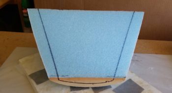
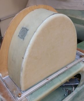
As I was having my morning coffee I was thinking about the tasks that lie ahead of me for the canopy build today.  I realized that for the very front of the canopy, the front skirt, that if I didn’t have the Aft nose/avionics top deck cover glassed that the skirt on the front underside would be off a bit.  But then I reasoned, “How much?”  I mean, we’re seriously only talking 2 plies of BID more [so I thought at the time] for the final glassing of the aft nose cover/glare shield . . . that’s not a huge thickness to contend with.

Ahh, but then I thought about accessibility.  You see, I need the aft nose cover in place to glass in the canopy front skirt.  Conversely however, if I don’t finish the cover first and then proceed with the canopy, then I’m locked out of working on the nose cover since the aft end of it would be covered by the canopy front skirt!

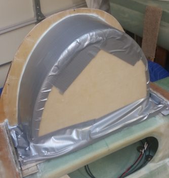
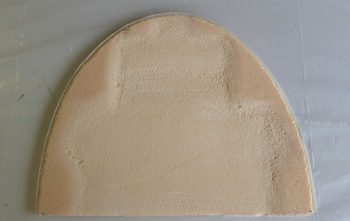
A pickle to be sure, but both issues resolved by simply knocking out glassing the final layup on the exterior of the aft canopy cover.  Plus, since around 41 hours had passed since I finished the initial construction/glassing of nose cover, I figured it was plenty cured.

So that’s what I did.

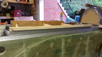
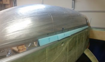
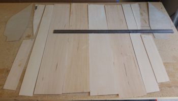
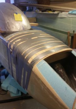
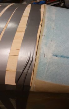
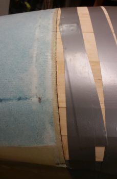
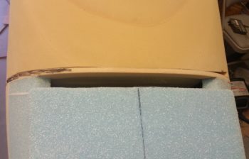
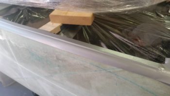
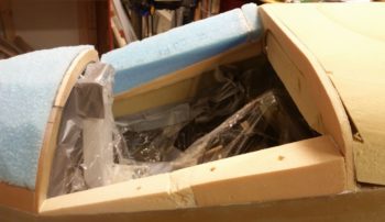
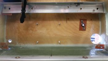
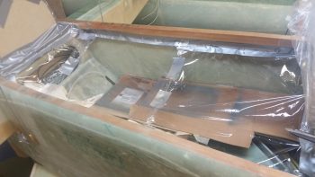
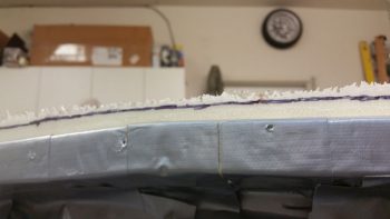
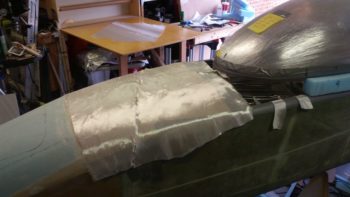
I started by pulling all the tape off that had done its job admirably in holding the thin plies of wood in place and in alignment atop the aft nose structure.

I then got to work cleaning it all up.  I pulled all the peel ply right away and then gave the exposed glass parts a good sanding.

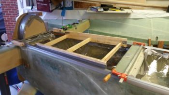
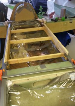
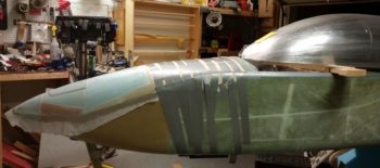
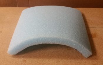
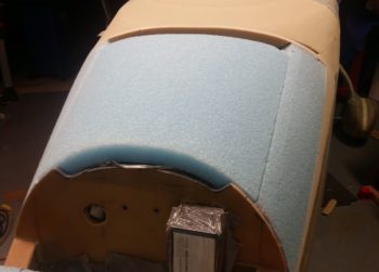
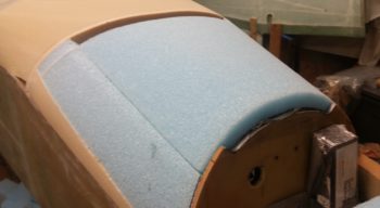
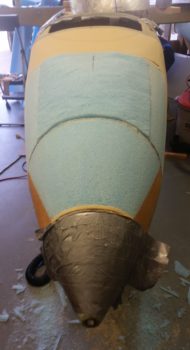
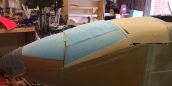
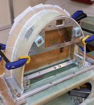
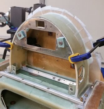
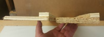
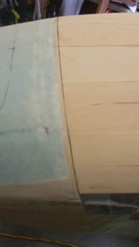
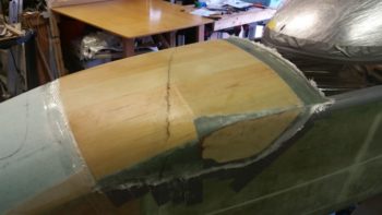
I then grabbed the long sanding board and went to work.  Since the aft nose cover was due to get 2 more plies of BID, as was the forward nose (1 ply for the entire nose, and 1 extra just for the nose hatch door… which I was going to extend aft) I then gave the intersection line –the now buried but visible intermediate bulkhead– a good working over to get the surfaces aligned with each other.

After a good 45 minutes of sanding and prepping, I was ready to start cutting some glass for the layup.  I had been thinking about my layup schedule while I was sanding, so I listed that out and my layup task list in fairly short order.

And then I hit the proverbial brick wall!!  Gasp! Ugh! Dammit! I was very, very close to being out of BID!  I knew I was getting close, but obviously didn’t realize I was THIS close to being out.  The implications on this was significant for today’s tasks specifically since if I had chosen to press forward with the canopy build, I don’t think I would have had enough… well, to do it all cleanly with singly pieces of BID per ply.

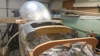
I did have enough for one ply to do the aft nose cover, so I simply changed my ply #2 from BID to UNI, so I could still get the cover glassed.  I was planning on peel plying the “final” layup anyway just because in an essentially on-the-fly design like the aft nose cover, there may be some unknown variables that crop up requiring extra glass to be laid up over the existing final glass skin.  Bottom line, if I need to layup more glass on the cover later on I’ll be poised to do so going the peel ply route.

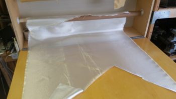
I then rummaged through my extensive spare UNI bin (who uses this stuff anyway?? … haha!) and quickly cobbled together a ply of UNI for the aft nose cover layup.  I chose to run the fibers across the nose to be perpendicular to the grain of the integral Basswood strips that make up the core of the cover.

Then I figured I would just forego the glass and simply varnish the wood… looks nice!   Maybe a bit of stain?!  HA! I jest…

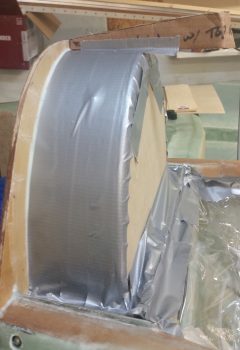
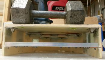
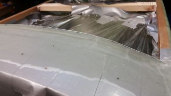
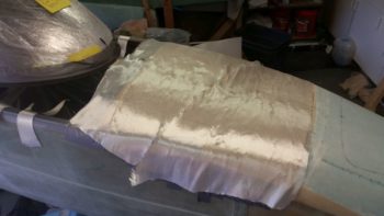
I then undertook what turned out to be quite a considerably in-depth layup (don’t they all! … we Long-EZ builders are suckers!  We always think things are going to get easier… or not take that long! heh)

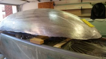
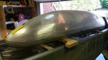
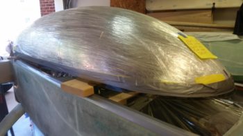
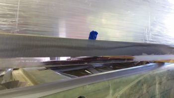
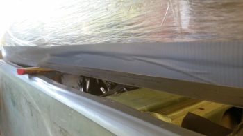
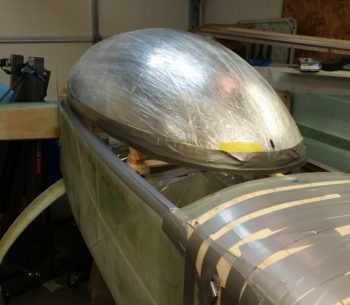
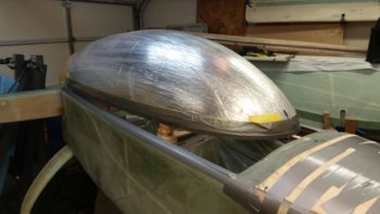
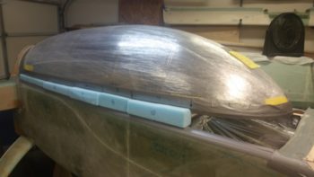
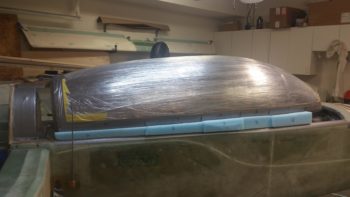
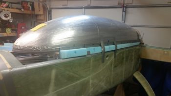
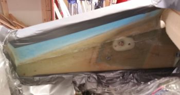
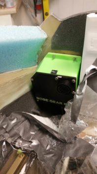
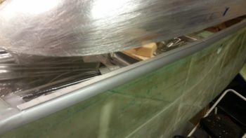
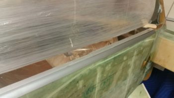
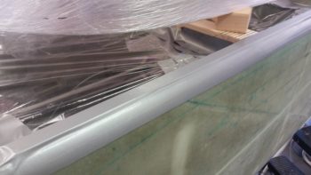
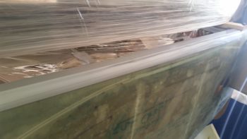
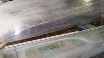
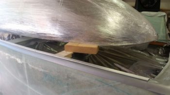
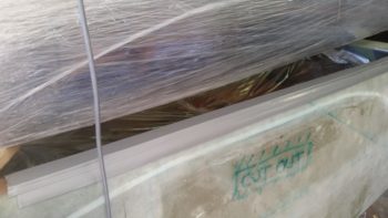
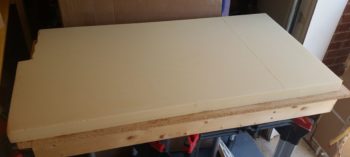
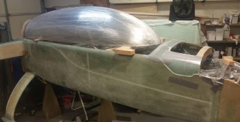
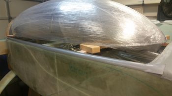
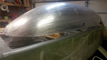
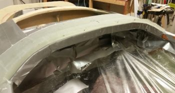
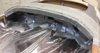
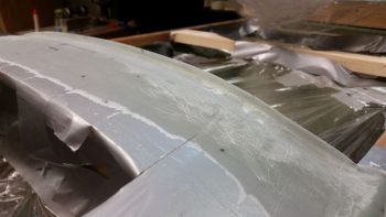
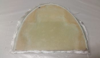
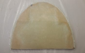
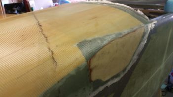
So many, many hours later I was glad to put the lid on this baby  . . . oh, yeah, forgot the peel ply.

So many, many hours later I was glad to put the lid on this baby  . . . with peel ply!

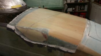
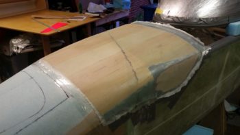
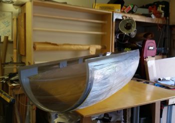
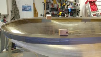
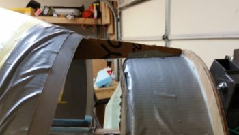
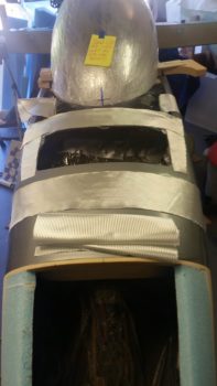
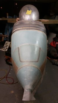
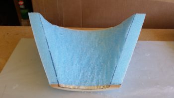
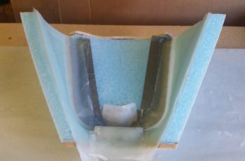
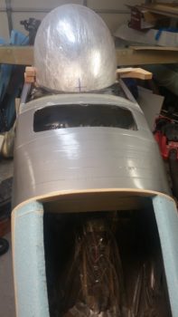
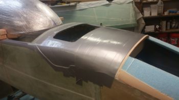
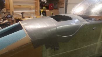
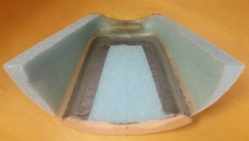
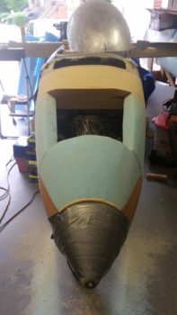
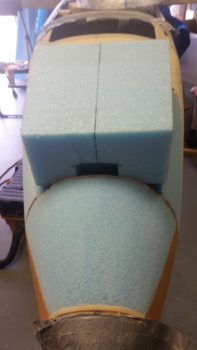
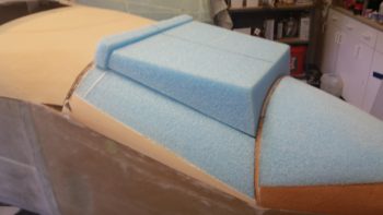
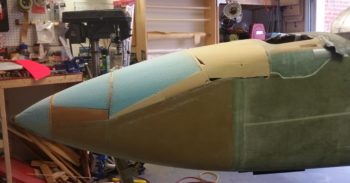
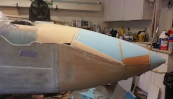
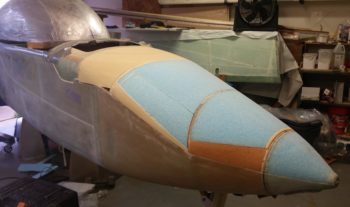
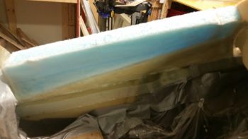
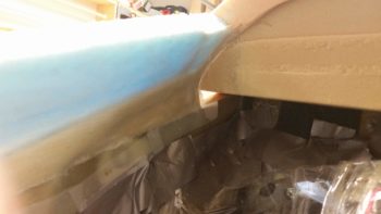
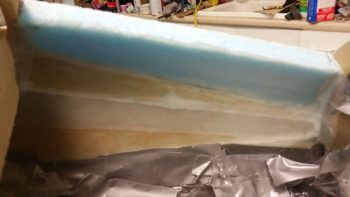
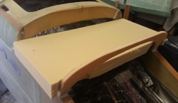
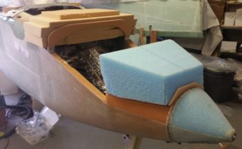
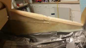
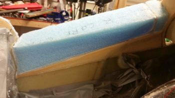
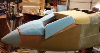
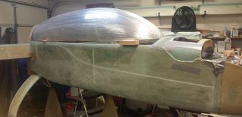
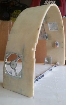
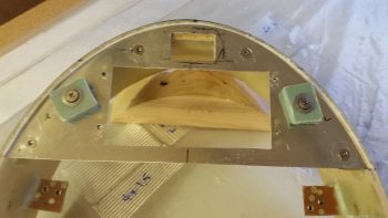
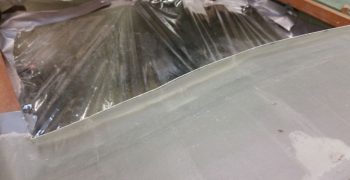
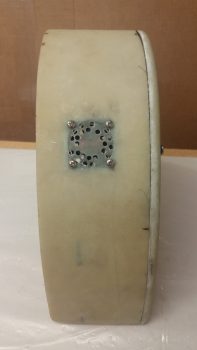
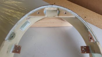
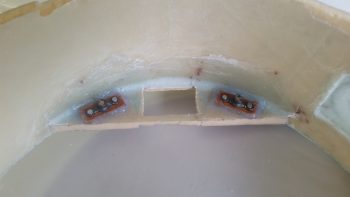
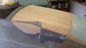
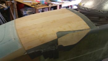
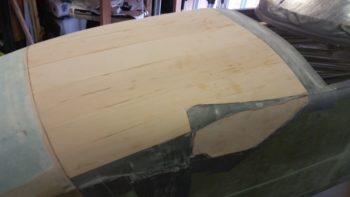
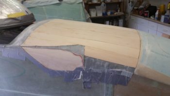
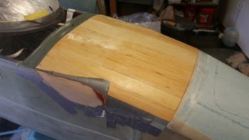
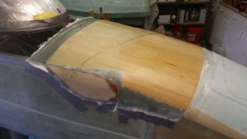
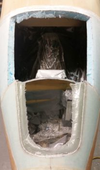
Backing up pre-peel ply, I would like to point out that to streamline the contour of the aft nose cover to the maximum extent possible, it meant incorporating the “pointiest” part of the entire nose structure –besides the very front– which is still those pesky F28/front longeron ends that I trimmed down as much as I felt I possibly could!

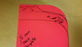
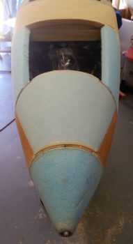
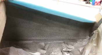
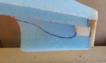
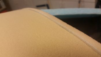
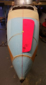
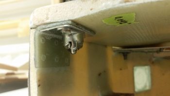
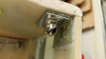
You may have wondered (or could care less!) about the triangular strip of glass with no wood over it, which is in fact the very front corner of the F28 bulkhead and where the longeron ends.  I’m kinda wishing I had taken it down at least another 1/8″, if not 3/16″ on each side.  Still, I think these abrupt shifts in the nose contours are common to Long-EZ’s since you’re taking basically a square box and turning it into a long conical nose.  So, don’t mistake my woulda, shoulda, coulda for displeasure, because I’m more than happy with this nose . . . yep, hind sight is always 20/20 on these builds!

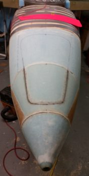
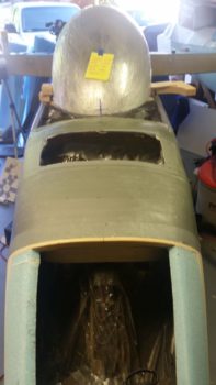
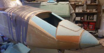
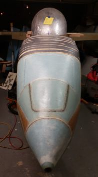
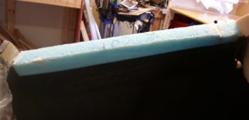
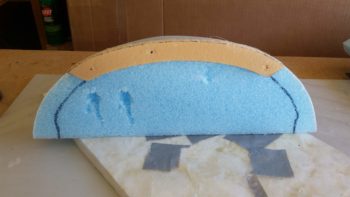
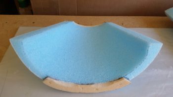
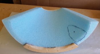
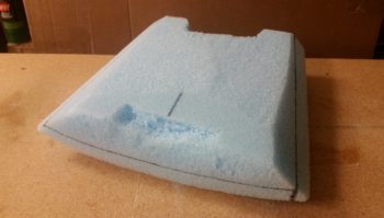
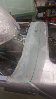
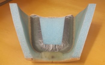
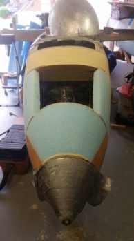
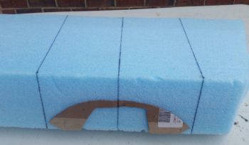
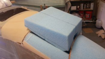
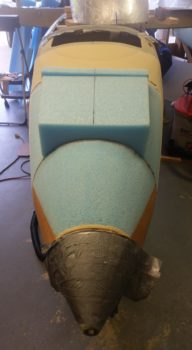
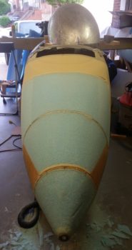
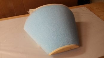
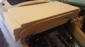
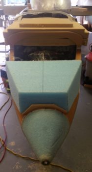
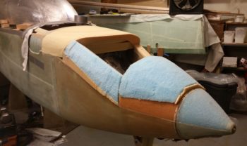
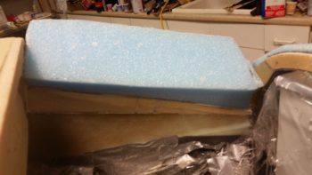
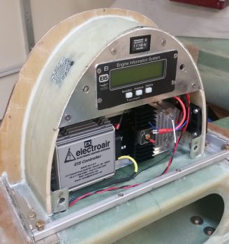
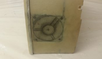
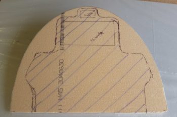
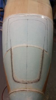
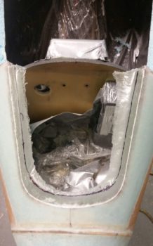
Another front view, this time showing the foam plug around the back half nose hatch marked up.

Before it got too late to make noise, I grabbed my Fein Saw and cut the perimeter of the front nose hatch door –NOT TOO DEEP!!– and then all the way through on the back half foam plug.

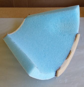
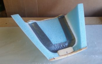
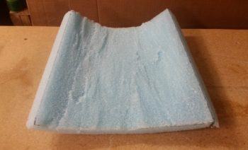
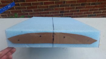
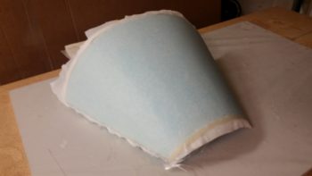
I then carefully removed the nose hatch door with the associated & attached foam plug on the back half of this odd piece.  Hmm, this does resemble something? … Oh, yeah, a fingernail!  . . .  just like I predicted!

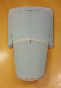
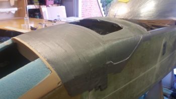
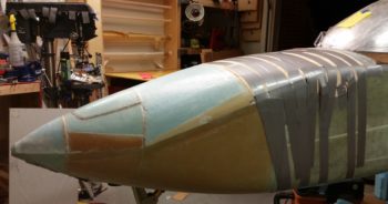
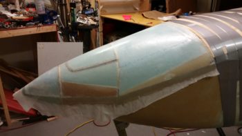
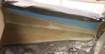
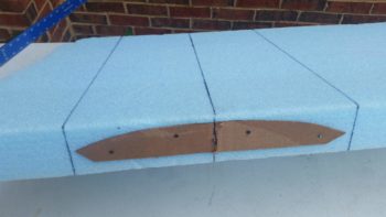
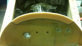
Here we have the underside of the nose hatch door.  I will essentially create the edge of the back half of the nose hatch as I did the front half.

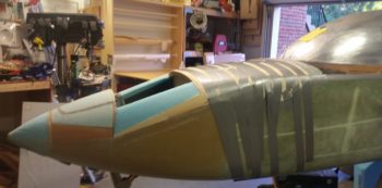
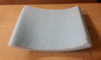
I then removed the duct tape from the underside edge of the nose front hatch door.  I have to say I’m really happy with how my single larger nose hatch door plan turned out!

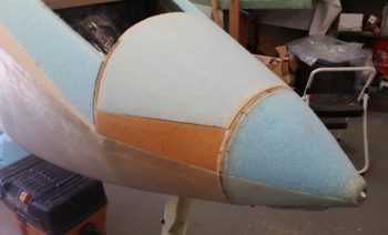
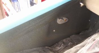
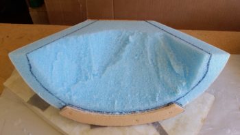
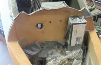
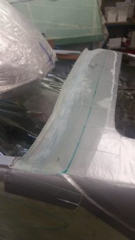
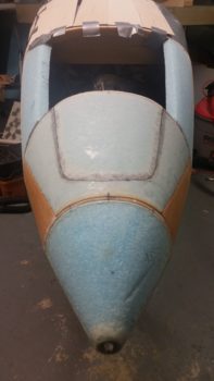
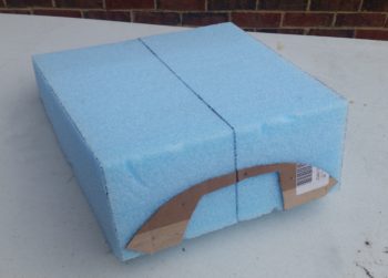
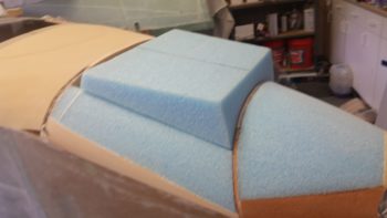
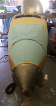
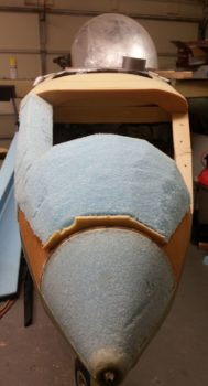
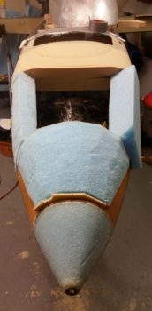
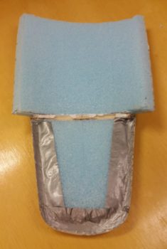
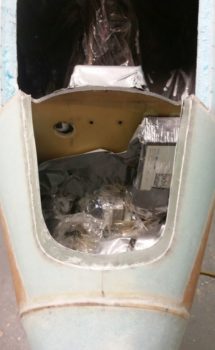
And here is the nose hatch in its current state… with the outline of the foam plug on the aft end visible.

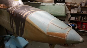
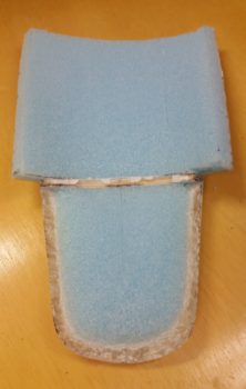
I then marked the cut line on the perimeter of the forward nose hatch flange to trim it down to a narrower, workable width.

Again, I grabbed my Fein saw and within a few minutes had a nice trimmed flange for the front half of the nose hatch door.

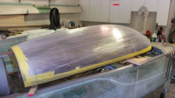
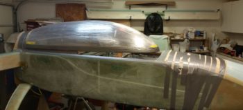
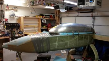
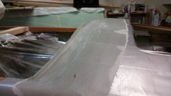
The aft nose/avionics top deck cover final layup really did take up about 5 hours total from start to finish.  Not to sound like a baby, but today was the hottest day of the year so far… so it was a bit toasty in the garage.  My son had called for Father’s Day, so I knocked off a few hours earlier than I normally would, grabbed a shower, a cold one and some dinner and had a good chat with my kid!

Tomorrow I will do a bit on the build, but I’ll have my eye on what will get loaded up for the move as well.  Tuesday will be full on packing so no build until I get back…  I know I said I wasn’t going to build after I get back from this trip, but due to my SNAFU with BID stock on hand, I will get the canopy done upon returning so that it is at least glassed externally… since I can’t/won’t transport the fuselage down to NC with micro’d-on pieces of foam clinging on for dear life!


Chapter 18 – It’s bittersweet . . .

I say bittersweet because my good friend Todd Silver, who I think just about every Canardian knew or knew of, had never actually installed a canopy on a Long-EZ even though he produced so many of them.  He made me promise that when I built my canopy that he could come help . . . well, this one’s for you Todd! (miss you buddy . . . )

I started out today cutting off the myriad of layers of protective plastic that was on the canopy to expose just the bottom and aft edges.

Once the edge was exposed, I used some . . . wha…? Yep, YELLOW painters tape. Supposedly the edge seals much better than the blue to guard against any epoxy wicking up the edges of the tape.  That was of course after I marked the appropriate width of the exposed canopy edge to be mounted into the canopy frame.

However, I suspected that just like the blue painters tape, the yellow probably doesn’t stand up to epoxy any better . . . so I covered the painters tape with duct tape for added security.

I then got to work sanding the edges of the canopy with 220 grit sandpaper, just as per plans.  I honestly planned on using the Dremel Tool like most other builders, but I literally happened upon a fresh piece of 220 grit sitting on my workbench.  Curiosity got the best of me and then I realized it really wasn’t that bad, so I just finished the entire canopy edge using the Ol Skool plans method.

You can see the sanded edge on each side in the pic below, whereas the middle section hadn’t been sanded yet.

Here we have the entire edge sanded with 220 grit sandpaper.

I also taped off and sanded a few key spots on the inside edge that would get hot glued to secure the canopy in place.  I also went ahead and taped and sanded the very aft inside edge because it gets micro’d directly to the foam back there… also so that if the micro decided to run at all, it would be on the tape vs bare canopy.

I then trimmed the front canopy positioning blocks to length (ok, the wrong length, but who’s counting!) and hot glued them in place on each side of the front canopy edge.

I then spent a little bit constructing the aft canopy spreader to keep the sides of the canopy splayed out into position, straight and at the proper elevation.  The canopy spreader sides are the wood pieces I glued up last week, with 0.4″ spacers along the top edge.  These spacers will drive the canopy further outboard so that they sit in the original position for a Long-EZ with standard width longerons…. remember, my longerons are 0.4″ wider from the pilot’s seat aft so this allows me to push the aft canopy sides out further and provides more of internal edge for aft canopy rail support.

I used ACS shipping dunnage cut to length for the internal spacers, and press fit everything together.  Then I hit all the joints with the hot glue gun.

A side shot of the canopy spreader assembly.  Now, I will note that I did have to adjust the front side of the entire assembly up about 1/4″ as I was setting the canopy in its final position on the fuselage.

I also added a 3/16″ spacer on each side on the very back to push the canopy –which really wanted to curl inward on the very aft edge– out just a hair.

Adding the 3/16″ spacer on each side as shown above also dropped the center aft top of the canopy right into perfect position so that it just barely kissed the extended cowling line angle template that I have taped to the top of the headrest.  I know the angle for the aft canopy edge and the turtleback is simply terrible, and it’s one of those things that I’m just going to have to bite the bullet on (and probably 2-3 knots!) since A) this is the only canopy I have, and B) it’s getting installed now!

The next bunch of pics all show the canopy set and hot glued into it’s final position on the fuselage.

I then started cutting out and shaping the blue foam blocks that run along the side of the canopy were it intersects the fuselage at the longerons.

A bit later I decided since it was late and that I was done cutting blue foam pieces, especially since the more intricate pieces at the front and very aft were next and I wanted to be a lot sharper than I was this late at night to undertake those beasts.  However, I didn’t want to call it a night without having something cooking in the proverbial oven!  So I whipped up some micro and set these babies in place… woo-hoo!

Here are the blue foam canopy rail pieces micro’d in place on the right side.

And here are the blue foam canopy rail pieces micro’d in place on the left side.  BTW, for fun I calculated the total edge length of the canopy and as I head off for the evening I know that I am literally 63% finished with the canopy frame… ha!

I’ll also report that I took a break from the canopy in the afternoon and pulled the peel ply off the nose and then cleaned it up.

Then just before turning out the lights in the shop, I did an initial markup of nose hatch just out of curiosity.  Here it is:

Tomorrow will be more canopy of course, and my goal is to get the external glass layups knocked out on the canopy frame by late tomorrow evening.  Get ‘er done!


Chapter 13 – Noseless no more!!!

That’s right folks, the nose is glassed!

At least the initial round…. with another round or two of glassing to follow.

I started off the day by taking a piece of paper and drawing a line down the center horizontally to create 2 panels.  On the top I drew out my front nose layup and all the associated tasks for completing that layup.  On the bottom I drew out the aft nose cover layup/construction and all the associated tasks for that endeavor.  Then, with it on a clip board downstairs I added a a few more points to watch out for and another few tasks as I was thinking about my upcoming layups as I cleaned and organized the shop.

Down in the shop, I started by laying out my thin Basswood and Birch plywood strips in an organized manner off to the side.

Like I mentioned above, I then spent about 30 minutes cleaning and organizing of the shop.  Wanna start fresh, right?!

With the glass cutting table cleared off I then cut all the BID required for the foundational underlayment for the wood strips above that will make up the aft nose/avionics top deck cover.  As a point of note, the glare shield structure will get another ply of fresh BID to tie it into the wood strips/cover structure that will get laid in over the fresh BID.

I then laid up all the glass on top of the protective duct tape barrier/mold releases I taped up last night.

Now, here I should have been a bit better on the uptake QA (Quality Assurance) wise and even noted my error in my blog last night when I was discussing getting the tape applied only 1 ply thick where I could.  My plan –that I did not follow for some reason– all along was to apply at least 3 plies of tape on the sides of the fuselage where I made the depressions.  So, I’m thinking the cover is going to fit a bit too snugly when I put it back in place once remove it… nothing that some sanding won’t remedy, but shows what lack of foresight and not following your own plan gets you: wasted time.  Still, better to be a bit too tight in this scenario than too loose!

Nonetheless, as hairy going as it went for a while (with me thinking ‘who’s crazy idea was this to put all these damn wood strips on here?!’) herding cats with all the wood strips going off in different directions, I finally wrangled them all into some semblance of order and strapped them down like nobody’s business!

A bit of irony is that I would have used the thick Gorilla duct tape (as I had mentally planned to do) on the sidewall depressions for added thickness on the mold release, but I ran out of it using the really long strips I needed for more holding (“clamping”) pressure of the tape to keep the considerable pressure I needed on the wood strips –especially at the corners– in place.  The 3M duct tape worked good for the 2 spots that I used it, but I’m thinking had it had to carry the entire load of keeping the wood structure in place, this would be an entirely different report altogether!

Here’s a shot of both the freshly re-glassed glare shield and the aft edge of all the wood strips, that when combined together collectively make up the cover-side raised break line interface with canopy skirt.

With the aft nose cover curing I then set my sights on the front half of the nose.  I spent some time assessing the nose hatch and the required components that would be mounted in, near and around it.  I realized that with the nose hatch latch installed, along with the hinge mounts for the aft nose/avionics top deck cover, that I just didn’t have enough nose real estate on the aft side of the hatch.  In short, the hatch was just too long and was eating up too much precious real estate on the inside of the nose in the area between the hatch and the aft cover.  I simply had to shorten the hatch length.

I spent another 10 minutes assessing the space required, and then ascertained that if I lop of 1.2″ off the aft end of the hatch that I could most likely squeeze all I needed to in the area between aft cover and front nose hatch.

I then got busy glassing the front side of the nose.

After the requisite sanding down the edges of the existing glass for smoother glass transition, and angling the sides of Napster just a hair, I then micro’d/floxed the battery compartment/front hatch structure into place.

It’s always a point of amusement, or at least interesting I guess, that the majority of the glassing process is applying the micro to the foam surface!  It’s amazing how long it takes compared to the actual process of putting the glass in place and wetting it out . . .

Nonetheless, rest assured micro was applied to all bare foam and then I laid up 1 ply of BID on the entire forward nose structure, overlapping onto the existing glass the requisite 1 inch.

I grabbed these shots from both the left and right sides of the front nose vs aft nose cover intersection.  This will be the one visible line that traverses across the nose other than the nose hatch door outline.

I then peel plied the entire forward nose layup.  Earlier I had considered laying up the 2 plies of BID prior to cutting out the nose hatch, but then decided against it since that would then require using only BID tapes to re-secure the aft nose hatch structure when I glass it back into the nose after creating the interior nose hatch perimeter on the underside/interior of the nose structure.  Nope, as much as I don’t like splitting up layups, the nose was getting only 1 ply of BID at this point…. so peel ply it is.

A couple more side shots of the peel plied forward nose layup.

And a wide angle shot showing the profile of the nose.  I really am loving the shape of this nose, and it’s incredible how long and narrow it looks without the canard installed to break it up.

As I let the glass cure on both the front and aft sides of the nose, tomorrow I will be focused solely on the canopy and will try to knock as much as that out as I can over the next couple of days.  Monday I go back into packing mode to prep for hauling another load of stuff (a BUNCH more airplane stuff this time around) down to NC.


Chapter 13 – Nosing around…

Better buckle up boys ‘n girls, this one’s gonna be a long one!

I started out by pulling the peel ply and trimming the glass edges on the nose battery compartment section cover.  I test fit it back in place and it still fits like a champ.

I then pulled the peel ply and trimmed the glass edges on the left and right interior nose sidewall extensions layups.  I cleaned up all the peel ply boogers and inspected the layups.

The layups themselves looked good and were of good quality, but I couldn’t get past the menagerie of varying colors, foam types, etc.  I simply did not want that staring me in the face every time I opened the nose hatch.  And I checked to see if these sides would be visible with the hatch open, and from what I could ascertain in my mental mockup it was a definite yes.

Since I already had a plastic cover in place to protect the nose components from all the nasties produced during the construction of the nose, I simply pulled the sides and move the tape line to just below the existing visible speckled paint I had shot before.  I then spent about 10-15 minutes adding a bit more protective barrier and tape, including the top side edges of the new foam sidewalls that I had just glassed.

I then hit the just-glassed interior nose sidewalls with a light coat of primer and a couple light coats of speckled paint.  Ahhh, HUGE improvement.  So, so, so much better!

I then remounted the pitch trim actuator bracket… if you compare this pic to the one above of the same sidewall…. wow, no contest.  I’m very glad I decided to take a half hour to remedy those eyesores!

I actually did a bunch of the following while the primer from my painting effort above dried, at which point I took a couple minutes to shoot the final speckled coats.

I measured the current sidewall widths both at the front and aft ends to then transcribe those sidewall widths onto the bottom of the nose battery compartment foam cover piece.

I then marked up the sidewall widths going up, as you can see on the aft side of the foam base of the cover here.

I then started dishing out the extra foam on the bottom side of the nose battery compartment cover.  As a point of note and as I explained a couple of blogs ago, this step would normally be done AFTER the entire nose had been glassed and the builder was shaping the internal side/top wall of the nose to then create the edges in regards to the hatch.  Again, due to the bulkhead in the middle (Napster) I’m doing all this before I glass the entire nose.

I then got to the final rough stage of foam removal on the nose battery compartment cover.

And then did a final sanding to smooth out the interior walls/top.

I then put the IBBS in its mounted position to check for not only clearance with the interior nose battery compartment cover walls, but enough space to mount and unmount the IBBS unit.

The black dot is where I marked a slight indentation from the corner of the IBBS pressing into the nose battery compartment cover interior foam surface.  I then marked an area around the contact point to give the IBBS a bit more room for ingress/egress if required.

I then carved/sanded the clearance required for the IBBS unit.

I then marked up the forward dimensions of the nose hatch door onto both the exterior (glass) and interior (foam) surfaces of the nose battery compartment cover.  I realize the nose hatch outline looks a bit off center in the pic below, but it must be an illusion created by the camera angle, because I rechecked all the dimensions from centerline and it’s both asymmetric overall and equidistant from the centerline.

I also carved out a small notch at the very front of the nose battery compartment cover to then insert a small piece of H250 high density foam.  Since I’ll have only one larger nose hatch that is attached via hinges at the front end and by one latch at the aft end, I want to ensure the front side is very securely fastened and the darn thing doesn’t blow off the aircraft, thus the high density foam plug insert at the front edge for added strength. It may be a bit of overkill, but I’d rather not wonder about the security of my nose hatch door!

I then had to angle the bottom edge of the H250 high density hinge attach hard point so that it was pretty much level and parallel with the waterline of the aircraft.

Since I carved away the nose hatch marking on the foam, I wanted to check exactly where the nose hatch edge line was, so I took the piece outside to check it out in the sun.  I could actually see the line in the shop, but thought this was a cool pic once I took it.

I then carved both the nose hatch door foam and the adjacent nose battery compartment cover interior foam down to create a gradual slope to where a lip will be created for the nose hatch door.  Now, I’m not really concerned about the actual nose hatch door foam here, since it will get its final shaping done when connected to the aft 2/3rds of the nose hatch door which will be positioned aft of the Napster bulkhead.

My main concern here was the nose battery compartment cover interior foam, both the transition of the foam and the width, position and quality of the glass along the foam edge. I had meant not to micro the foam when laying up the 1 ply of UNI on the external side of the foam, but didn’t remember until immediately after I had slathered on all the micro.

Thus, with a really rough surface to contend with, I took the piece out back and spent 15 minutes with the Dremel Tool carefully knocking off all the micro crud from the glass.  I then sanded it smooth with a Perma-A-Grit tool and called the glass surface acceptable for a glass-to-glass bond.

Since there is not a lot of sidewall here on each side of the nose hatch door opening, I opted to add another ply of BID to each side for added strength.  It’s not like there’s that much real estate to really make a huge impact on weight, and I figure this is also somewhat of a structural area simply in regards to the nose structure as a whole, and specifically for the constant swinging action of opening and closing a rather large nose hatch door.  I also added a couple of rectangular plies just over the H250 high density foam hinge mounting hard point.

The methodology that I’m employing here is that I am simply creating the lip of the nose hatch door now vs later.  The 3-ply nose battery compartment cover sidewall glass simply crosses and is glassed to the narrow bare glass threshold to then overlap onto the taped foam surface of the nose hatch door.  To be clear, the line for the nose hatch door goes pretty much down the center of this bare glass threshold.

The KEY to ALL of this is that when I cut the line for the forward side of the nose hatch door, I must be very careful and cut just through the top glass and not all the way through… which would negate all the work here and I would simply lop off the lip I have just created.  As insurance I added another ply of BID around 1/2″ wide to just below the nose hatch door outline.

I then of course peel plied the edges of the layup.

While the internal nose battery compartment cover layup cured, I then got to work on the what will be the back “half” of the nose hatch.  I will work this side of the nose hatch in a more traditional manner in that I will remove a piece of the nose with a few added inches around the marked nose hatch line, create the edge of the nose hatch hole & door, glass the piece, then return it to the nose for final glassing.

To do what I just described I’m essentially just removing the big center foam nose plug I created yesterday.  Yes, I know it’s better for bonding to glass multiple plies of glass all in one go, but here I don’t really have a choice (as I see it) if I want to make this single larger nose hatch a reality.  Thus, I won’t even micro in the big center foam nose plug when I lay up the initial single ply of BID on the nose.  I will simply mark the edges with a Sharpie to make it visible and then cut it out once the glass has cured.  When I do cut out this big center foam nose plug, I will also CAREFULLY cut out the then attached forward nose hatch door piece from the nose battery compartment cover.  It will probably look like a big blob of glassed foam with a giant fingernail sticking out!

To set myself up to make all this as easy as possibly, I wanted to dial in the general shape of the interior of the big center foam nose plug.  I determined the widths of the adjoining sidewalls and marked them up on the foam plug.

I then removed all the extra foam and rough shaped the underside of the big center foam nose plug.

And then hit it with a round sanding block to get a smooth surface on the underside, which besides the required depressions for the edge of the nose hatch, completes the major foam shaping –both internal and external— for the nose!

Here’s a view of the big center foam nose plug right side up.

I then of course test fitted the freshly carved (underside) of the big center foam nose plug. Looks like it will work (fingers crossed!) . . .

With the front half of the nose pretty much squared away and nearing completion… after the internal nose battery compartment cover layup cured, I then set my sights on the aft side of the nose: the cover.

The first order of business was to sand a depression on the entire front side of the urethane foam plug that abuts the aft side of the intermediate bulkhead.  This depression –or elevation adjustment– is required to help match up the nose glass level between the aft side cover and the front side nose glass.  Since a layer of tape, then a couple plies of BID followed by strips of 1/16″ thick Basswood will be employed to create the base of the aft nose cover, I transitioned the urethane foam plug to be a bit deeper than a narrow mixing popsicle stick (~ 0.080″).

Here you can see the depression below the edge of the intermediate bulkhead.

After some more pondering, thinking and assessing, I then made the command decision to move the break line between the forward canopy opening and the nose to intersect with the angled edge of the aft nose cover right at the sides where the angle ends and transitions into a small length that traverses aft to intersect with the outboard ends of the glare shield… this segment is just along the top of the longeron for a few inches.  This will allow the canopy skirt to cover up (hide) the cover segment along the longerons and will give the appearance of a converging 3-line intersection: ONE single line along the longeron, the canopy break line across the top of the nose, and the angled aft-up-sloped cover line.  Think of a sideways “Y” for visualizing it a bit better.

I had originally envisioned the front break line of my canopy to be a bit more curvy and sexy, but decided to make it a bit straighter across the front with some curve at the outboard edges.  I think this will be cleaner and simpler, allowing the lines to flow better visually, especially when the canopy is open since the canopy break line will parallel the glares shield lines.  It also makes constructing the cover and canopy skirt considerably easier since I don’t have to carve/match a more detailed curve for the break line.

I then finished duct taping the aft nose for the eventual cover glassing.  Rest assured, since I went through great lengths to minimize the depth and thickness of the tape (read: 1 ply) this took a fair bit of time and effort.

I also cut some glass away from the outboard edge of the glare shield layup to reglass it with the aft edge of the lower angled cover depression dialed in this time around.  Here’s some side views of the taped up aft nose ready for some glass to create the aft nose cover.

To bridge the obvious Grand Canyon sized hole I have in the top of my aft nose area, after weeks (actually years) of thinking I decided to go with thin, fairly flexible 4″ wide strips of Basswood… which is very close to Balsa wood in characteristics, just a tad denser and a little less fragile.  It is still very lightweight nonetheless.

Here’s a quick shot of the Basswood measured to length and shaped to be mounted to the aft nose surface to create the cover.  I know it looks a bit in rough, raw form, but when secured in place they will flow together and create a much more uniform shape than shown here.  Also, I didn’t get a close up shot of it here, and it may not be readily apparent, but the aft edge of the combined Basswood strips make up the raised edge on the cover side for the break line with the canopy skirt.

The more detailed piece of wood that makes up the cover’s edge inside the sidewall depression (shown above) is a slightly thinner piece of 1/32″ Birch plywood.

It was very late so I did one final push for the evening to finalize the preparations for both the front and aft side nose sections for glass.  By this point the internal nose battery compartment cover layup had cured.  Not 100% (thankfully!) and was still just pliable enough for me to razor trim the edges with a knife.  I also pulled the peel ply and cleaned up the edges and all the peel ply boogers.

The layup looked really good and looks like it will work according to plan.  Here’s an internal shot of how it will look from the aft side once it’s installed in place.

I then of course had to test fit it back in its place on the nose.

Looking pretty good!

With that, both the forward and aft nose sections are ready for their initial rounds of layups. It’s really late… so I am calling it a night!


Chapter 13 – Nose shape complete!

I started out today by initially sanding down the shape of the nose in pic #1 on the left, then did round 2 as shown in the pic on the right.  As you can probably tell I spent a fair bit of time sanding on the intermediate bulkhead’s “shoulders.”

After some quick thought I decided that to fill in the gaping hole in the middle of the nose I would use one big plug.  Yes, I would account for the differences in the forward and aft angles, but I would start with 1 big foam plug.

I grabbed a good candidate piece of blue foam and marked a centerline on it.

I had just made up a cardboard template for both the front and aft sides of the hole I was attempting to fill.  I then pinned the templates in place to the foam plug with nails.

I then cut the sides of my foam plug which gave me a big block of blue foam to start my adventures with!

I then did a test fit and realized that this might take a while.  Plus I was thinking, “Do I really want to go this route . . . eh, what the heck, let’s give ‘er a try!”

A side shot after a bit more finagling and a lot of cutting and sanding.

Looking a little bit better . . . at least it’s not so proud.

Ahhh, now we’re getting somewhere!

Now, as I mentioned yesterday, with these angles there needs to be some relief somewhere, so I had about a 1.5″ strip on the back side that I would then simply fill in with another strip of foam.

Which is exactly what I did!

Here you can see the main plug and the smaller gap filler piece in the back.

With all the dimensions, angles and fit looking pretty good on my foam filler plug pieces, I then set them in place and started hacking away with a wood saw.

Here’s the final result of my Neanderthal shenanigans with the wood saw.

I then got serious and used the long board to get a final shape of my nose! hoo-ah!

Here’s a couple profile pics of my new nose job!

And a more formal pic after I cleaned up the shop and straightened the canopy (ahem!) up.

And a quarter angle shot.  You might notice where it tends to flatten out just a hair around the Napster bulkhead.  Minor variances like this will of course be mitigated during the surface micro finishing process.

I then grabbed a line to quickly lay out the nose center line.

And then set the nose hatch template half in place.  I think this will be a great size and shape for the nose hatch.

And AFTER I set it in the position I wanted from front to back, I checked the notch on Napster to see if I had determined it correctly (remember, it’s a bit tricky since the bulkhead is curved!)…. but I was well within 0.1″ on each side.  Not bad!

After I spent a little bit of time sanding the surface of the battery compartment foam nose piece just a bit to ensure a ply of UNI would bring it back up to level with the rest of the nose, I then removed it from the nose and vacuumed it for a layup.

I then micro slurried the foam and laid up 1 ply of UNI with the threads going from side to side.  I then peel plied the layup.

I laid up a ply of glass on this piece because I will actually carve it out and glass the interior sidewalls before mounting it onto the nose for good.  Then when I create the nose hatch I can just lay up BID tapes on the inside to secure this foam piece in place as far as internal layups are concerned.

I then spent a little bit of time sanding the interior of the nose sidewalls that I micro’d into place.  Once they were to my liking, I then vacuumed out the interior of the nose and the foam in prep for glass.  I also test fitted the RCU (Nose gear Relay Control Unit) –in the box that Marco 3D printed for me– to ensure that it fit with the new sidewall in place.  As you can see, it fit with room to spare.  I guess I did ok on the box dimensions! (grin)

I then laid up 2 plies of BID on the right nose sidewall’s new foam, overlapping about an inch onto the existing sidewall glass on the bottom, and the same in the front corner where the glass overlapped onto the aft side of Napster.

I then peel plied a 2″ strip along the top, the front and aft edges, and an inch wide along the bottom.

I then reloaded and repeated the same process for the left side new nose sidewall foam. Both layups turned out pretty good even though the foam underneath wasn’t perfect.

Of course I’ll continue my nose building quest tomorrow.


Chapter 13/18/22 – Napster’s Rug

First off, before I begin my tales of wonder on the canopy and nose builds, I figured I would finally get around to showing you this…. over on the left side the pic, attached the front of the box that is the Trig TT22 Mode S Transponder is the GRT serial adapter which allows the GRT HXr EFIS control the remotely mounted transponder.

In the shop, I started back on getting the longerons prepped for the canopy frame build. On the left side I started by inserting a 1/8″ aluminum thick spacer atop the longeron, the length of what will be the entire canopy frame.  As a reminder, this will allow me to do 2 things: 1) Place a 1/16″ hardpoint both front & aft on the longeron, then also a matching 1/16″ thick hardpoint both front & aft on the canopy frame, which will serve to maintain a 1/8″ gap between canopy frame and longeron.  2)  Inside the constant 1/8″ gap I will lay in a “Double-D” seal that is 0.2″ thick.  Proper compression is around 30%, so compressing it down to 1/8″ should allow for a proper seal of the canopy without crushing or mangling the seal over the years.

Based on my buddy Dave Berenholtz’ report during his canopy build that the 0.048″ thick glass on the BOTTOM of the canopy frame rails is not accounted for in the plans, with the builder being left to fend for himself, I used extra thick Gorilla duct tape for both tape runs here (above and below the spacer) to help account for that glass thickness.

I originally wasn’t going to put any spacer on the right side since it gets hinges… right? Well, as I was pondering the new mondo massive hinges I was putting in place I realized I had to account for the added height of these new, much larger hinges.  They do in fact measure roughly twice the thickness as the original plans hinges (a bit over 1/4″ vs a bit over 1/8″).  Since my canopy frame will not have as much surface area as the plans version, and will have narrower frame side rails, my revised plan is to simply leave the hinge depression on the bottom of the right canopy frame rail the same depth as per plans (0.150″).

The stock plans depression pretty much swallows up the entire closed stock hinge (both halves) whereas on my version it will only eat up half the hinge, with the other half exposed.  Since half of my new, larger hinge is roughly 1/8″ thick, I decided to then also add a 1/8″ longeron spacer and configure everything on the right side canopy frame to be better optimized for using the seal over on that side as well.  I will most likely incorporate the front and aft hard points as well.

The only issue with my modified plan was that I only picked up enough 1/8″ thick aluminum stock to add a spacer to the left longeron.  While I did have a considerable amount left over to use on the right side, I ended up having to rip a piece of scrap wood down to 1/8″ thick x 1″ wide for the aft end of the longeron (remember, from my pilot’s seat aft my longerons are 0.3-0.4″ wider than stock … 1.1″ total width).

As I did on the left, I then taped the spacer in place with extra thick Gorilla duct tape.

I then left the canopy alone until after I get the nose glassed.  Since the front height of the canopy frame will take its queue from the glare shield/drip guard since they intersect, I will pretty much finish the major glassing on the nose and avionics top deck cover before I finish the canopy.  Yes, I was originally thinking I would do all at the same time, but I really have to do it sequentially now since the intersection of the front canopy frame and aft side of the nose cover is a bit intricate.

My first task was to get the area between F28 and F22 –where the canard sits– filled in with urethane foam that will act as a plug merely to be shaped, taped up and then glassed over to make up the aft nose/avionics top deck cover.  I measured the first piece and cut it out of the big pieces of urethane foam I bought at the very beginning of the project not knowing that I would never use it on the actual aircraft.

I then set it in place and secured it with a couple long sheetrock screws.

And then continued to fill in the gaping hole atop my nose section.

And finally got the canard mounting area hole, between F28 and F22, filled in.

As you can see, I also found a perfect candidate block of big blue foam to fill in the front top part of the battery compartment, which sits immediately forward of the Napster bulkhead.

Here’s a front view of 2 of the 3 nose sections filled in with foam…. obviously needing some shaping to be sure.

I then hit a decision point.  Which at the time I didn’t specifically identify as a decision point, it just happened rather organically.  I had a related twofold issue at hand, the latter associated with my overall nose issue, which I’ll address shortly.

The first issue with adding foam to the area between the Napster bulkhead and the intermediate bulkhead was actually rather self-induced, in that simply the angles on each end are acute (less than 90°) and so I simply couldn’t just drop a block of foam in from the top. I did realize that this would be an issue when I glassed in the intermediate bulkhead, but I still felt the positioning of the intermediate bulkhead and its configuration was the best option when I did it… and still do.

My solution was rather a simple one, fill in the corner between the intermediate bulkhead and the existing nose sidewall so that the angle on aft end of the last open (non-foamed) nose compartment was more than 90° (obtuse angle to be specific).  Not that hard, so that was the plan.

However, as I collected up my leftover scraps of 2″ thick PVC foam from the original nose construction, I was thinking A) how best to utilize these scraps (underlying tenet here: I’m cheap!) and, B) how do I best configure the foam to ensure clearance for the pitch trim actuator bracket.

Ok, stay with me…. haha!

All this pondering led me back to the original overarching issue that I have with glassing the nose, which is part 2 of my twofold issue from above: constructing the nose hatch. You see, my Davenport nose design does not lend itself well to having just one nose hatch, but two.  Why?  Well, it’s all due to that devious little basterd, Napster!  Having a bulkhead right in the middle of your hatch makes constructing one (at least for me) a bit problematic.

I say this because normally hatches in the nose (on Long-EZ’s anyway) are made by simply filling in the nose with foam, shaping the foam, glassing the resulting nose shape, marking up the hatch on the new glass, then cutting it all off! Then with the removed nose shaped block of foam you whittle away the inside foam till it looks like a contoured nose inside…. then cut out the hatch, glass the lip in place and the rest of the interior nose foam, and then using the new nose hatch hole glass the nose structure back on with BID tapes on the inside between existing nose and new interior nose structure.  Ah, not too difficult, eh? Until a bulkhead is placed in the middle of all that!

So, to end the bleeding on this segment of my blog, I will just state that I resorted to my normal course of action regarding airplane building at this juncture: I decided to simply build from the inside out.  It will most likely add a day or two to my nose build, but I will get what I have identified as my requirement: a single larger nose hatch.

Thus, instead of changing the angles between the intermediate bulkhead and Napster, I simply started building the sidewalls.  My idea is to finish the INTERIOR nose just up the point surrounding the hatch, and then carefully work it in conjunction with the battery compartment side of the hatch.

I then shaped a long wedge piece of PVC foam to add onto the right nose wall.

And micro’d it in place, securing it with nails (and one screw).

Not having one solid matching piece to do the same on the left side, I cobbled some pieces of 2″ thick PVC foam together to then make close to the same structure as on the right.  I then micro’d these pieces in place.

With the multitude of angles at play on these nose pieces, trying to fit one in place is both maddening and time consuming.  One has to simply accept the fact that rarely will you get a solid block in there at one go, and at least one other piece will have to be added… either at the front or back.  And often two pieces will be required: one front and one back. I was able to get a decent sized chunk of blue foam in place on the right side with ONLY one required added piece to fill in the gap on the back side.

I thought I had taken a previous shot of this foam piece before I rough shaped the nose foam bits, but apparently not.

Another shot of the foam on the nose, roughly shaped.  The foam piece I added in the middle section on the right (left in pic) looks thick, but a good majority of that will be sanded away when I do the final nose contouring.

To alleviate some of the problem that I detailed above in creating one large nose hatch vs multiple hatches with a bulkhead in the middle, is exactly why Napster came into being in the first place.  When I constructed the nose pieces back in 2013, I determined the width of my hatch and notched the top of the Napster bulkhead (I don’t even remember the actual nomenclature of this bulkhead!) to allow for the thickness of the hatch door.

Here I’ve created what is going to be a transition point from the forward battery compartment to the NG30 compartment using a piece of 3/8″ thick PVC foam.  It’s Napster’s toupee if you will, and it will serve essentially as an embedded bulkhead in the structure of the nose hatch door.  Before I cut this foam out, I taped up the indention on the top of the Bulkhead (Napster’s head) with 3 plies of thick Gorilla duct tape to build in clearance between the nose hatch door and the Napster bulkhead.  This duct tape will also serve as a release agent when it comes time to remove the hatch door (remember, I won’t be pulling the entire nose structure off like is traditionally done in building nose hatches since I’m scratch building the nose hatch in situ.

In line with what I said above, here you can see that the interior edge of the foam that I’ve micro’d in thus far is contoured close to its final shape as it will be to make up the interior nose wall.  After one more piece is added to the right side, I’ll do a final shaping of the interior foam and actually glass it with a ply of BID.

Here’s a closer shot.  At this point the walls are 1″ thick, and they’ll most likely narrow to about 0.8″ thick towards the nose top.

My final push for the evening was to mirror the right side and get a decent sized chunk of blue foam micro’d in place on the left side of the nose.  It turned out fairly well, although due to the angles when it was finally micro’d in place I realized that for all surfaces to be as close as possible in maximum strength and to minimize micro usage, that the thickness of the wall is about 1.35″ thick… so more sanding down of the interior wall will be required before final glassing (it would have anyway, but this will be a bit more aggressive sanding to start).

It was late so I didn’t trim down the exterior of the newly added piece of foam… even more so because the micro hadn’t cured yet.  So after almost an hour of cleaning up the massive amounts of foam and dust in the shop, I called it a night.

Here’s a parting shot for the evening of the nose under construction.  It will be fun to look back at the nose in its current hodge-podge state, all cobbled together, to what it will eventually end up looking like!

Again, tomorrow will be all nose focused until I get it knocked out, then I’ll transition into the canopy build.


Chapter 18 – Initial canopy prep

Today I started out by pulling the peel ply and cleaning up the layups securing the GIB headrest to the fuselage, specifically to the front side of the firewall and sitting atop the CS Spar.  Rest assured this was no quick effort, and took well over an hour to complete.

I then attached the headrest cover in place with the lower 2 CAMLOCs (Late last night I figured out the stud lengths I need to acquire for the top set) and was quite pleased at the fit and finish of the cover.

As I was trimming the internal headrest layups, I mounted stuff to make sure it all fit.  Here I test mounted the cooling fan after removing a decent sized piece of glass overhanging the bottom edge of the fan notch in the sidewall.  I also took the opportunity to test out the length of the new SS CS mounting screws I picked up for its installation.

With both fans installed, I also took the opportunity to reallocate some wire from the smaller exhaust cooling fan to the larger intake cooling fan to allow the latter’s wires to reach the right-side mounted fan controller.

I then spent a bit of time doing some final assessments and measuring before I pulled the trigger and drilled the firewall pass-thrus in the lower outboard corners of the GIB headrest.

I had some errands to run and a few personal things to get done, so while I was out I picked up some more hardware for the headrest components.  When I returned I installed just about everything in the headrest for the first time all together.

I then test fitted the front cover with ALL the components inside… still fit like a champ!

I wasn’t able to fit the set of the fuel probe control heads into the GIB headrest structure… yet.  Simply due to lack of space.

However, looking inside the fuel probe control boxes I noted that the control board is fairly small compared to the actual box its mounted inside.  I’m thinking I may remount the control board in a smaller form factor that would allow these units to be mounted inside the GIB headrest…. since it really would make for easier wiring, integration, etc.

Since the GIB headrest is pretty much finished I had to say goodbye to some old friends that have been hanging around since 2012.  I made these guys up to check fitting and configuration on the GIB headrest internals long before I really had anything other than the basic airframe components on hand.  These guys sure have been useful over the years, but I certainly don’t have a need for them anymore since the real versions are on hand and installed in the fuselage!

I then taped up the GIB headrest and immediate surrounding area in prep for canopy installation/construction/glassing.

As I did on the front fuselage side, I also covered up the back seat area with clear plastic to minimize any canopy build nasties getting on anything.

I then noted that I forgot all about the top cowling angle template that I had made up out of cardboard.  Now that the GIB headrest was in place I could no longer set the top cowling angle template in place.

I decided on a simple fix to remedy my oversight, and started by measuring the distance from the top of the headrest to the top edge of the firewall: 0.5″.

I then transferred that dimension over to the cardboard template and cut it at a right angle to match the top line of the GIB headrest which is 90° perpendicular to the firewall.  Voila! Now I have my top cowling angle denoted for the canopy build once again.

I then spent the next couple of hours just getting a feel for the canopy and how it sat free form on the top of the fuselage.  I took a myriad of measurements, checked height, checked width, checked length, and checked clearances forward and aft . . . all to get a good understanding of how the canopy would best fit onto the fuselage.  BTW, I included both pics below since they’re at different angles.

I then grabbed a quick shot from the front.

Then, after finalizing a few decisions, I did the initial taping of both the right and left longerons.

Tomorrow will be all canopy and nose from this point forward.  There is a ton of stuff to do to be sure to get both the nose and canopy constructed over next week, but I think I can get most if not all of ‘er done!


Chapter 18 – GIB headrest installed!

I actually started out today by putting the finishing touches on yesterday’s blog post.  I was quite tired after the long haul yesterday, too much so to finish my post.

I then ran up to the Dulles airport area to pick up some of my stuff from friends who have been using/storing it.

After grabbing some lunch and returning home, and unloading the goods, I then got busy on finishing up the final few tasks I needed to that would allow me to glass in the GIB headrest.

First up was cutting out opening in the left headrest sidewall for the cooling fan intake.  I also drilled the corner holes for the mounting screws as well.

I then test-fitted the cooling fan.

And then tried out a mocked up installation of the cooling fan inlet cover bracket.

I then snapped the inlet cover/filter element into place.  Looks like this will work just spiffy!

Here’s a rather artistic shot (ha!) of the 2 cooling fan mounts.

Another shot just showing the CAMLOC mounting through holes in the headrest top plate.

I then prepped and floxed in the upper CAMLOC brackets for securing the GIB headrest front cover.  As you can see by this pic, I had taken it a bit later after actually all the floxing as I had since cut out all the glass (BID) required to glass the headrest structure into the fuselage, on the front face of the firewall.

To flox in the upper CAMLOC brackets I had to use a scrap piece of glassed 3/8″ foam on each side to keep the bracket tight against the backside of the top plate.

As I was prepping to whip up some epoxy for glassing the headrest into the fuselage, a giant hornet flew into my shop and started buzzing around (I’m guessing that’s what it is, to be honest I don’t know the true taxonomy of this insect…)  I was willing to let his trespassing into my sacred shop go unchallenged, but he then entered into a fairly aggressive posture, forcing me to employ countermeasures!  I hit him with a few shots of Simple Green, wetting his wings down so he death spiraled to the floor…. the death part of that action coming from my shoe compressing his earthly form into the concrete underneath!  In short, I killed the obnoxious little bastard . . . (ok, actually quite huge!)

So over 2 hours later this is what popped out the other end of the night’s endeavor: one GIB headrest, floxed and glassed in place on top of the CS Spar and on the front side of the firewall!  (…. yay!)

Here’s a shot from the other side.  Obviously I can now put all my efforts into the nose and canopy builds.

With the GIB headrest installed, tomorrow will be all about final preps and the no kidding real official start of the nose and canopy builds!

Chapter 18 – Headrest Transition

I started out today by pulling my table saw out from the outdoor shed and cutting some wood in prep for the the canopy install.  The forecast was for afternoon thunderstorms, so I wanted to get the wood cutting out of the way, and I just made it before the rain started… by about 15 minutes.

One piece that I cut was the forward canopy cross support that will both support and align the forward end of the canopy during construction of the canopy frame.

The actual final bit of supporting and aligning is done with these 2 blocks.  The top, outboard edge of each block has a 1/8″ notch cut into it for the canopy bottom edge to nestle into for alignment.

For the aft side of the canopy, I created the side rails of what will be a spreader, each of which will push out against the longeron, and concurrently the bottom inside edge of the canopy to keep it splayed out in the right configuration during glassing.

Since my longerons are a bit wider from the pilot’s seat bulkhead aft, I glued on a 0.3″ strip of wood at the top of each spreader that will be the actual contact point against the inside of canopy edge to keep the canopy sides pushed outward.  This puts the canopy edge aligned with what would be the original inboard edge of the longeron, giving me (or the GIB really) about 5/8″ more canopy width internally and also creating a wider internal lip to allow for a bit wider canopy rail to interface with the longeron.

Here’s an end view of the canopy spreaders with the added 0.3″ strip at the top of each one.

I went back to my blog to refresh my memory to see how I installed the CAMLOCs when I put them in for the pilot’s seat thigh support.  In my own blog I mention not having the correct rivets on hand.  And I’ll be darned if I never ordered those correct rivets!! Argh!

The only 1/8″ rivets I have on hand that would work in general are button head rivets, and for installing the CAMLOC receptacle brackets for the headrest cover I definitely needed countersunk head rivets.  Since I have the much larger 5/32″ rivets on hand, which are fairly long as well just as a point of note, I decided to use them instead.

This of course meant drilling each lightweight STAINLESS STEEL CAMLOC receptacle (these are actually a SkyBolt product btw) to widen the rivet mounting holes from 1/8″ to 5/32″ diameter.  In the end it really wasn’t that difficult.  The only negative was that I set the 5/32″ drill bit down for a second conveniently located right next to the 11/64″ bit… which is what I of course grabbed to drill the wider rivet holes!  DOH!  Oh, well, a few thou more of play but they still worked fine.

Here you can see the differences in rivet size.  Of course I ended up cutting the length way down on the 5/32″ rivets.

After fiddling about with getting the cover in the best spot (there will be some trimming of the cover along the edges), I prepped the lower CAMLOC brackets and floxed them into place.

Here’s the right side lower CAMLOC bracket to secure the headrest cover into place.

And the left side.

I then got to work on the glare shield.  I started by pulling off the little foam wall I had built to create the raised drip (or “anti” drip I guess) edge.

I then marked the drip edge for trimming, at about 0.35″ high.

It’s hard to see in the pics above, but the raised drip edge still has some nasty gnarly edges from the original glassing.

I then used the Fein saw to cut the glare shield’s raised drip edge.

And a final couple of shots of the trimmed raised drip edge on the glare shield, after some very aggressive sanding to get the surface just forward of the drip edge to a nice smooth curve.  I think once the additional plies of glass are added this area will turn out very nice!

I then made up/prepped the 2 upper CAMLOC receptacle bracket assemblies only this time I used 1/16″ thick angled aluminum for the brackets.

Here we have the GIB headrest faceplate cover held in place with the 2 lower installed CAMLOC assemblies.

Here I’ve simply slid the top CAMLOC studs (which I will need to order longer ones for the top) in place for this pic.

I then spent a little bit of time drilling the vent holes for the upper cooling fan (exhaust).  I know the holes may look like I drilled them willy-nilly, but there is actually a pattern that follows the configuration of the fan to optimize airflow out of the headrest structure.

Since it was fairly late, I couldn’t fire up my Fein saw, so I’ll get to cutting out the sidewall glass for the lower intake cooling fan tomorrow.  I did mark it up in prep for that.

Clearly I didn’t get the headrest structure glassed into the fuselage yet, mainly because I wanted much easier access for working both the cooling fans and the CAMLOCs attachment assemblies.  I should get to glassing it in tomorrow and then pressing forward full bore on the nose and canopy build.


Chapter 18 – Yep, still on headrest

Today was pretty much a full day on the GIB headrest structure again.  However, I think that tomorrow I should honestly have everything wrapped up on the headrest –since I’m running out of tasks to do on it– and I will, no matter what, be getting on to the prep for the nose and canopy builds.

I started out by pulling the peel ply on the top plate reinforcement layups and trimming the glass.  I also pulled the upper exhaust cooling fan out of it’s recessed notch in the sidewall. It took a bit of convincing, but I finally got the little fella out of the glassed notch.

The same was true for the larger intake cooling fan, although it did come out a lot easier than the little fan.  I will say that the layups inside both the fan notches look good and will definitely do the job.

One task I did last night but failed to mention, probably because I didn’t have a pic of it, was creating flox hard points in the depressed foam sides for the Hobbs meter mounting screws.  Here you can see that the hard points are cured.  You can also see I lost a bit of foam off the front strip, which I will glue back into place.

I then test fitted the Hobbs meter, which fit snuggly but just fine.

I then made up 2 K1000-3 nutplate assemblies for the top plate upper mounting screws.

I then floxed the nutates in place and secured them with 2 spare AN3 bolts.

I then marked up the aft side of the foam headrest cover piece to depict what area(s) would get sanded down to create a depression in the foam.  The areas not sanded down or depressed are the portions that interface with the front edge of the headrest structure, and/or the parts that press up against the CAMLOC mounting brackets.

I then took the foam headrest cover piece outside and spent about half an hour sanding down the marked areas into a nice depression about 0.070″ deep.  When I brought the cover back inside the shop, I then cut a trough all around the edge of the glass to create a micro corner when it gets glassed.  To be clear, I didn’t use flox in the trough since this piece is not a structural component of the aircraft.

I then laid up 2 plies of glass on the back side of the GIB headrest cover piece.  The first ply covered about the bottom 2/3rds of the cover while ply #2 covered the entire aft headrest cover.  I didn’t feel that peel ply was required on the aft side of this cover, so in rare form I didn’t use it.

I typically take Friday nights off, which I did tonight to again hang out with my buddy Rob for some beers and dinner.

When I returned I trimmed the cured glass on the aft side headrest cover layup.  The layup looked fine and I’m pleased with the results.

I of course then had to check it out to see how it looked.  Not bad!

Again, I plan on spending no more than half the day on the GIB headrest (including glassing into the fuselage) and then I have to get on with nose and canopy build.  While I am glad to have gotten the GIB headrest and components squared away, I really have to get back on schedule with the main nose and canopy build.