Chapter 18 – Canopy layup cleanup

Today was a cleanup day for last night’s external canopy layups.

I started by pulling the peel ply and cleaning up the seam areas of the peel ply.

I then pulled the edge tape off the canopy that last night’s laid up glass butted up against…. and a number of times over.

I then spent the next 3+ hours very carefully cutting away overhanging glass off the canopy edge at the canopy to frame intersections, while also removing any trapped and/or extraneous protective tape.

It took a while, and is a bit nerve-racking work since you have to be close up to the canopy surface with a sharp razor knife to extract the dead glass and tape.  I’m pleased to report that besides a few very, very minor scratches I made with the knife, the job came off without any major casualties (except my fingers of course!).

A little while later –curious to see how the canopy looked!– I pulled the protective plastic off the canopy to take a peek.

I have to say, barring any aft canopy issues that I may have, I am very, very pleased with the size and shape of this canopy.

Again, except for the slightly off center shaped turtledeck and it’s angle with the canopy, I am so far very pleased with the canopy install into the canopy frame.

This shot gives you a good idea of how it will look once the plane is finished.

And the requisite nose shot of course!

A profile view . . .

And one more slightly down angled side shot.

I also grabbed a couple shots of the GIB headrest and the internal turtleback from each side.

Again, with the canopy still in its 48 hour cure tomorrow, and with the canopy cleaned up as much as it can be, tomorrow will be a working-on-the-house day for me!


Chapter 18 – Canopy glassed

I started off today spending over 4 hours prepping the canopy frame for glass.

Part of that prep was marking and sanding a 3″ wide depression in the aft canopy frame for a strip of 3″ wide UNI tape, the same that is used for the spar caps.

I then did a rough cut of the 3″ wide UNI tape.

I was going to take a pic of only the UNI tape laid up but I was on the phone and forgot, so here’s a shot of the laid up 3″ wide UNI tape with 1 ply of BID laid up over it and the rest of the turtleback.

After the above shenanigans, I then spent another 8 hours laying up all the external canopy fiberglass following the plans layup schedule.  I then peel plied the layups.

Here’s the aft side of the canopy frame glassed as per plans, with of course 1 extra strip of 3″ wide UNI tape.  To keep the aft canopy from spreading I will add 2 plies of the 3″ UNI tape on the inside of the canopy frame as well.

Now, my canopy is a tale of 2 canopies …. I am extremely happy with the front half of the canopy, the skirt and the interface with the aft nose cover.  Unfortunately, due my slightly asymmetrical “D” shaped fuselage, coupled with a huge oversized canopy, the turtleback is a bit off kilter.  It is simply fatter on the left side than it is the right.  My neighbor, who has a really good eye for detail, had a hard time noticing it standing aft of the plane looking at it, but as with anything, once you see it you can’t “un-see” it!

Then there’s the issue with the turtleback and aft canopy intersection angle.  It is clearly a bit severe and I’ll need to ponder some on fix actions for that.  In talking with Mike Beasley in prepping to construct the canopy, he said to ensure that the line forward of the firewall maintains the upper cowling profile.  Moreover, Mike stated that if the canopy profile and cowling profile didn’t agree, then the turtleback profile should match the cowling, not the canopy.  Thus, as you can see, this is the predicament I find myself in . . . and not caring much for being in predicaments, I look forward to the day when I am not finding myself in one canopy & turtleback wise!!

I will probably pull the peel and clean up around the edge of the canopy where it intersects the glass tomorrow, but beyond that –while the canopy does its 48 hour cure thing– I will be attending to house stuff in prepping my place to sell.

Chapter 18 – Canopy frame shaped

Today was all about shaping the canopy frame.

I started off by shaping 4 separate foam blocks for the canopy’s front skirt.  I then used micro and “pour-in-place” foam to keep them all in place.  I most likely would not have used the “pour-in-place” foam except that my underside contours of the canopy front skirt and glare shield/aft nose cover interfaces were a bit sloppy and had some significant gaps present.  Yep, the side-to-side, front-to-back, and up-and-down contours and shapes of the glare shield definitely presented some challenges.

So, I punted and just used pour foam both as a shaping mechanism for the underside of the front canopy skirt (fingers crossed!) and also the bonding agent for two front corner pieces and the very front CL seam of the 2 inboard foam pieces.

As you can see, I then had to weigh down the foam to keep it in place since the expanding “pour-in-place” foam required a bit of tamping down.

Here we have a side view of the canopy skirt front foam pieces weighed down in place.  To be clear, there is micro securing the center pieces to the canopy, each other and to the foam pieces aft of this very front row of foam blocks.

While the canopy front skirt foam pieces cured I then got to work on cleaning up and shaping the foam that makes up the turtleback.  I took my time as to not jack anything up, and got the aft canopy frame and turtleback to about 70-80% of its final state.

With the “pour-in-place” foam and micro that secures the foam pieces at the front side of the canopy cured, I then removed the weights and got to work.

I started by shaping the right side first, starting at the front and working my way aft along the right side canopy rail.

Here is the right front canopy skirt and right side canopy rail nearly sanded to its final shape.

After a fair amount more sanding and tweaking the shape, I finally got both the right and left foam canopy frame shaped.

Here’s a shot of the shaped aft right side canopy frame.

And a shot of the shaped left side canopy frame.

And let’s not forget the turtleback on the left side!

Here we have a head on view of the freshly shaped canopy frame.

And a bit closer view.

Shaping and adding the final canopy skirt foam blocks into place and shaping the canopy frame took a bit longer than I expected.  I would have pressed on to glass the canopy if I didn’t have to take my truck into the shop early tomorrow AM.  So, I’m going to stop my canopy build here for the evening and press on tomorrow to get this baby glassed!


Chapter 18 – Canopy front skirt

I’m dealing with a repair issue on my truck that took up a number of hours both yesterday and today, so I didn’t get as much shop work in as I would have liked on the canopy today.  I did get a few hours in though.

I started by cutting the glare shield’s aft edge trim/seal to length.  I also tapered the ends so that it flows in nicely at the outboard edges.

[Note the very outboard edge of the glare shield that is situated immediately over the longeron, this is discussed below].

Here’s a shot of the right side cut/tapered aft edge trim/seal of the glare shield.

I then covered the trim/seal with painters tape to protect it from getting gummed up by the duct tape.

I then applied a couple layers of protective duct tape over the glare shield.  After I got the tape on I realized I hadn’t (re)trimmed the very outboard edges of the aft nose cover, along side the glare shield.  These ends are immediately over the longerons and for the canopy frame to be shaped properly they needed to be trimmed in width . . . or at least very close to their final width.

So I peeled back the tape on each side and, using the Fein saw, trimmed off about 0.1″ of the very outboard edge of the glare shield in between the taped in 1/8″ aluminum spacer for the canopy and the aft outboard edge of the Balsa wood on the aft nose cover (no pics on this trimming).

I then laid the tape back down in place.

A side shot of the taped up glare shield…. with the aft edge trim/seal in place.

I then spent about 45 minutes measuring and shaping a block of foam for the center section of the canopy front skirt.  I’ll get a shot of that tomorrow with the plan being to finish up the canopy skirt/frame foam, and then get the canopy frame shaped and glassed.


Chapter 13/18 – Canopy shenanigans!

Today was mainly about the canopy . . . and yes, I went over on my allotted airplane building time!  (Oh, well . . . )

I started by spending a couple of hours cutting, shaping and sanding the blue foam blocks for the aft canopy structure, or the “turtleback” as some folks call it, while I’ve also heard it referred to the “D-Deck” as well since it looks like a capital “D” fell over on its back.

Of course there are a myriad of angles going on with each one of these blocks, but since I already have my GIB headrest installed I can’t just stuff this area full of big blocks of blue foam and then hack it down afterwards.  Of course there’s nothing wrong with that way at all, and I’m sure it’s definitely easier than this method.

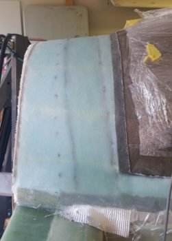
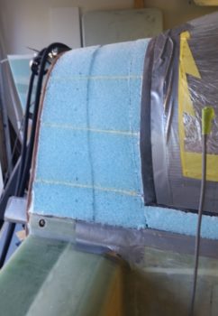
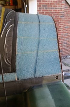
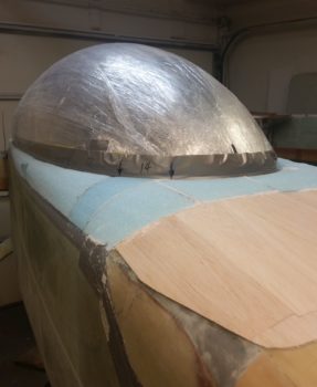
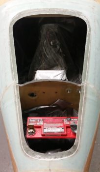
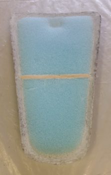
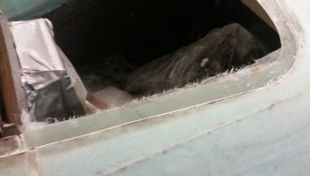
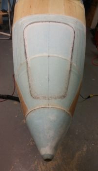
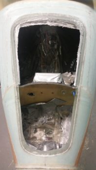
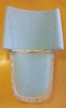
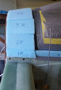
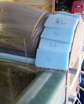
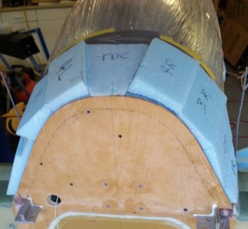
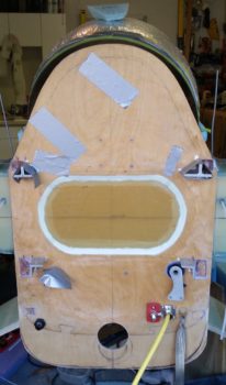
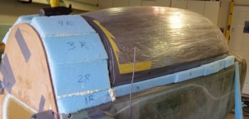
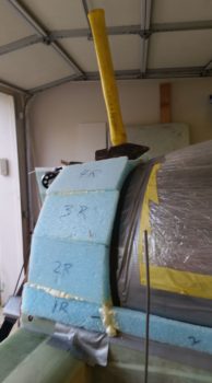
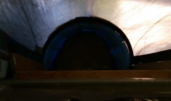
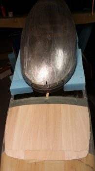
Here’s a shot from the aft end with the blue foam pieces peeking up above the perimeter edge of the firewall.  To be clear, the foam at this stage has been configured, but not installed in place yet.

After I got the “turtleback’s” blue foam blocks cut and sanded to a pleasing shape (ha… had to throw that in there!), I then set them aside to tape up the GIB headrest structure a little better to protect it from any nasty stuff.

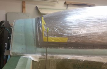
I also taped the longerons, leaving the aft ends exposed since that’s where the canopy structure that will remain on the aircraft side will get secured to.  Again, obviously I’m not doing my aft canopy area as per plans, and that includes the width of the canopy side aft structure, which will be a bit wider/longer than normal, while the structure coming off the firewall will be narrower than typical.  As a reminder, my aft canopy structure is patterned quite a bit after Wayne Blackler’s… although my canopy is way oversized compared to his more stock canopy size.

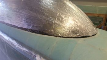
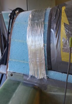
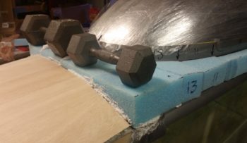
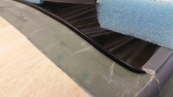
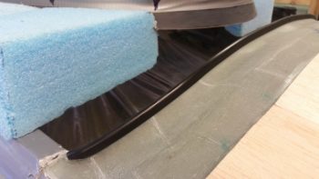
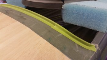
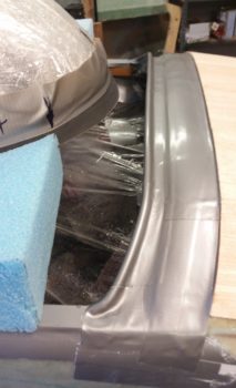
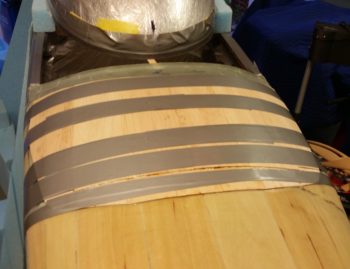
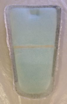
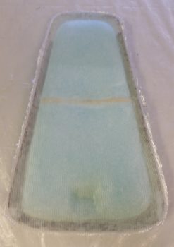
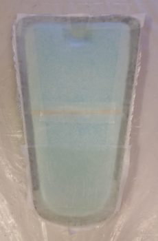
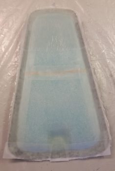
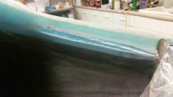
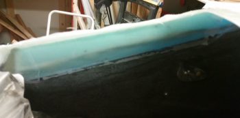
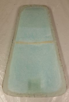
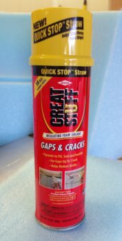
Since I was using spray foam in between the foam blocks, I decided to protect the aft edge of the canopy where glass will eventually get attached to.  The spray foam has a significantly strong hold and I didn’t want to have to be sanding it off of the aft canopy edge.

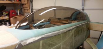
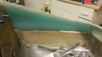
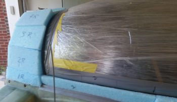
Now, I hate to point this out, but it’s another one of those “Sins of the Past” deals in that since my fuselage is a little off-balance symmetry wise, then it makes the canopy –which is following the curvature of the longerons– stick out about an 1/8″ more on the left side and pulls the right side over just a hair as well.  This IS noticeable from the aft side, especially with no engine or cowlings in place.

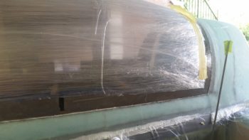
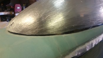
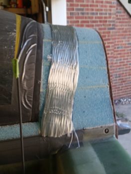
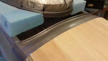
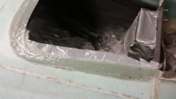
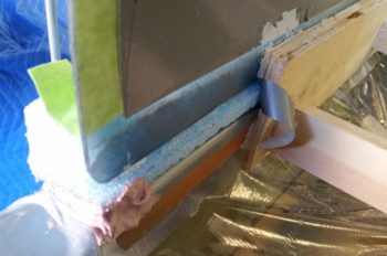
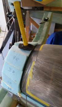
To mitigate this unsymmetrical dilemma as much as I could, I removed the spacer from the left side of the aft canopy spreader and pulled the canopy’s foam “frame” inboard to align the inside edge of the foam more with the inside edge of the longeron.  I then slathered it a bit with Bondo.

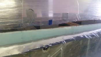
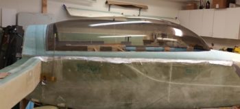
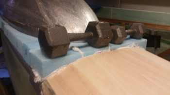
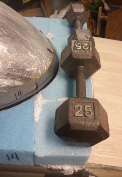
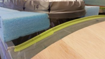
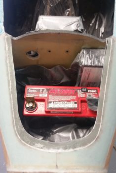
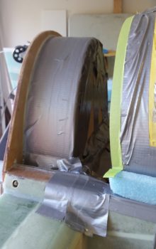
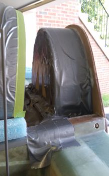
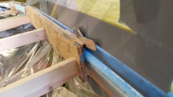
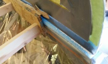
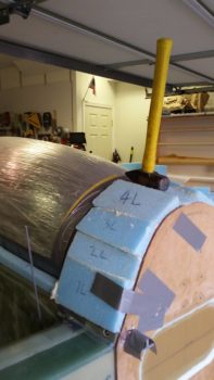
On the right side I simply tried wedging in a razor blade first, to split the glue seam and see if it did anything to get the right aft canopy to move outboard a bit.  It did, so I wedged in a mixing stick, etc. to get the very aft right side canopy to move outboard about 0.1″.  I included both pics since the top one shows the canopy spreader setup.

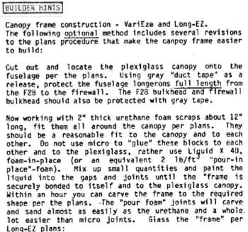
I then prepped for my craft project of assembling all the blue foam pieces between the aft canopy edge and the firewall to create a D-Deck/Turtleback, et al.  I had in my notes on the canopy build a little tidbit from CP 35 (shown below), and then just recently Mike Beasley also reminded me about using “pour-in-place” foam to secure the foam pieces together.  I should clarify that I used this foam just between the sides [“sides” here defined as actually top & bottom of each piece] of the foam pieces and still used micro on the aft canopy edge and around the perimeter of the firewall front face.

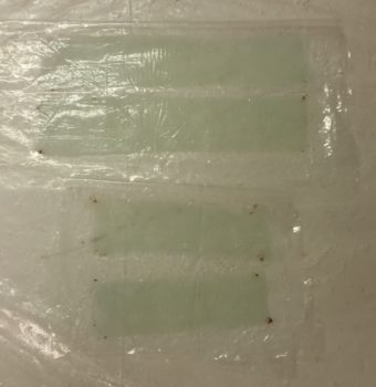
Here’s a screen shot of the first part of the CP 35 Builder Hint regarding using the “pour-in-place” foam.

Ahh, and then here’s the bias a lot companies have against us homebuilders! Basterds…ha!

I wanted to get this knocked out, so I used fast hardener in my epoxy.  It’s HOT here so man did I have to move out to get ‘er done!  But I did, and the micro was starting to get a bit gummy just as I was finishing up!

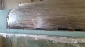
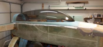
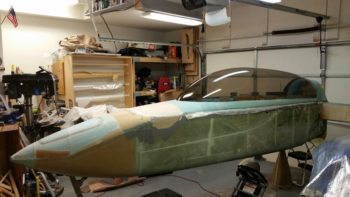
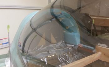
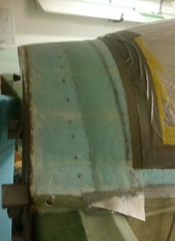
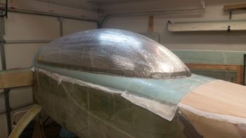
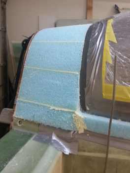
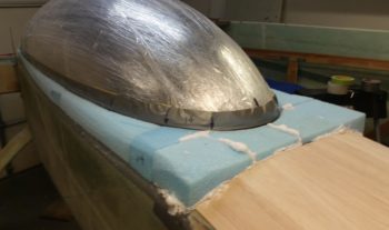
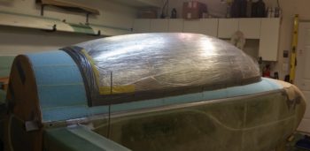
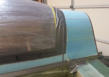
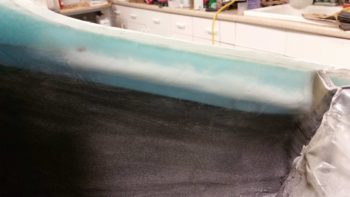
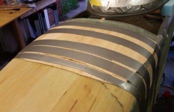
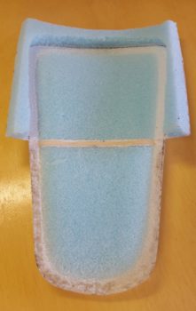
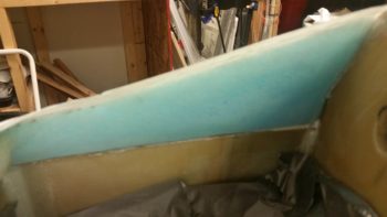
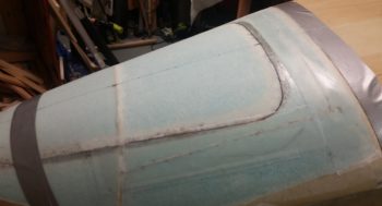
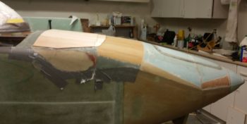
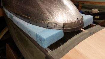
Here’s a wider angle shot of the freshly added “turtleback” blue foam along with the existing canopy foam along the right side.

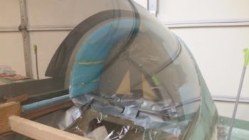
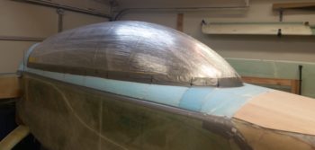
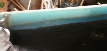
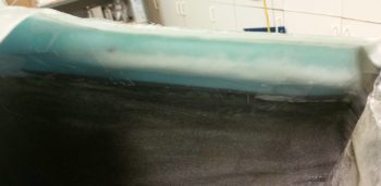
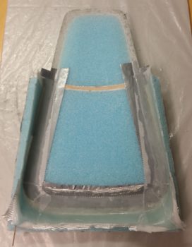
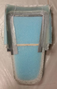
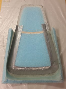
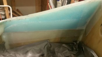
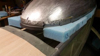
And here are shots of the freshly added blue foam to create the “turtleback” on the aft end of the canopy.  I have to say that I was really impressed with that spray foam, and I think it will do well.  To be clear, with the amount & type of glass that is getting laid up in this area, I have zero concerns about using this spray foam.

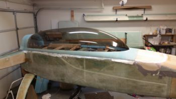
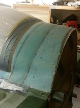
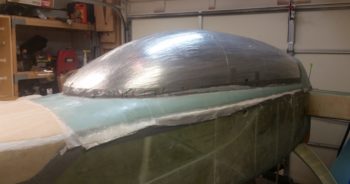
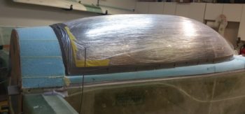
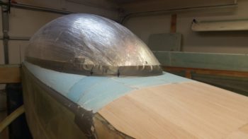
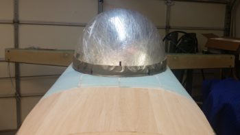
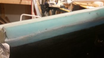
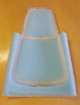
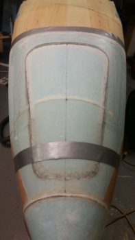
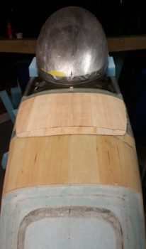
Another aft shot from the firewall.

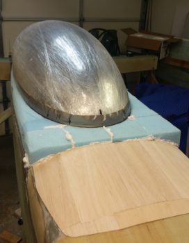
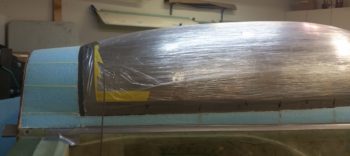
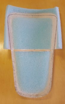
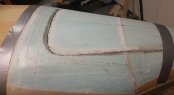
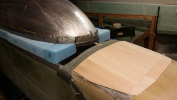
And finally a shot from above of the newly micro’d and foamed-in “D-Deck”.

It’s a bit hard to see (at least for the camera since I could see it plain as day), but peaking from under the front of the canopy I could see the seams between the blue foam pieces were pretty solid and by using this method I will have way, way less to carve to prep the interior surfaces for glass.

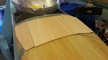
I knew that I was going to have to refigure, remark and re-tape my front canopy edge line since I added more height to the Aft Nose Cover on the back side of the cover…. using strips of 1/8″ thick Balsa wood.  I was going to have to readjust this line anyway, I just wanted to double check with the new Balsa wood in place.

Since it had been well over 24 hours since I had added the Balsa wood strips, I removed the securing tape.

I then took the long sanding board and did a good amount of fairing in on the added Balsa wood.

I then put a straight edge on the top of the newly added Balsa wood and marked the line on the canopy.  With the angle of the nose curving up as it goes aft, it meant that I was going to have to move the line up to 0.9″ on the front canopy edge, up from 0.4″.

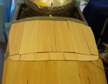
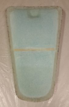
I pulled the tape off from around the front of the canopy and then marked the front edge of the canopy with hash marks at 0.9″ from the edge.  In the pic below you can actually see the strip of unsanded canopy above the original sanded strip.  After I re-taped the canopy edge I of course re-sanded the entire edge using 220 grit sandpaper.

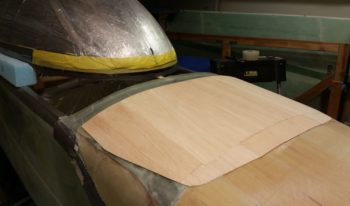
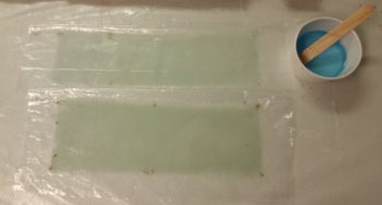
I then spent almost 2 more hours getting 2 foam block pieces shaped and micro’d in place on each forward side of the canopy.

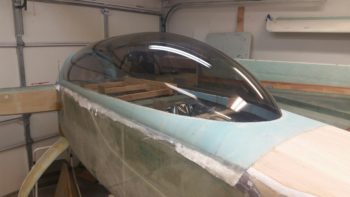
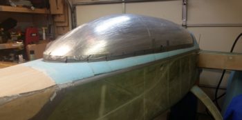
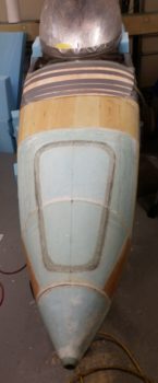
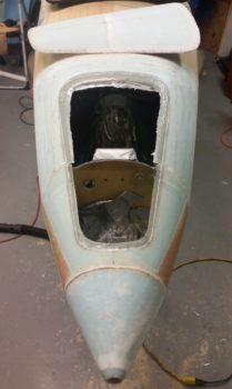
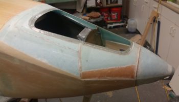
Here we have a wider angle shot showing the newly added foam pieces at the front of the canopy and the newly added 1/8″ thick Balsa wood plate on the Aft Nose Cover.

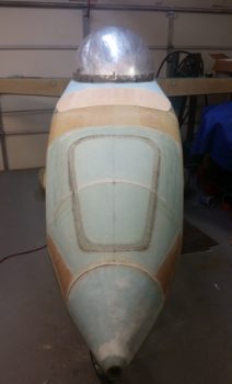
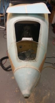
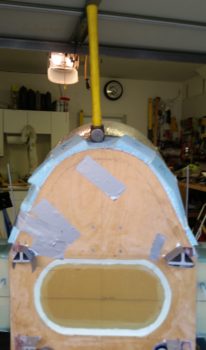
And a head on view of above.

I will reiterate that I do plan on getting a good bit of the canopy completed… at least to the point it’s strong enough to travel down to North Carolina on the back of the trailer when I haul the fuselage down there at the end of July.  However, I will make it a priority to start working on the house more since I got such a big chunk of the canopy (and Aft nose cover) both figured out to a more granular level and nearly completed.

Again, being a bit of a geek, my total calculated completion of foam on the canopy frame is at 91%.  But of course we all know that last 10% –the canopy/nose cover interface– will take a fair bit of time and effort to dial in!


Chapter 13 – New Tank-EZ!

I’ll explain the “Tank-EZ” comment a bit below, I just wanted to note that it’s amazing how happy one can feel just by having the right build materials on hand, especially when that includes BID fiberglass!  So nice to have it back in stock in my cutting table box!

I started off today by pulling peel ply and trimming up the overhanging glass on the top interior nose layups I did last night.  These layups really helped to reinforce the nose hatch flange and made the overhanging flanges stiff & strong.

I then took a few minutes to do a quick clean up job on the nose hatch flange itself.

Although this pic is a bit out of sequence, note the glassed nose hatch still fits like a charm.

So one thing I’m not overly pleased with on the current nose shape is that the ends of the F28 bulkhead protrude at the middle of the aft nose cover.  As I deduced the issue down I realized that it wasn’t that these front fuselage “corners” weren’t shaped with enough ferocity to remove a good amount of material, but rather that the aft top surface of the aft nose/avionics top deck cover was simple deflated a bit in posture and was not at the contour height that it should be.

After mulling it around in my brain these past few days, trying to decide if I was simply going to live with it (it wasn’t a show stopper to be certain) or if I was going to contend with this issue . . . but how?  I contemplated using some type of foam, be it pour foam or some standard build foam, but then with no narrow stock in abundant supply, I would have to order some or do a lot of sanding.  Yuk on both of these options.

Since I only needed about 1/8″ added thickness, but uniformly added across the top, I again turned to lightweight strips of wood.  Only this time just about the lightest wood you can get: Balsa wood.  I figured that would be close in weight to say, 1/8″ Divinycell if I had gone that route, and I simply wasn’t going to mess around with urethane foam or pour foam.

I will also point out that my decision to add some thickness and fill in the aft top section of the cover meant that the canopy build would be delayed a day or so as well as I contended with this cover addition.  The delay in the canopy build is simply due to the canopy skirt in the front interfacing with the aft nose cover, which must be completed first as a prerequisite task to dealing with the canopy’s front skirt configuration.

So while I was out running some errands I picked up some 1/8″ thick x 4″ wide Balsa wood strips. Upon returning back home I cut them up and set the strips in place on the top of the existing aft nose cover.

To help with the transition from the 1/8″ to the front side of the cover, I added a step using 1/16″ pieces of wood along the front edge of the 1/8″ thick strips.

My reference to “Tank-EZ” in the blog title is just a little blip on a term I have used in joking with Marco about how his Long-EZ would turn out heavy if he added an extra ply of BID or Kevlar to his aircraft structure.  I was thinking about that today, since I did add a layer of glass for these wood strips to lay upon, but as a transition piece of fresh epoxied glass, and also as form of filler to help fill in the lower point across the aft side of the cover. Regardless, it was extra glass, as will be the top piece of glass that will go over all this. Although it’s not a ton of added weight, it is some . . . so I noted to myself that perhaps my Long-EZ is at risk of becoming a Tank-EZ!

Here are a couple of shots with the new aft side wood pieces micro’d and glassed (bottom side) into place.

So I will work for a few hours tomorrow on the canopy, but it will not be an all day affair.  I must transition into house prep mode, and that starts tomorrow.


Chapter 13/18 – Gotta nose for it!

I had actually planned on getting some of today’s tasks completed yesterday after I returned home from North Carolina, but on the way back from NC I stopped off at fellow Long-EZ builder Chris Seats’ shop to check out his build, and of course didn’t end up leaving until 3 hours later!

I figured I would put in a couple of honest days to give the nose & canopy builds a solid shot in the arm since they do need to be done for the upcoming fuselage haul down to NC in about a month.  After that I’ll resort to the light build schedule.

Today I started out in pretty much pure research mode since I felt that before I could glass in the interior skin of the nose hatch I needed to have a good understanding of what was getting attached to it both hinge and latch wise.

After checking out a myriad of other builders’ blogs, etc, I headed down to the shop with some ideas to test out.  One idea in particular is that Nate Mullins is using a spring-loaded hinge that was designed for a cowling oil dipstick access door, but he repurposed it for the nose hatch.

I have one of those hinges that I bought for the cowling oil dipstick access door, but for the nose hatch I liked the idea of having a narrow depth on the hinge and getting it out of the way.  I tested it out a bit and realized that there was just no way it was going to work since my configuration is much different at the front of the nose hatch than what Nate has…. so I went back to the traditional hatch door hinge that we tend to use a lot in the canard world.  I have a template that I traced from a hinge template that Beagle sent me, that –like the nose hatch– is actually for a Berkut.  This hinge design is significantly smaller than the ones the Cozy Girrrls sell, which I have BTW and will be using on the aft nose cover.

After messing around with the configuration and testing different scaled sizes of this hinge, I finally came to the conclusion that the hinge pivot point must be as far forward as I can get it in the battery compartment, and the best size is the original size that I have from the template.  Moreover, with that knowledge in hand I now know that I will have to do some major rework on my interior top nose structure to get the hinges mounted in there, so I’m going to let ideas of just how to install the hinge pivot points germinate in my brain a bit.

After confirming the position of the nose hatch aft latch, I then got to work on doing a final shaping of the nose hatch interior foam.

I then glassed the interior nose hatch skin.

After laying up a ply of BID in the aft latch depression and across the front for more strength for the nose hatch securing components, I then laid up a ply of UNI followed by a ply of BID.

I then peel plied a good majority of the layup.

As the nose hatch cured, I then got busy on the top interior nose side walls, where the aft nose hatch perimeter flange is micro’d to the top of the side walls.  The angle between the bottom existing sidewalls and the new nose hatch perimeter flange piece added in is a bit sharper than I wanted, especially on the left side.

I Dremeled away all the excess micro and then sanded the inboard protruding intersection of the nose hatch perimeter flange with the top nose sidewalls.

NOTE: I won’t be messing around with the aft flange edge of the nose hatch since I need to prep the intermediate bulkhead area for securing the aft nose cover.  I’ll wait until all the urethane foam in-between F28 and the intermediate bulkhead –that I used as a mold/plug for the aft nose cover– is removed and access that area from the F22 area of the nose.

As I said before, since I broke through the glass on the right side about 4-5″ while I was extracting the aft hatch from the perimeter flange, I added a ply of BID for a total of 3 plies on the right hand side of the nose.  This BID will connect the existing nose sidewall to the added perimeter flange piece, and specifically add more plies to the flange itself.  On the left side I’m simply using 2 plies of BID in the BID tape.  Also, as you can see I prepregged the BID.

I then laid up the prepregged BID tapes on both the left and right side top nose sidewalls. I then peel plied the layups.

Here’s a shot of the glass peaking out from under the aft side nose hatch perimeter flange on both the left and right sides.

With the top interior nose wall layups completed, I then checked the nose hatch layup. The glass was cured about 80-90%, which was perfect for pulling peel ply and then razor trimming the edges of the layup.

The interior nose skin layup looked good and I didn’t see any issues with it!

Tomorrow I’ll be focusing on the canopy all day and would like to get the canopy frame to a point where I can glass it within the next day or two (I ordered 15 yards of BID that was delivered yesterday).


Chapter 23 – Exhaust Pipes

Of course I have no significant progress to report on the build today, but I did finally get around to cracking open the box that contained my exhaust pipes after all these years. Yes, I should have been more diligent and checked them much earlier, but I’m happy to report upon initial inspection that they look good.  And with that, they will be on their way to NC tomorrow!

Also, as I was getting ready to pack up a bunch of the Long-EZ stuff to go in this haul down to North Carolina, during a break I decided that I would detail the build areas that I’m “authorized” to build on from here on out until I am established down in NC and back up & running on the build.

If you’re curious at all, here are those areas:

  1. Canopy frame
  2. Nose hatch glassing & securing hinges/hardware
  3. Aft nose cover securing hinges/tabs/hardware
  4. Wheel pants hardware
  5. Baggage pods initial glass prep
  6. Cutting out ailerons/glassing aileron pocket shearweb

A very minor adjunct to that list is that I pulled 3 of the fuel tank ribs from the Feather Light strake leading edge kit to seal the ribs’ mouse hole edges with micro.

As you can see, half the items on the list are nothing more than facilitating hauling the fuselage down to NC with canopy, aft nose cover and nose hatch in place.  The other stuff is just for those occasions when I need to take a moment for some “me” time and spend a an hour or two feeling productive on the plane build <wink>.

So if whatever I look at build-wise is not on that list above, it simply gets packed up for the haul south.

Ok, report over…. back to packing!

Chapter 13 – By a nose…

Today was all about packing up for my next load down to North Carolina, but I of course had to see how the nose turned out.

I spent about 15 minutes pulling peel ply and cleaning up the nose.  The layups looked good without any issues.

I then carefully cut the perimeter of the aft side of the nose hatch door, but apparently not as carefully as the front half because I broke through on about 4″ on the right side.  When I glass the underside BID tapes on the right I’ll simply add a ply and extend up underneath the flange.  In fact, although I won’t add an extra ply, I’ll do the same on the aft side and the left side.

I then marked up the raw glass flange for a trim.

And then trimmed the aft side flange up with the Fein saw.  I may not have pointed it out when I discussed the flange layup on the aft half of the nose hatch door, but part of that layup was an extension of the flange across the Napster bulkhead forward.  These flange extensions turned out nicely, and later I’ll bridge the aft flange extensions to the forward side flange to make it all one solid flange around the entire perimeter of the nose hatch opening.

I then grabbed a quick side view.  A few hours later I went down to the shop to grab something, and decided to take about 15 minutes to clean up the peel ply boogers and edges from the battery compartment BID tape layups, so those are all clean and spiffy now as well.

I don’t have any other major build actions scheduled although tomorrow I do plan on at least roughly cutting out the remaining blue foam for the canopy.  I have quite a bit on hand and want to get a decent idea of what to leave behind since the rest is going down to NC.


Chapter 13 – Nose Tidbits

Since I didn’t have enough BID on hand to glass the canopy, I made today all about finishing up as much as I could on the nose.

I will say that –except for 1 external ply of BID (or perhaps 2 plies of UNI) and 3 BID tapes– the nose structure is FINISHED!

I started off the day with a quick check to see how the battery fit inside the nose compartment.  It fit like a champ and the only issue is the fact that to put the battery in or take it out I’ll have to remove the tool box.  No biggie really.

I then got to work on the nose hatch and the adjacent foam structure on the aft end that in reality is part of the nose structure of the aircraft, not the hatch’s.

I started off by identifying where the hatch outline was and then started cutting and digging out foam.

I got the hatch door cover side of the foam removed and the hatch outline door/opening line exposed, and some of the aft door foam shaped to match the front half foam.  Note that I trimmed down the little mini-bulkhead that had been in place as a sort of a template atop Napster’s head.

I really had some thinking to do and some decisions to make regarding the nose hatch, and specifically the adjacent foam structure…. as you can see, I didn’t leave myself much space at all to work with.  I knew this going in after I had mounted the nose sidewall pieces into place in the area between the intermediate bulkhead and Napster, but I thought it would be tight, but workable.

I considered cutting the bottom of the nose sidewalls to allow me to have a flatter approach on the nose side of the foam adjacent to the hatch door.  But then I asked myself why?

A few mental walk-throughs with the hatch assembly in hand told me that the only operational impact that having steep sides adjacent to the nose hatch door was that it looked different than the convention.  I could still make the steeper sides work, and I wasn’t impinging on anything within my nose.  Not to be Mr. Snarky, but I realized the only thing I would be impinging on is the standard that I’ve seen on a lot of canard nose hatches.  So, I pressed forward!

Now, the edge of the hatch opening on nose side in the few inches just forward of the rounded corner is fairly narrow, around 0.2″.  So I decided that instead of laying up the glass in an “L” shape coming off the sidewall, and trying to get a good glass-to-glass bond at the inside corner of the “L” shape, that I would just layup 2 flat strips of BID first with the edge of the glass nice and snug up to the edge of the foam.  Then I laid up 2 plies of BID coming off the foam side wall in a standard “L” shape.  Along the aft side of the nose hatch I went the standard 3 plies of BID and then in the corners I added an extra ply that overlapped quite a bit both inwards and forwards, giving the narrow edge areas an extra ply.

I then of course peel plied the layups since these edges will get BID tapes to secure them to the interior walls of the nose.

A number of hours later, I pulled the peel ply and cleaned up the layup.  The layup looked good and I felt confident that it was cured enough to get reinstalled into the nose.

However, to give the glassed nose hatch assembly just a little bit more time to cure, I then got to work laying up the BID tapes in the nose battery compartment.  As I mentioned at the beginning of the post, knocking these out would knock one more structure to-do item off the list in getting the nose pert near done.

Here’s some before shots of each side inside the nose battery compartment.

I then cut some glass and set up some prepreg assemblies for the BID tapes.  I then mixed up some epoxy and wetted out the glass.

After applying flox fillets in the corners and filling some gaps in the seams, I then laid up the BID tapes.  I then peel plied the BID tapes and left the layups alone to cure.

After finishing up with the BID tapes, it was time to micro, flox and glass the nose hatch and adjacent structure back into place in the nose.  I used micro on the foam and flox in the small seam on each side of the hatch on the aft side of what would be Napster’s ears.

I then laid up a 1-ply BID tape on the top and each side of the hatch door adjacent structure (plug) that had been removed along with the nose hatch door . . . the layups overlapping onto the nose skin of course.  I then peel plied the layup in preparation for the one final layup that the nose will get.

Tomorrow I’ll cut out the nose hatch door to check how everything looks inside, but that’s pretty much it since I’ll be in full on packing mode for the next haul down to NC (I did a bit of prep today, but no real packing . . . so gotta get on it!)