Chapter 18 – Front inside canopy

My friend and realtor Mindy came over this morning to discuss selling my house and also to see the progress on the Long-EZ build, which she had not seen yet in person. So before she got here I spent a good couple of hours today straightening up, which included a good 45-minute cleanup of the shop.

We then discussed the plane build for a good while as I showed her the fuselage and then the panel avionics and EFIS goodies.  After discussing house-selling stuff for a bit we went to lunch and BS’d even a bit more…. all this to say that my morning and afternoon was pretty much used up on Mindy’s visit, which was quite productive in itself.  BTW, during her visit I removed the canopy from the fuselage to enable her to look inside the fuselage.

I got down to the shop a bit after 5pm and got to work making a PVC foam plug for a hardpoint that I’ll have in the front right corner of the canopy to mount what is essentially a hook to keep the canopy front lip from lifting up in the airstream.

The PVC foam plug is 0.8″ deep and comes to within a 1/4″ of the glassed outer surface of the canopy.

Using a piece of 1/16″ thick G10 Garolite I made a 2x K1000-3 nutplate for the front right corner canopy “hook.”

I also made a K1000-6 nutplate assembly for the right front canopy corner to allow mounting a small 1/16″ aluminum spacer plate on the canopy, whereas another 1/16″ spacer plate will be floxed to the top of the longeron.  Obviously added together they will make up a 1/8″ gap which is very close to optimal for compression of the canopy seal. [The left side has a hardpoint where I would mount the nutplate assembly, so I’m waiting until after the internal canopy frame is glassed to figure it out].

I glued the two pieces above in place using micro and flox and then left them alone to allow them to cure.

I then got busy on the mess that awaited me regarding the canopy front underside skirt layup.  I was correct in that the glass did in fact get folded up underneath itself and thus jammed multiple layers up into the groove and –worse yet– off the aft wall of the glare shield interfacing groove.

It took over 2-1/2 hours to get the front canopy skirt trimmed, cleaned up, and sanded with the extra glass down in the groove removed.

I then set the canopy back in place on top of the fuselage.  The elevation of the canopy vs the aft nose cover looked great…. in fact, at most in any dimension the mismatch is about 0.030″ or less… max.

Here are a couple shots of the canopy skirt and aft nose cover interface . . . not bad!

Since it was getting late, and knowing that it was too late to use the Dremel or Fein saw, I decided to get nearly everything prepped for the canopy forward interior 3-ply layup. Since the layup is “U” shaped, I decided to go with 2 pieces of BID per ply to conserve BID and simply overlap all of them…. below you can see the 6 pieces of BID that will make up 3 plies.

Here’s a wide angle shot of the prep to glass in the next forward plies of BID at the front canopy loop.

If you look closely you can see that I used a razor knife at all the edges that will enable a flox corner.  Since the flox is the only thing touching both inside and outside glass where it meets in the outboard corner, I wanted to make sure that the bond was robust so I’ll wait until tomorrow to Dremel the interior crud off of the inside glass (I can’t do it tonight because of HOA rules and just wanting to be nice to my neighbors!)

Tomorrow I’ll continue working on the canopy to try to get it well on its way before hauling it down to NC.


Chapter 18 – Canopy skirt glass

Having figured out last night how much of the foam needed to be removed for glass, I started today by removing foam and micro from the very outboard edges of the canopy skirt underside.

I Dremelled both the channel groove and the edges and then sanded the bare glass part of the edges with 36 grit sandpaper.

I then spent a good half hour using the Dremel tool to remove the foam down to just shy of 1/16″ as best as I could.  Of course that made quite a mess . . .

After getting the foam removed as evenly as possible –to make room for the 4 plies of BID– I then slathered up the foam surfaces with micro slurry first and then with some thick micro.  On the front and side edges I used flocro, heavier on the flox.

I then laid up the 4 plies of BID just from the aft wall of the groove to the front edge of the canopy underside skirt.

I then peel plied the lay up.

I wanted the layup to be well on its way to being cured before I flipped it back onto the fuselage/glareshield, and it was getting fairly sticky (vs wet).  But when I remounted the canopy –to ensure the canopy underside skirt layup would cure perfectly formed to the glare shield– something was amiss.  I piled a bunch of weights on the very front portion of the canopy skirt, and it was laying down fairly well…. but it still seemed like 4 plies of BID in this configuration should not be that thick.

Well, I finally found a spot on the left side of the canopy frame where I could peer into the right underside of the canopy skirt.  I didn’t see any peel ply and as I had suspected it meant the aft wall of the groove had been caught up into the groove versus hanging freely.  I took all the weights off, had to lever the front of the canopy up… which I just lifted up around 6″ to then straighten out the glass in the groove.  The issue was the aft canopy frame (i.e. turtleback) was pushing the canopy forward as the entire canopy settled into place, so there was very little spacing between the aft edge of the glare shield and the aft wall of the canopy skirt groove.

I tried as best possible to ensure all the glass was where it was supposed to be and then set the canopy back down in place.  I then piled all the weights back up on top of it.  It did seem better, but it may still need some tweaking after it cures.

While the canopy underside front skirt layup cured I then started on the initial sanding and shaping of the Metal Glaze that I slathered onto the roll bar-attached canopy gas strut mounting tab.  The great thing about Metal Glaze is also probably one of its worst qualities in handling, it’s tough when cured so it took me over an hour just for this initial shaping.

Here’s a shot of the aft side initial shaping of the Metal Glaze.  It rained most of the day today, so tomorrow I plan on getting the final shape dialed in at which point I’ll take the roll bar outside and hit the welded on canopy gas strut mounting tab with a couple coats of primer.

I also plan on getting the remaining front interior portion of the canopy glassed as well as the foam underside of the turtleback structure.  IF I have enough time tomorrow I’ll also glass the aft internal canopy frame.


Chapter 18 – Cheating 101

After returning back from North Carolina this evening I wanted to get at least a couple things knocked off the to-do list.

Since it was past 8 pm by the time I got into the shop I felt I should get the noisy stuff out of the way first.  I grabbed the Dremel tool and ground down & shaped the rather grotesque welds I had made to hold the canopy gas strut mounting tab to the roll bar support tube.

Here’s the aft side (sorry for the blurriness, I loaded these after I was done applying metal glaze….) and the front side of the gas strut mounting tab, with my grinding job visible.

Then, with Metal Glaze, I slathered up the welds, transitions, and marks made to clear the paint off of the tubing for the original welding.

I was still settling in from my trip, which included baking another batch of desiccant to re-energize it for the engine dehydrator system.  By the time I had a good window of time to glass the canopy front skirt, it was a bit late.  Tired from my trip I decided to simply prep the glare shield with tape to knock out the layup and hit it hard tomorrow.

Tomorrow I plan to continue with the canopy build to get it and the nose build as far along as possible before I put the fuselage on a trailer next week to haul it down to NC.


Chapter 18 – Canopy Strut Mount Tab

I started off today spending a good hour cleaning up all the overhanging glass, epoxy runs, stuck on tape, etc. before doing a near-final shaping of the canopy hard points with the Fein saw and hard sanding board.

Below, starting from the left front of the canopy, you have the following cleaned and shaped hard points: forward canopy latch, safety catch, #2 of 4 canopy latch, #3 of 4 canopy latch, and aft canopy latch.

I then got busy making up a thick paper template for the canopy gas strut mounting tab that I decided quite a long time ago would get welded towards the bottom of the right roll bar support tube.

Another shot of my proposed canopy strut mounting tab.  With the multiple angles of the roll bar support tube, it took a number of iterations to get the bottom mounting indentation correct.

This spot on the roll bar support tube sets the mounting tab correctly so that it will be the correct distance forward and parallel to the canopy cross strut, and also at the correct height above the longeron (2″ seems to be the accepted standard…. at least that’s what my buddy Dave B. told me!)

I wanted to ensure I had a good piece of metal stock to make this mounting tab out of, so I scrounged around and found a piece 0.1″ thick 4130 steel . . . perfect!

I then marked up the mounting tab outline onto the 4130 steel.  At this point I just needed to confirm the shape would work and then cut it out!

After getting the canopy hardpoints glassed, according to the plans you place the canopy back onto the fuselage to check the fit, finish and clearances between canopy and fuselage.

So far so good…. everything seems to fit well!

I’ll say again, I’m really happy so far with my canopy skirt to aft nose cover intersection.

I then peeled pack a bit of the outer protective plastic to reveal the canopy strut mounting tab inside the canopy. (These pics are of the same thing…. just a slightly different perspective).

After seeing the amount of space available for my canopy strut mounting tab, I decided to shift the straighter edge from the inboard side to the outboard side, allowing me to move the canopy strut mounting hole outboard 0.5″… more towards the pivot location of the canopy hinges.

I was going to remove the canopy to swap out the original canopy strut mounting tab cutout with the newly shaped one, but then discovered that I could just carefully lift up the right side of the canopy.  I wedged it open while I taped the new/modified canopy strut mounting tab in place.

I then grabbed a shot of the newly shaped canopy strut mounting tab through the canopy. I like this shape much better because it utilizes more available space.

I then marked up the newly shaped canopy strut mounting tab onto the 4130 steel.

And then cut out the actual mounting tab from the 4130 steel plate.  Here are the iterations of the canopy strut mounting tab design below.

I then test fitted the freshly cut canopy strut mounting tab onto the rollbar support tube. You may also note that I removed the paint off of the support tube in prep for welding the tab into place.

I also ensured that with the lower shape of the mounting tab that I could get the tab parallel to the pilot’s seat back (which would be parallel to the canopy cross strut).

I then mocked up the canopy gas strut onto the mounting tab.

With everything looking good, I removed the roll bar from the fuselage and placed it onto my welding table.  I of course had to pull out my welding kit and set it up as well.

A few more minor trims and I finally had the shape of the canopy strut mounting tab dialed in.

I then proceeded to lay down some hideous looking welds, although this tab is now attached to the roll bar like nobody’s business.  Tonight was clearly not a great welding night, although I am out of practice on TIG, and I had a few minor issues.  For one, I was welding a 0.1″ thick straight piece of metal to a 0.065″ thick tube.  So I had to be careful of both getting a good flow of metal while not blowing out the side of the tube, which I did a couple of times but was able to quickly flow in some welding rod to fill the holes!

Also, I had initially just planned on tack welding this tab in place, but then decided to string the welds together which turned out to be just that: nothing more than a string of tack welds!

Another shot of the canopy strut mounting tab welded onto the roll bar.

Well, as I quite often respond when people ask me if I welded something…. “I’m not that great of a welder, but I’m a hell of a grinder!”  So, I’ll grind down just a bit of the ugliness, slather up the weld with Bondo and then shoot it with paint a bit later.  That should do the trick and hide my disgusting welds!

BTW, when I mocked up the tab while on the fuselage, I aligned it with the pilot’s seat back.  Well, not thinking about my curved roll bar base –which follows the curve of the fuselage– when I had it on the welding table I aligned the mounting tab to the roll bar side. Thus the reason the tab angles in slightly on the inboard (left) side . . . Yep, an oops but it makes zero negative impact in the operation of the canopy gas support strut.

Here’s another shot of the canopy strut mounting tab.

This time around I actually mounted the canopy gas strut by bolting it into place.  So far so good!

And a final shot of my canopy strut mounting tab welded to my roll bar.

Tomorrow is pack out day and then another quick haul down to NC.  Moreover, having just welded the canopy strut mounting tab into place on the roll bar knocks out the last of my immediate welding tasks on this airplane build which allows me to then pack up the last of my welders and my entire welding kit to haul down to NC.

In addition, I’m nearly out of epoxy and will order another gallon so that it will be on hand when I get back from NC.  In the time I have after I return to prep the fuselage and canopy, I do plan on getting the interior canopy frame glassed before it goes on the trailer!


Chapter 18 – Hardpoints Glassed!

It’s interesting that when looking down the road at required build tasks some things pop out as seemingly challenging but then they end up being fairly routine, while there’s other tasks that you barely make mention of mentally, mere background noise, that in your mind should merely take hours but end up taking days . . . in other words, predicting man-hours spent in all the wrong places!

Ahh, thus is exactly the case with the canopy hard points!  Who knew they’d take so long or be such pain in the backside?!  Regardless, no matter how long it took, the canopy hard points are glassed!

I started today by pulling the peel ply off the canopy forward hinge hard points and inspecting the layups…. they looked fine.

I then curved the outer edges and tops of the last round of foam additions I made for the 2 aft canopy latch hard points on the left side canopy frame.  The forward of these 2 hard points was already at the exact width I needed, 1.85″ while the aft hard point needed a little narrowing so I sanded it down to 1.85″ width as well.

I then laid up 2 plies of BID on the forward hardpoint of this pair, canopy latch #3 of 4.

And then also laid up 2 plies of BID on the aft canopy latch hardpoint.

I would like to note that these 2 aft protruding canopy latch hard points (above) are 1 of 2 options that I have for mounting the canopy latch hardware.  As per plans, the standard canopy latches will get mounted with bolts running vertically.  However, if I find these hardpoints too obtrusive, unsightly or the plans method of latch catch installation too problematic, I reserve the right to shave these off and mount new latches (which I would have to cut out of flat aluminum, see pic below left) which would mount with the hardware installed horizontally (pic below right).

Option #2 is a blatant copy of Mike Beasley’s outstanding work that he did on his canopy, which is pretty close in size & shape to mine (from what I can tell pic wise).  I nabbed these pics off Mike’s very informative Long-EZ build site.

One final point of note on my 2 canopy latch options is A) for option #1 I already have all but one set of latch hardware in hand, and B) since these hard points traverse the width of the canopy frame, it’s clearly much easier to lop off the protruding hardpoint section to go with option #2 than it would be to add it later if I wanted to go with option #1.

Moving on.

With the 2 aft canopy latch hardpoint retaining glass laid up, I then spent about 5 minutes per forward left side hardpoint with the Fein saw for an initial cleanup.  Here is the aft most hardpoint of the 3 that had an accelerated curing event (not quite your typical “violent” exotherm).

Here’s the middle of the 3 forward hard points, which will be where the safety catch will get mounted.  I had a pic of the forward hardpoint as well, but it was very blurry so I deleted it.

I will say that trimming off the nasty tops and then digging down into these front 3 hard points proved to be the normal arduous task of trimming solid flox & glass.  Although not pictured, I later dug down into this hardpoint almost 1.5″ and found nothing to be concerned about structure wise.  And given each of these hard points weren’t quite full when I stopped, with about 3/8″ more of new flox and BID required to get them to level with the bottom canopy frame, I’m very confident there is no structural issue with these hardpoints (I did a fair bit of research as well and from what I could ascertain 160-200° curing temps are not damaging in any manner to a layup).

And here we have the 2 forward hard points on the right side for the forward canopy hinge after I pulled the peel ply.  I then hit the hard points with the Dremel tool to clean them up a bit.

I then got to work on the right side aft canopy hinge hard points.

I dug the foam and dead micro out, pulled the peel ply on the inside of the newly applied “retaining wall” glass and prepped them for the BID/wet flox hard point mix.

This time around I decided to avoid any exothermic type reaction so I simply use slow hardener and filled each hardpoint up only about 2/3rds of the way.  I then peel plied each hardpoint.  The plan was after the first round cured I would then pull the peel ply and top off each hardpoint hole in an attempt to minimize any excessive curing heat.

Here you can see the aft hinge hard point holes filled with wet flox and BID, but not all the way.  The layup mixture is peel plied and allowed to cure before another final round of wet flox/BID mixed was added to fill the hardpoint holes level with the foam canopy frame.

I then dug out and cleaned up the hardpoint hole for canopy latch #3 of 4….

And the canopy aft latch hardpoint.

Here we have the 2 aft canopy latch hard points ready for their wet flox/BID concoctions.

It was getting toward the end of the evening and I wanted to get the aft canopy corners cut off since I needed to first use my battery powered “skil” saw to trim down the canopy’s wood support frame to allow access –if you can call it that!– to get the Fein saw in to lop off the aft lower corner of each canopy side.  You can see the visible green cut line. [Note: all the above power tools make a lot of noise, and it was getting late… my community homeowners association and I already have a strained relationship….. so…. ya know!]

I then cut off the lower aft corner of the right side canopy frame.

I discussed this in an earlier post, where I noted I couldn’t just do this during canopy removal because I had duct tape under the aft canopy frame as a release agent.  This piece will be attached to the aft side turtleback (sans duct tape) and will allow the forward part of the upper cowling’s protruding shoulder (faintly marked on the side of the turtleback) to be installed without any clearance issues (if my prognosticating is correct!).  It also provides clearance for the canopy when it is opened with the forward part of the cowling shoulder structure.

Here I’ve done the same on the left side, lopping off the lower aft corner of the canopy (seen in background) to add it onto the left side turtleback structure.

Here’s a tandem shot of the new turtleback additions.

And I couple wider angle shots.  I left the first pic even though it’s blurry to get an idea of how these turtleback lower corner additions will look.

And a final shot of the canopy with the lower aft corners lopped off.  Now, to be clear this is not a design feature dreamed up by me –although admittedly I’ve come up with a few doozies!– but rather the quickest, most acceptable response to having to contend with the upper cowling shoulders and ensuring clearance for the canopy to open without hindrance.  Obviously I only needed this for the right side, but doing both sides makes the canopy and turtleback symmetrical.  So, if you don’t like it, than bicker at Mike Melvill –the guy who designed these cowlings– next time you see him . . . not me! haha!

Ok, so jumping ahead about 5 hours, I finally completed glassing ALL the canopy hard points . . . whew!  As I said at the beginning of this post, I would not have expected these darn things to take so long.

Here’s a shot of the right side canopy hinge hard points.

And the 4 canopy latch (remember, I added a latch) and safety catch hard points.

The aft 4 hard points on the left side canopy frame.

And the aft 2 canopy latch hard points.

Finally, we have the front canopy latch hardpoint, floxed, glassed and peel plied.

Tomorrow I’ll continue with some tasks on the canopy, but I need to start packing since I’ll be taking a quick load down to North Carolina in a couple of days.  I will then return, do a mad blitz to finish as much as I can to make the fuselage road worthy before I load it up and haul it down to NC as well on 1 August.


Chapter 18 – Canopy, my canopy!

I should note starting off that it took me a bit of research and thought yesterday to figure out that I needed what was essentially an interior “wall” to retain the wet flox & BID that goes into all the component hard points on the canopy frame.  Thus the reason for a layup of 2-3 plies of BID –above and beyond the normal layup schedule– at each hardpoint location.

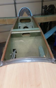
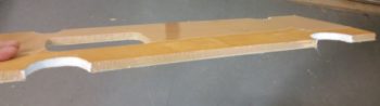
I started off today with another long round of more refined clean up of the canopy frame.  I Dremelled off a lot of dead micro, and also Dremelled a small trench around the front edge of the canopy about a foot in each direction from CL.  Like the top side per plans, I’ll also lay up the first ply with the glass going into this trench and fill it with flox.

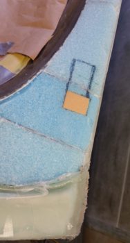
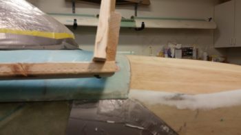
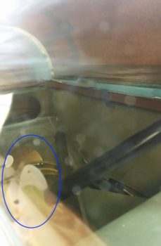
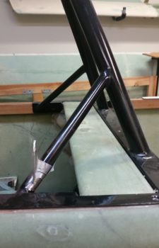
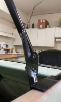
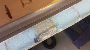
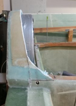
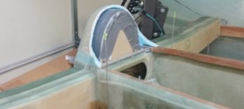
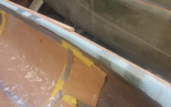
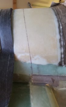
I then got to prepping the right front hinge location for a retainer layup, as I mention above. The plans denote a 1.5″ thick (over normal width longerons… more on that below) canopy frame where it contacts the longerons, but since my canopy rail matches the thickness of the longeron (~0.8″) on the front half, I needed to ensure I maintain (or make) my hard points at the 1.5″ width.  As it goes, at the front end of my canopy frame it’s not difficult to obtain or keep the 1.5″ width for the hard points.

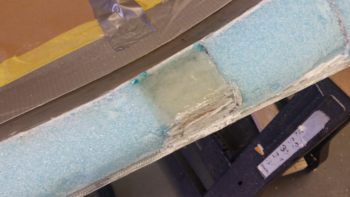
But I digress, back on the front hinge hard points, I used micro on the areas that would not get dug out and then placed raw epoxy and then a patch of peel ply over each actual hard point spot.

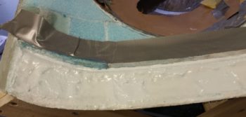
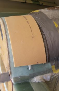
I then laid up my prepregged 2 plies of BID over the hard points, and then peel plied that since the final interior canopy frame layup will cover this glass.

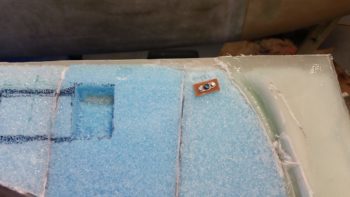
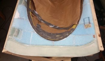
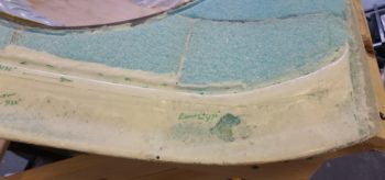
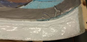
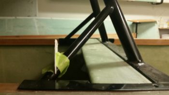
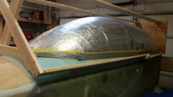
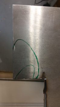
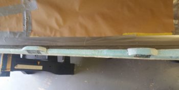
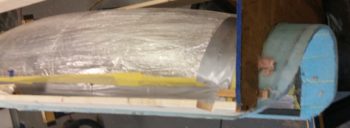
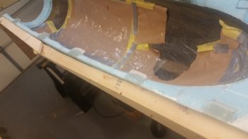
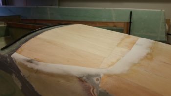
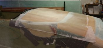
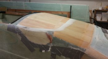
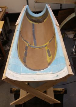
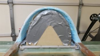
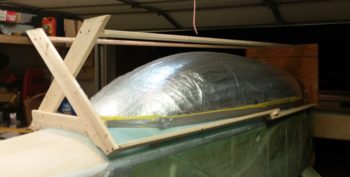
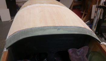
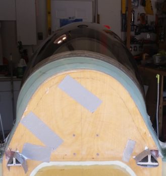
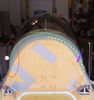
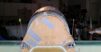
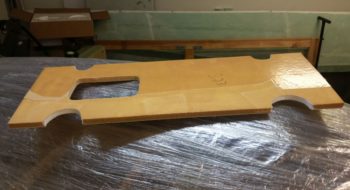
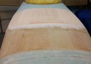
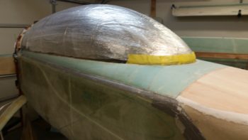
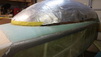
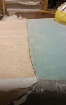
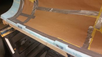
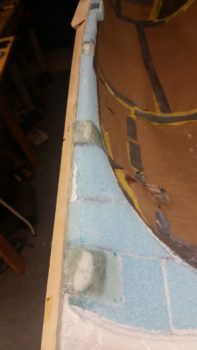
I then taped off the back right half of the canopy along the “glass-to” line that matches the exterior glass line of the canopy.  I then sanded the bare canopy edge to give it texture to grip the interior glass when it’s laid up.

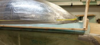
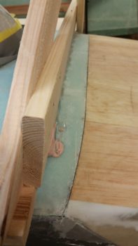
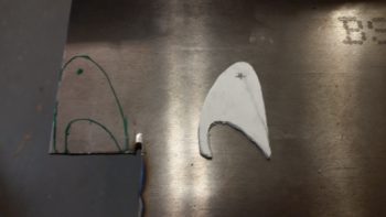
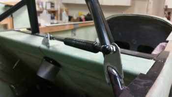
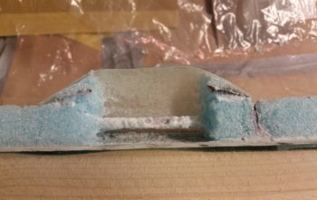
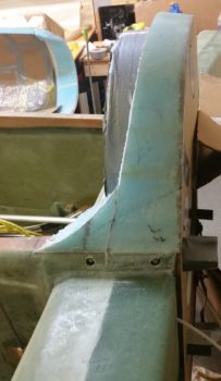
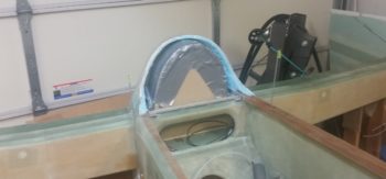
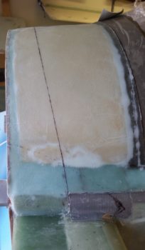
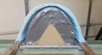
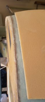
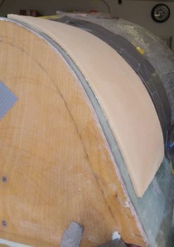
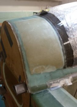
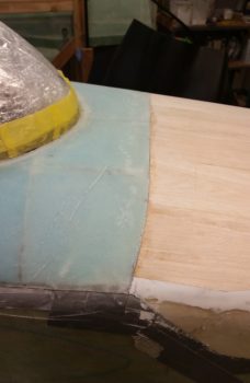
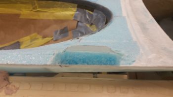
Since I don’t have 1.5″ of foam frame here, I manufactured it by shaping a piece of foam that will get micro’d to the existing foam rail.  I made it “L” shaped so that it also rests on the bottom half of the exposed canopy edge, with plenty of room for glass above it.

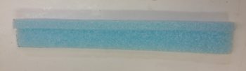
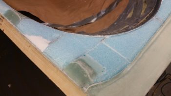
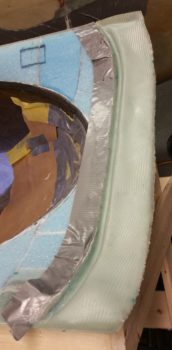
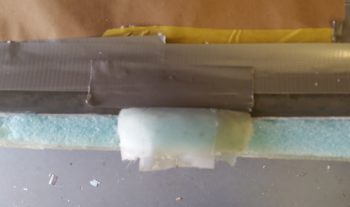
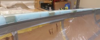
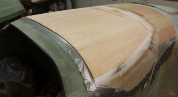
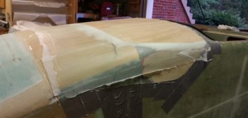
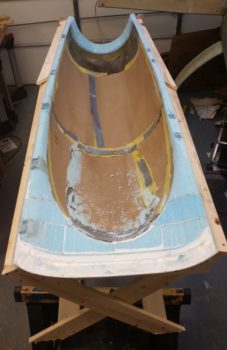
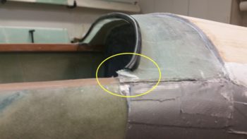
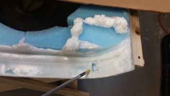
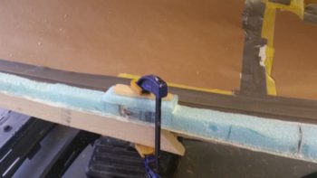
I then micro’d the additional foam piece in place that then gave me 1.5″ wide on the canopy rail right at the right side canopy aft hinge hard points.  The foam piece extends 1″ beyond the hardpoint segment forward & aft to allow for a transition back to the existing narrower canopy frame.

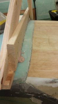
I then made up another piece, only for one hardpoint, on the other side for the #3 of 4 canopy latch.

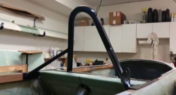
[NOTE:  I’m going with 4 canopy latches.  Here’s why:  My canopy goes much further aft than plans, plus I have a longer aft canopy frame.  In addition to that little factoid, I don’t have a good option for keeping/incorporating the middle latch in the same place due to my roll bar frame.  If I move the middle latch forward 2″ than I can just barely clear the frame, but since I have the entire kit from Jack Wilhemson, pre-made, then I only have enough of the long rod (tube) that then forces me to move the aft latch forward about the same as the middle latch.  So, I have much more canopy + frame aft, but then I’d be moving my aft latch forward a minimum of 2″.  I don’t much care to do that.  I’d rather move the aft latch back an inch, move my middle latch forward 2″ and then fill that gap in with another latch.  With a MUCH bigger canopy than stock I think I wouldn’t mind having one more securing latch anyway!]

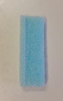
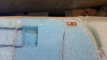
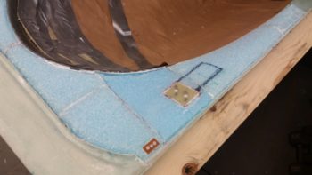
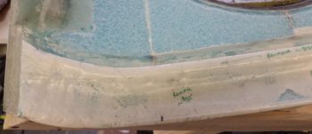
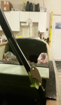
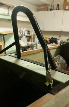
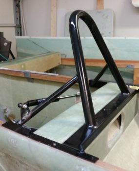
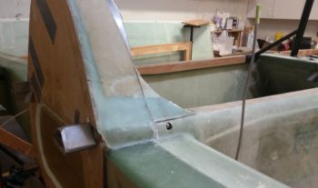
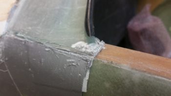
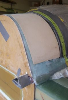
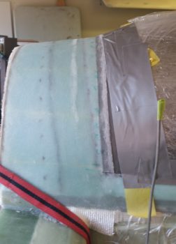
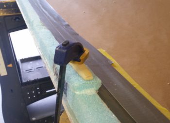
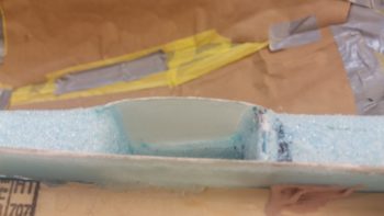
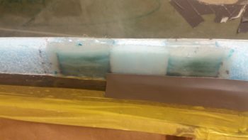
Here’s the foam piece micro’d in place for the #3 of 4 canopy latch, that will be located just aft of the roll bar frame.

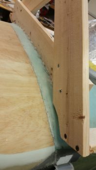
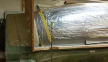
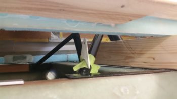
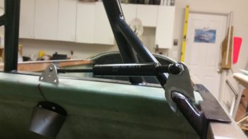
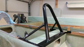
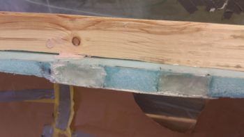
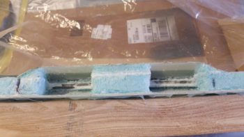
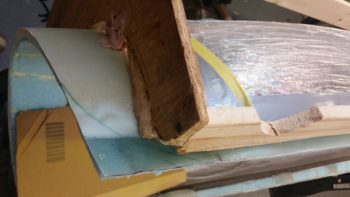
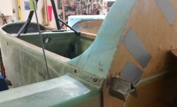
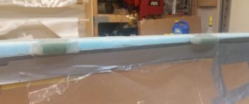
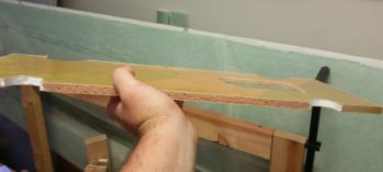
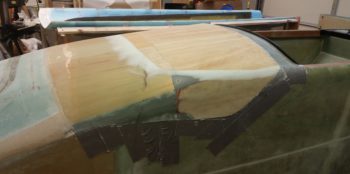
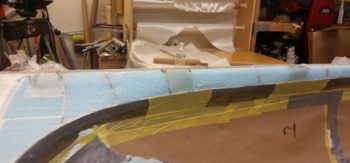
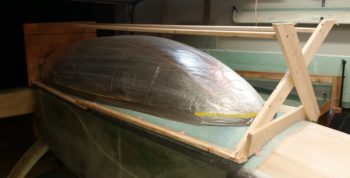
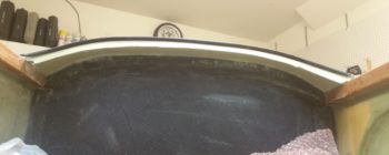
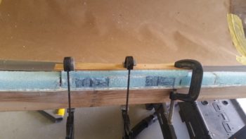
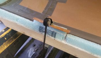
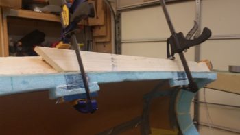
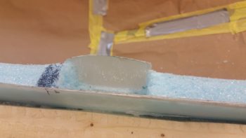
I then cut another piece of foam (quickly, since I had leftover micro) and clamped it in place on the left side aft canopy frame.  This foam piece will of course make up the left aft canopy latch hardpoint.

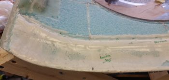
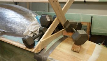
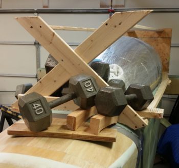
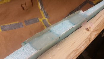
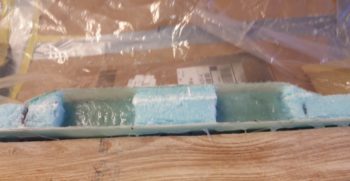
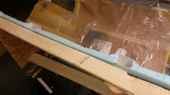
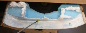
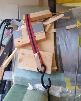
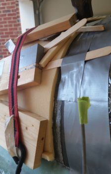
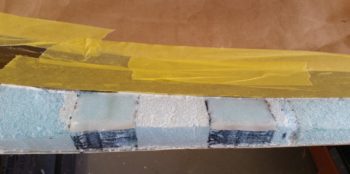
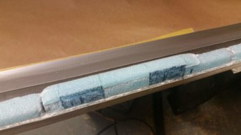
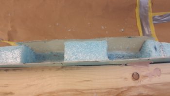
So, here are the foam pieces (incorrect width! more on that below…) for the aft 2 canopy latches, secured in place with clamps while the micro cures.

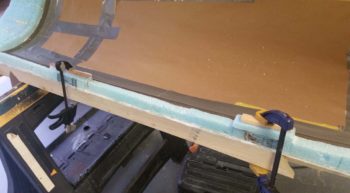
And a bit a later after the micro cured…. look nice eh?  But again, wrong width!

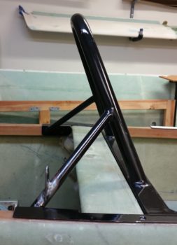
My mindset the whole day had been geared towards the aft hinge hardpoint, which, no matter what size the longeron is needs to be 1.5″ minimum width to have a good foundation for mounting the hinges to.

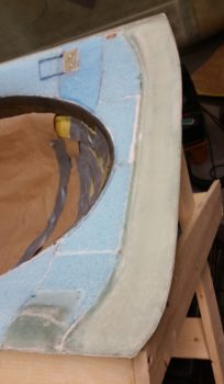
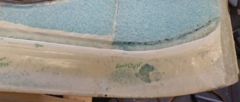
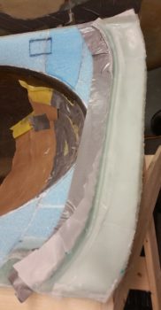
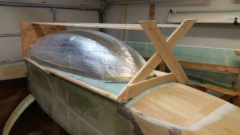
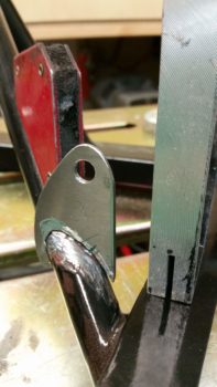
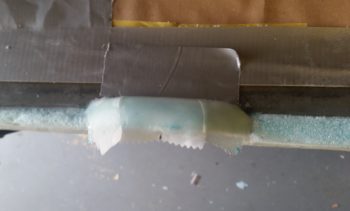
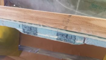
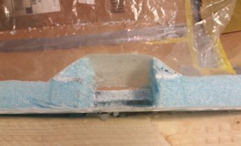
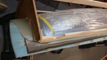
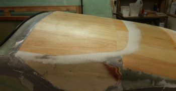
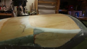
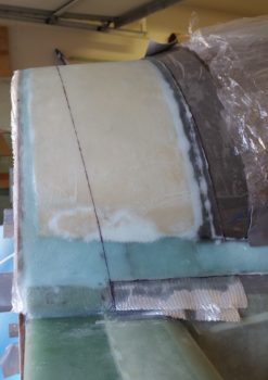
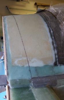
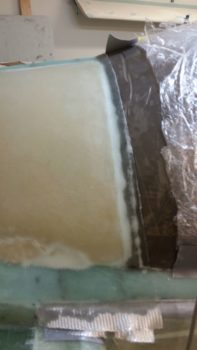
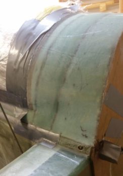
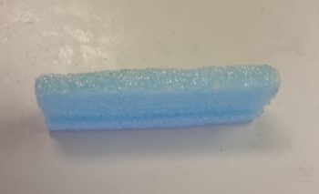
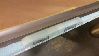
With that in mind, I got busy shaping/curving the top side of the added foam so it made a nice transition into the canopy edge.

I prepped it in the same fashion as the front hinge hard points and as I was finishing up the 3 ply BID layup I was thinking about my next task: glassing the 2 hardpoint retaining layups on the other side…. I then had a DOH! moment.

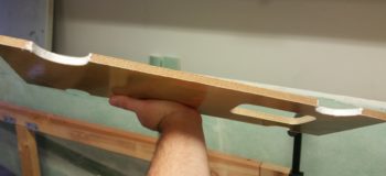
As I mentioned, no matter what size the longerons are, the 1.5″ wide hardpoint works fine for the hinge hard points, but that is not the case with the canopy latch hard points, which MUST overhang the longeron inboard since the latch assemblies attach inboard of the longeron.  Remember, from the pilot’s seat aft my longerons are a hair over 1″ wide, so a 1.5″ wide hardpoint works for a 0.7″ wide longeron, but not a 1″ wide longeron.  Ugh!  The good news is that I caught my error before I glassed in the retaining layups at these hard points.

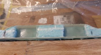
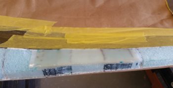
Again, having some left over micro, I quickly made up 2 more additions to bring the canopy frame inboard a minimum of 0.35″ to allow enough hardpoint for the latch assembly to attach to.  The foam pieces are a bit thicker than required, but of course I’ll just sand them down to the proper thickness before glassing the retaining layups.

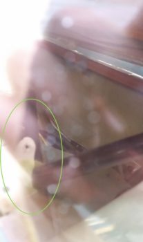
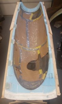
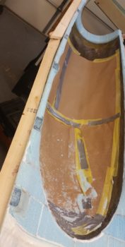
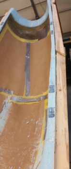
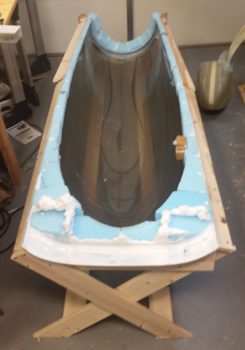
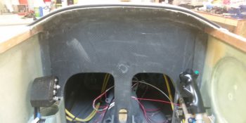
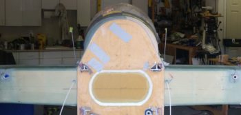
I then got busy digging out the foam and removing the inboard peel ply off the 3 left side forward hardpoints . . .

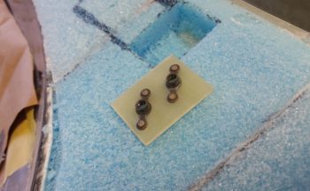
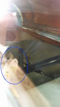
And the two forward right side hinge hard points.

BTW, although these layups were fairly fresh and I used NO micro on the foam surface where I applied the peel ply, it was still amazingly difficult to remove…. each hardpoint took a good 10 minutes in just removing the peel ply!

About this time in the evening is when everything turned magical, and by magical, I mean it went south ….. a bit.  Kinda weird and still assessing!

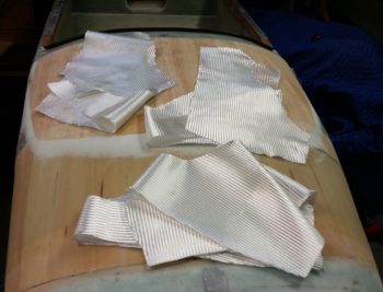
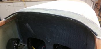
I started off by rereading the plans and then proceeded to glass in the 3 hard points along the front left side canopy frame.  I knew from accounts from other builders that 15 plies in these hard points, especially the deeper ones I had, was simply a fantasy and that it required a whole lot more than that.  I gathered up all my BID scraps, whipped up some flox using my “slow” hardener (75/25 slow/fast) to a point where it was right at the cusp of being wet flox (i.e. towards the thicker side of wet flox), and got to work.

Ok, first off, my bad for not taking into account the heat in my shop.  It was HOT outside and well over 80° F in my shop.  Secondly, I had never encountered an issue with a large scale exotherm type event with anything other than using fast hardener.  IIRC, in Germany I had an exotherm with a huge cup of epoxy when I left it sitting there for a good while when I was doing something really big like the wings or fuselage, and one event when I used fast hardener for the filling in the one of the elevator hinges . . . which resulted in it spitting the flox right out of the hole.

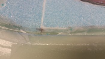
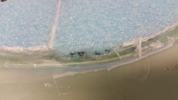
But just as I was a few plies from finishing up these holes, I started to see some bubbling around the edges of each hole.  I felt the sides of the retaining glass and it was hot, so I grabbed my thermometer.  I got one reading at 201° F for a blip, but couldn’t replicate it. Most of the readings on all the surfaces on or around the hardpoint layups were in the range 160-195° F.

I had a couple of small leaks around the retaining glass layups going on which had annoyed me since I had to keep wiping up epoxy running down the inside of the canopy (one of the few times I’ve used paper vs plastic, and I got a fair bit of epoxy running down the paper!)…. however, I think these leak areas worked to allow the heat to vent and the layups to stay in place with no expulsion action going on.  I continued to monitor the temps as there was no discoloration of glass on the top side of the canopy frame and no melting foam anywhere.

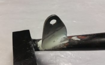
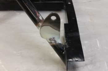
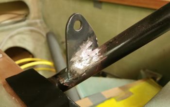
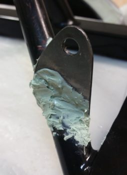
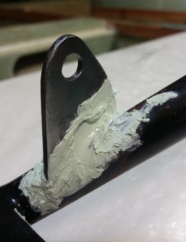
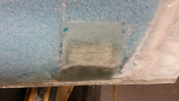
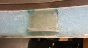
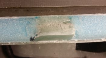
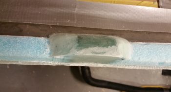
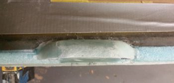
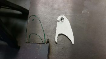
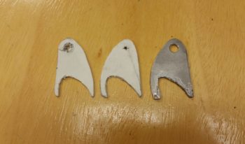
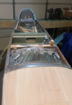
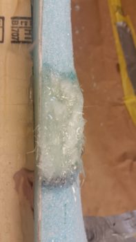
Out of curiosity I tried to add a bit of flox to the top side of each layup just to use it up and get the final 0.2″ of fill on each hole.  However, when the flox hit the bubbling brew on each hole it just burned out immediately and turned white (as you can see in the pics below).

The layups stayed warm for quite a while, but again, except for one non-repeatable blip just over 200°, I never saw any dangerous temps.  I’ll cut a core out of one of the hard points to see if it is solid [it should be, it was filled with glass] and check to see if the epoxy/flox just cured overly fast or if it burned out.

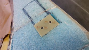
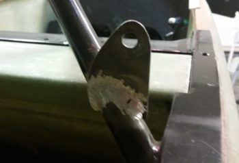
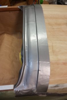
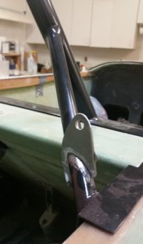
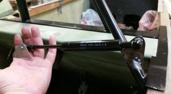
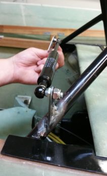
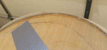
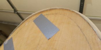
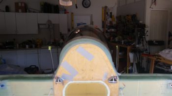
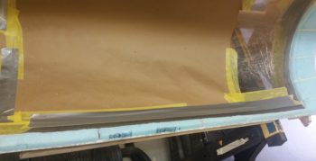
Having learned my lesson, I then grabbed a can of straight SLOW hardener and got to work on the right front hinge hard points.  Note the duct tape on the front hardpoint… this tape plays a key role in the next part of my story.

You see, as I was filling up the 2 front hinge hard points, I thought to myself the front hard point must be bigger than the back one, because the back one is filling up noticeably quicker with the same amount of flox and glass going in.  That’s when I realized the front hardpoint was leaking and thus harder to maintain the same level as the aft hardpoint.

Seeing that I wasn’t going to win this game, and almost out of flox in my cup, I simply cut a piece of peel ply for each hole and set the peel ply in place.  I would simple finish these holes with flox paste tomorrow and call it a day.  I did a final wipe down of all the epoxy that had run down into the canopy onto my thick brown paper, and knew I’d be back one more time for some cleaning before heading to bed.  And with that, I went upstairs and took a shower.


When I returned to clean up the epoxy mess caused by the leaking front hardpoint, what did I find?!  These hardpoint layups –with straight SLOW hardener– both had some minor bubbling going on around the edges!  I grabbed the IR thermometer again and checked temps (again!) and sure enough, same range as the left side: 160-195° F.  Highest temp I saw on this side was 198° . . .  amazing.  Again, no discolored or burned glass or foam anywhere, just a really hot curing layup. (sorry, no pic of this tonight but I’ll grab one for tomorrow’s post).

So, I cleaned up the epoxy, went upstairs to spend some time uploading the pics for this post and returned about 45 minutes later.  The temps were still fairly high, although significantly cooler (130-150° F), and the epoxy leak had stopped, so I did a final cleanup of the epoxy and pulled out the wet tape and paper from inside the canopy to ensure I had no curing flox or epoxy on the inside canopy surface…. thankfully it was really clean and nothing had really gotten onto the canopy.

Since the weather temps are high here and my canopy hard points are significantly deep, for the last 4 hard points I will fill them halfway and then peel ply the layup, and then finish it after it cures.  All I can say is wow.  I guess my technique of trying to follow the plans is more hazardous than stuffing the holes with BID and pouring wet flox in & around it!

All part of the struggle I guess of building these airplanes!


Chapter 13/18 – Canopy hard points

I started off today by doing one final sanding of the aft nose cover –specifically where I added height by installing 1/8″ thick Balsa strips– and prepped it for glassing.  I then applied a bit more micro to do one final smoothing of the transition between the added Balsa wood and the originally glassed aft nose cover.

I also added some protective duct tape at the aft end to protect the intersection with the glare shield.

I then laid up the 1 ply of BID on the aft nose cover, which should do it for the major glassing on the cover.

I then peel plied the layup.

One last shot of the peel plied final major layup in the aft nose cover.

I took the leftover micro and knocked out another strake rib by filing in the mouse holes with the micro … almost!  I then realized I forgot the cutout in the middle part of the rib! That will need micro on the last 2 recent ribs that I’ve just done.

Jumping ahead a few hours –to stay on course thematically!– the layup on the aft nose cover was essentially cured.  Here it is after I pulled the peel ply.

A view from the nose (always nice!).

Moving on to the canopy, I then set the canopy structure up on saw horses.

And then spent a good while cleaning it up… a lot of dead hot glue and micro needed to come off!

I realized that I just couldn’t add the myriad of layers of flox and BID for the hardpoints with my canopy rails configured like they are . . . there’s just not enough meat to do it, nor is the shape of the side foam (mine are more vertical vs. horizontal) conducive to constructing hard points in the traditional plans manner.  Thus, I decided to add inboard sidewalls just for the hard points and for retaining, restraining & containing the BID and flox laid into each hardpoint.

I peel plied the underside (outboard) side of each BID pad for these 3 front left side hard points (from left: front canopy latch, canopy safety catch, and middle canopy latch) and also the inboard side so that I could add the normal glass layup schedule right over these pads.

I also did a bit of assessing on the right side canopy’s hard points for the 2 hinges.

Finally, I marked the thickness and did an initial trim of the the right side interior turtleback foam (I couldn’t easily get to the left side because it’s a bit too crowded currently on that side…. plus, it was late!).

Tomorrow my goal is to get all the hard points laid in and curing.  I also plan to get the canopy interior glass laid up by Tuesday so that after my next short trip to North Carolina I can get the canopy mounted in place with the hinges.


Chapter 18 – Canopy removed

I started off today by marking the cut line that will separate the turtleback from the aft canopy frame.  To reiterate, not only is the overall combined length of the turtleback and canopy frame significantly shorter on my airplane that per plans, but the ratio is much different in that the canopy frame is longer than the turtleback. This is opposite the configuration than the way the plans has it.

I also cut the overhanging/excess glass from the latest layup over the added 1/4″ foam piece.

I then did a quick mockup of the upper engine cowling to determine where the shoulders of the upper cowling were located –these shoulders are a unique feature of the Mike Melvill CF cowlings.

I marked the shoulder interface and then extrapolated where the turtleback & CS spar portion of the slope that extends from the cowling shoulder would be.  I won’t be using this information now, but I did want an idea of what I’ll need to do down the road to prep for this configuration issue.

Not really having contended with the upper cowling “shoulder” issue and how the requisite forward wedge/coned shaped piece that terminates just forward of the CS Spar front face means that I will have to cut off the lower aft corner of the canopy frame and reattach it to the front bottom corner of the turtleback-to-longeron intersection.  Clearly I couldn’t do it at this point because the releasing duct tape that I placed between the bottom of the canopy frame structure and the longerons prevents any permanent structure to remain at this point.  It simply has to be done one the tape is removed.

After I cut the turtleback-aft canopy frame line with the Fein saw, I then took a few hour break to go run some errands and pick up some 1×3 and 1×4 pieces of wood for the canopy brace that I then constructed around the canopy frame before I removed the canopy from the fuselage.

Here’s the finished canopy frame constructed to remove the canopy from the fuselage.

I ended up having to use Bondo in a few key places to ensure the wood strips along the side would stay in place.  I also used it on each end to reinforce the vertical parts.

I went upstairs for a bit while the Bondo cured, and when I returned back to the shop the canopy was ready for removal.

I have to say that with the 1/8″ spacers in place on top of both longerons, the canopy removal wasn’t that big of an issue.  It took a little over half an hour and I had the canopy off and on the floor inverted.

I should note that before I started in on the canopy removal in earnest, I reached up through the hell hole and used a 1×2 ACS shipping piece of wood to knock loose the aft canopy vertical spreader cross support boards that were wedged and hot glued into place.

Of course there was a bit of a mess on/around/in the fuselage when I removed the canopy, but I had it all cleaned up in fairly short order.

I also cleaned some of the foam gunk out of the channel between the GIB headrest and the interior foam wall (currently) of the turtleback.

Part of cleaning up the fuselage involved finally ripping out the foam and tape that I used as a form to create the glare shield.  The pic below is the first time I’ve seen my glare shield without any form underneath of it.

And here’s a quick pick of the glare shield with rubber edging in place.

I then proceeded to spend as much time or more than I did removing the canopy on cleaning up the “melted” duct tape (very gummy) from off the top of the glare shield.

I also grabbed a shot of the underneath side of the glare shield structure.

Now, because I was sticking a knife underneath the canopy edge to work it loose, there was some slight collateral damage in that the right aft outboard corner of the glare shield got dinged up a bit…. as did the left side actually!

I also put a decent sized gouge on the underside of the canopy front skirt.

Speaking of the underside of the canopy front skirt, I have to say I’m extremely happy with how the pour foam filled in the gaps and contoured in spot on fashion with the raised aft lip of the glare shield.

Finally, I liked the way this look so I snapped a shot of it.  Here we have a new version of the fuselage with the canopy off again.

Tomorrow my goal will be to get the interior canopy frame shaped and the hard points glassed at a minimum.  If possible, I would like to layup the canopy’s interior glass… but that may be pushing it a bit.


Chapter 13/21 – Turtleback tweak

First off, I know I’m spending a number hours more per day than I had planned on this canopy… however, I both want to clean up what I consider a big SNAFU on my turtleback and get the canopy acceptably configured for transport.

Defining the turtleback issue:

In the pic below, note the 9 O’Clock bulge and the 1-2 O’clock deflation.  I think I unknowingly did this by forcing the canopy bottom corners both over to the right before placing the turtleback foam in place.  Actually, I did notice it, but I thought it was a very slight, minute shape shift. It just wasn’t obvious nor clear that it would become so obvious and prominent after shaping and glassing the turtleback.

I wanted you to see the pic below, with the turtleback unmarked and in its current “natural” state.

The turtleback shape mitigation plan:

Here is my analysis of how to minimize the misshapen turtleback, and as you can see in the pic below I’ve marked it up to explain my mitigation plan.

First off, let me reiterate and be clear that my plan is to MITIGATE this off-balanced issue as best possible.  I have NO illusions of completely eliminating it.  The only true fix would be to rip off the canopy and redo the whole thing, with my entire focus then being how to mitigate this configuration debacle on the aft end vs (again) eliminating it.  And of course risking the chance of screwing up the very nice outcome of the front 90% of the canopy!

Problem #1 is the bulge on the left side, denoted in the pic below with the red oval and the white star being the apex of the bulge.  Note how below the star the canopy is vertical to almost coming back inboard.  Contrast this with the other side (right) where it has a comparatively gentle sloping curve, much more constant in nature.  To be clear, the aft canopy edge drove the shape of the turtleback so the only thing further outboard than that canopy bulge on the right is the 3 plies of BID holding it in place.

The REASON this shapeshifting occurred was most likely my maniacal –and probably misplaced/misguided– adherence to keeping the center canopy elevation even with the upper engine cowling extended contour angle (denoted by the green arrow and line).  If I had adjusted the canopy and let the elevation of the top go where it wanted to naturally, I think I’d still be dealing with this configuration oddity, but just in a less severe form.

Yet another issue, that will actually help in the attempted remedy of this SNAFU, is that for some mysterious reason –despite many repeated measurements– the fore/aft vertical canopy line of the turtleback glass overlaying the aft edge of the canopy is 0.35″ aft on the right side than it is on the left… which I’ve denoted with the blue line.  This obviously means the left is more pronounced when looking at the turtleback from CL aft as in this pic because its termination line is 0.35″ forward than the right side.  Making the bulge even more pronounced!

My plan is a 2 step plan.  First is to fill in the area marked by the yellow dashed line with 1/4″ foam and shape it.  Focusing on trying to manufacture a right side apex (purple line) opposite the left one.  I will also very aggressively sand the left side along the apex line to knock that down as much as possible.  Even 0.020″ will make a difference.

Part of the deflation between the 12 O’clock and 3 O’Clock positions is that on the left side my sanded depression for the 3″ UNI tape was close to spot on and it was even with the other foam surface, whereas on the right I went just a hair deeper and the UNI tape is not proud nor even, and is ever so slightly sunken… but not enough to affect the glass transition with the overlying BID.  It just adds to the depressed/flat/deflated look on that right side.

Now, I say a 2 step plan due to the fact that I feel I can/should deal with the turtleback to canopy angle issue later, after I get the upper cowling in place.  However, IMO I need to see if this remedy for the right side will work effectively BEFORE I pull the canopy off to shape and glass the interior surfaces.  If it just doesn’t work, I may go further in my corrective actions.

One final thought on the remedy to my unsightly creation, which actually isn’t really a remedy but rather of byproduct of the shape and configuration of my plane’s major components.  The bulkiness, size and shape of the canopy does a good job of hiding this issue from the front.  It will most likely be more noticeable with the airplane in the grazing position because it naturally takes more of the canopy’s sheer size –that serves to block the turtleback from view– out of play.  The other saving grace for my surreptitious cover up here is that the cylinder humps on each side of the upper cowling serve to block the view of the lower half/third of each turtleback side when viewing it from the back side of the plane (determined by my holding the cowling in place and assessing the aft view with cowling in place).

Clearly what I’ve shown here in these 2 pics is NOT visible (to my knowledge) in any of the pics I’ve taken at other angles.  Since you can’t be on separate sides of the airplane at the same time, I think if I add mass to the right side and mitigate the off balance between the two sides it would be really hard to get a really good view of this abomination at any other angle other than straight forward or aft of the plane.

Finally, I’m not trying to hide bad workmanship and be done with it.  Clearly there are no structural issues at play here and it’s my belief that any airflow imbalance will be minimal.  But for the sake of getting this thing in the air, and also to not waste any more time, materials, or money, I want the best mitigation possible and point out the view-blocking components as a point of note.  No builder wants a glaring, non-structural issue being the focal point that eyes are drawn to on their creation as it sits on the ramp!

So I started today by trimming the overhanging cured glass from around the firewall.

Here’s a side shot of the overhanging glass over the firewall’s aft edge.

Here we have the glass trimmed away that was hanging over the firewall and also the 1/4″ thick Divinycell foam that I micro’d to the right side turtleback.

I then did an initial round of sanding on the added foam, as well as cleaned up some micro runs.

Here’s the 1/4″ thick added foam piece sanded and shaped down close to its final shape before glassing.

Here you can see that, although still not perfect, the addition of the foam has taken the shape & aft view of the turtleback from “Ooh, gross!” to “Hmm, it’s not horrible…”

I then micro’d the foam and glassed it with 2 plies of BID.  I used an extra ply to allow me to really hit it hard with a sanding block if need be when it comes time to finish the surface for paint… with the micro finish allowing me to further fine tune the turtleback’s shape and symmetry as well.

Here’s a shot of the shaped & glassed foam added to the right side of the turtleback

This pic shows the newly positioned line of the canopy to turtleback intersection.

Before I got busy sanding and shaping the added turtleback foam, I Fein saw cut the aft edges of the canopy at the longerons.  Here’s the left side, but I forgot to grab a shot of it on the right side before I reglassed the added foam piece.

I also took a few minutes to dig out the foam in the mouse holes on one of the 3 strake ribs that I left out of the last haul to NC.  I’ll try to knock these out as I go about my other build tasks so they’re ready when it comes time to build the strakes in the next 2-3 months.

I also took a little bit of time to take the long sanding board and really finalize the shape of both the flocro transition for the added Balsa wood strips on the aft nose cover, as well as the intersection of the “old” nose sidewalls and the new foam I just recently added to make up the forward nose sidewalls.

[I have some slight “shoulders” on the nose sides right where I added in the new PVC foam when creating the top nose structure.  I sanded these for a bit but I think I have to accept the fact that since I left my original nose sidewalls a bit high and with a vertical surface, that the nose then somewhat sharply transitions into the top curve… this makes for a somewhat abrupt change at the nose sides from curved (top) to vertical (side).  So although curved, it’s not as smooth as I would want.  A minor issue, as I think it has zero affect on nose structure strength or aerodynamics, and I suspect not highly noticeable when the nose is finished to paint.]

Here are some closer up shots of the flocro transitions between the edge of the added Balsa wood and the front/side areas of the aft nose cover.  To be clear, the height of the front edge of the balsa wood was about 1/32″ when I applied this flocro, so there is not a ton of added flocro added here.

Tomorrow I plan on actually cutting the turtleback to separate the aft canopy frame and then remove the canopy from the fuselage to begin canopy internal shaping & glassing.


Chapter 18 – Canopy Tweaks

The external canopy layup has passed the 48 hour mark for curing, but before I pop the canopy off the fuselage to shape and glass the inside I need to contend with one of two issues involving the turtleback (aka turtledeck, D-Deck, etc.).

The issue that I’m not contending with today is the profile angle between the turtleback and canopy.  I’ll deal with that once the upper cowling is mounted and I know the exact angle I’m dealing with.

In regards to the other issue, as you may be able to see below –which coincidently I clearly DID NOT/COULD NOT see before I glassed the canopy frame– is that the turtledeck is a bit curvier on the left side, a bit flatter on the right side and a bit deflated on the upper right side.  This all comes down to one thing really:   Sins of the past.

With my fuselage being slightly askew, although virtually imperceptible to the naked (or unaware) eye, it seemingly took its toll on the aft canopy to turtleback interface . . . although I tried (in vain) to mitigate it as best possible before glassing.

A sideline issue that may actually help mitigate the issue above is that the vertical seams between the turtleback and canopy are at different Fuselage Stations, with the right side corner being about 3/8″ aft of the left side.  This should actually help my mitigation actions (note that I’m not saying “fix” actions because I think the configuration is such that I should be able to mitigate the turtleback imbalance to a good degree, but not eliminate it altogether) since it will give me more space forward for another layup that I will add to this structure.

Yes, it may be hard to tell, but underneath that strap and all those boards and wedges is a 1/4″ thick piece of PVC foam that I will sand and shape down to fill in the low spots on the right side turtleback.

Here’s a closer shot . . . Again, there will be no way to completely eliminate the offset of the turtleback without redoing the entire canopy install (that is NOT going to happen!), but I am cautiously optimistic that this will help balance it out to a good degree.

With the aft extra foam piece in place, I then spent about 45 min marking and trimming the overhanging glass from the sides of the canopy, starting on the right side first.

I then did the same on the left.  The edge will most certainly require more work before final canopy install, but so far it’s looking pretty good.

I then spent some time cleaning up the intersection between the canopy front skirt edge and the aft edge of the nose cover.  Again, this is the rough start to this process, but so far the lines are looking pretty good and the elevation glass-wise will be very close between the two structures once I get a ply of BID on the aft nose cover (which I now plan to do after I remove the canopy from the fuselage).  I also took about 15 minutes to sand down the flocro transition around the Balsa wood on the aft nose cover.

Tomorrow I’ll sand and shape the foam I added to the right side turtleback to (hopefully) create a better turtleback transition that balances with the left side.  I then plan on laying up 2 plies of BID on the new turtleback foam.  Once that cures I plan on cutting the turtleback-canopy split line and then removing the canopy from the fuselage (after I build a wood frame around the canopy to support the it inverted and off the fuselage).  I also plan on laying up the final ply of BID on the aft nose cover.