Chapter 23 – Less baffling Baffles

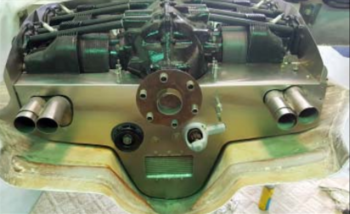
My intent today was to knock out the top center flange on the bottom cowling, to get it cleaned up and glassed (CF) with a more pleasing rounded shape.  But that didn’t happen.  With multiple communications with different canardians regarding baffles going on throughout the day, that only served to spawn more questions, and more curiosity, on various specifics regarding my baffles.  In short, it ended up being another baffle oriented day, albeit unintentional.

My first quick task out of the gate was to simply trim the VAN’s baffle kit oil cooler support bracket that I won’t use in that manner since clearly my oil cooler is not getting mounted to the baffles as it might in some tractor aircraft.

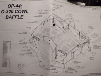
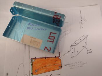
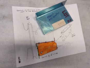
I copied and highlighted the diagram that Mike Melvill hand drew and included in his how-to manual for his cowlings.  The diagram depicts a very basic (no dimensions) overview of the bracket he used to attach to the right side of the engine —just forward of the flywheel/alternator pulley— that supports the aft baffle shelf & skirt.

As you can see with the VAN’s oil cooler mounting bracket, it just has a few extra tabs that prevent it from being used as the Melvill bracket.  Grant it, some subsequent trimming will almost definitely be required, but the basic configuration is baked into this VAN’s bracket.

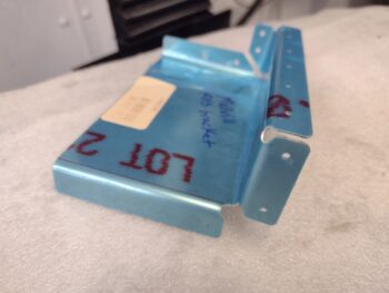
I marked the cut lines on the VAN’s bracket and lopped off the tabs on 3 sides… and Voila!  A Melvill baffling bracket I now have on hand!

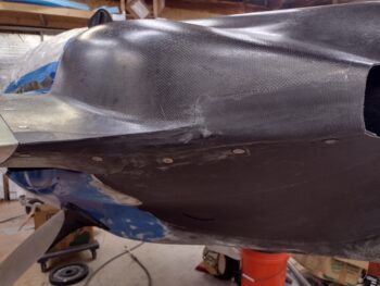
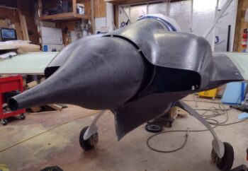
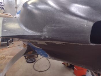
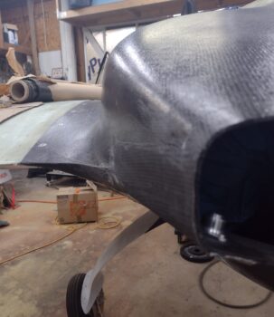
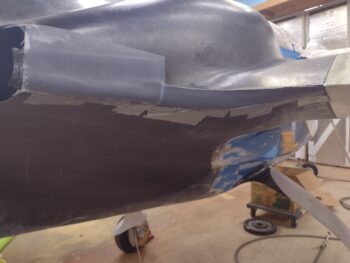
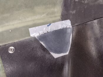
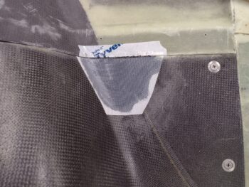
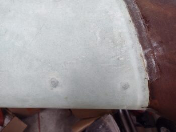
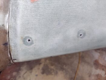
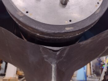
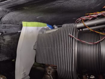
I then grabbed these shots of the top center aft end of the bottom cowling.  You can see the dimple on the right side in the first pic… that snuck in on me as it cured I’m guessing because it looked very symmetrical to me when I laid it up.  Oh, well.

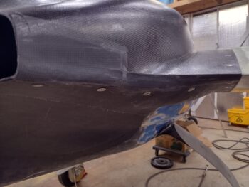
The second pic shows a piece of tape I placed to represent about how I’m going to round off this back end.  I will then lop off all the rest of the top center CF and rebuild it to make it look presentable.

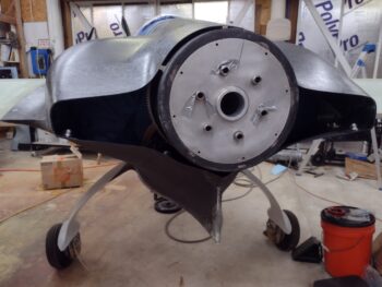
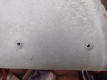
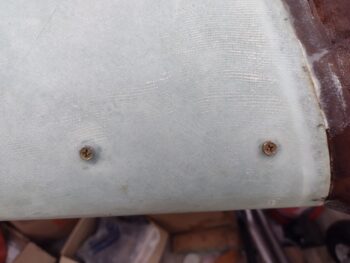
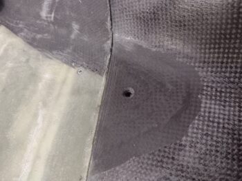
As I started in my efforts to rework the top center of the bottom cowling, I needed to remove the top cowling first.  I figured I would go ahead and get the countersinks drilled to allow me to use CS screws in the 2 screw positions on the top cowling.

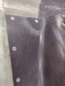
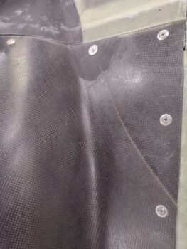
Here we have the drilled countersunk screw hole on the left side, with the right side looking the same.  My 3 plies of CF apparently did the trick since you might note that the countersink does NOT go all the way to the inside of the cowling (i.e. making the screw hole bigger than it should be for a #10 screw).

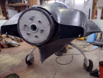
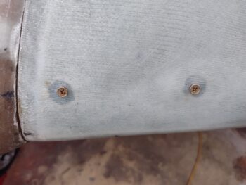
I then spent a few minutes rifling through my Tinnerman-style washers to find the good SS ones… and then threaded in the CS screws.  They look great in my opinion and I have to again thank my buddy Dave B. for a well-deserved nudge!

Here’s where my plan went south.  Remember, I’m having comms with Steve Beert, Marco, Mike Toomey, et al, regarding baffles and baffle seals.  My curiosity got the best of me and I drug some baffle pieces out to the shop.

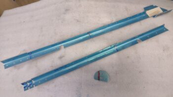
I didn’t get pics of them, but I also trimmed down the left and right aft VAN’s baffle segments that I plan to use to create the shelf segment of the aft shelf & skirt.

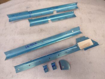
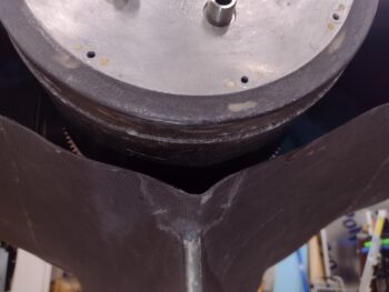
Here we have the VAN’s left side baffle segments in place.  You can clearly see that they are much too tall to fit under the cowling and obviously will need trimmed down a good bit.  That being said, it’s nice to have baffles that without a single cut slide right into place onto the cylinders… hoo-ah!

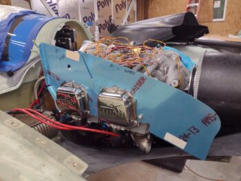
To get an actual bead on the height required for my side baffles, I then removed the VAN’s baffles and cut screw holes in Mike Beasley’s “Beasley Baffles” poster board cutouts I have… remember, these things went through both a hurricane and a tornado, so they are a little bit beat up and discolored.  BUT, they are working for my purposes here (the right side baffle templates were ruined by excessive water damage).

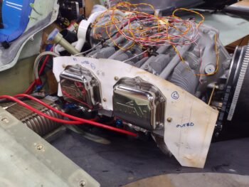
Using the Long-EZ plans as a guide, I’m looking for 1/2″ to 3/4″ perimeter gaps between baffles and top cowling, except at the cylinders which will be around a 3/4 to 1″ gap.  With that in mind, I peeked up into the aft cowl opening to check out the the cowl gaps with Mike’s “Beasley Baffles” in place [Point of note: Mike has the Task style cowlings, which is considerably different than my Melvill cowlings].

I also peeked at the baffle template mockups through the oil check door, and could tell they were a little short on the aft two-thirds across the left side, and considerable too short on the front third.  I added some tape and after a couple of iterations was able to get the approximate 3/4″ to 1″ gap I was looking for.

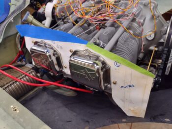
Here’s another shot from the aft end with the added and trimmed tape in place.

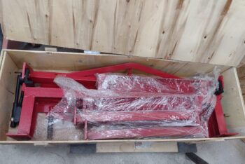
With my initial baffling mockups in the bag, and my education on baffles increased exponentially throughout the day, I then did one more quick task before calling it a night… I cracked open the case, a virtual treasure chest if you will, that has my long-ago bought metal brake inside.

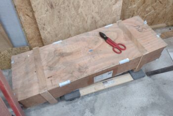
I bought the metal brake to use for any metal bending I might need to do on any project, but specifically for bending aluminum baffle pieces for this bird.  I did a quick inventory, grabbed the instruction manual, and then headed into the house.

Tomorrow I do plan on getting back to working the top center lip of the bottom cowl, but I have to say both yesterday and today were very motivational in learning just how doable these baffles are.  Pressing forward!

Chapter 23 – Baffling Baffles!

Today was all about baffles.  As I’m letting the cowling side interfaces get a good multi-day cure, and it being a grey rainy day, I hunkered down and just did a ton of research and planning.

The first half of the day was mainly about the inter-cylinder baffles.  I very likely have access to some molds that will allow me to make all the inter-cylinder baffles out of carbon fiber… not too shabby.

But then comes a requirement for hi-temp epoxy.  It’s not mandatory, and I even found a forum post where Klaus thinks MGS 285 with slow hardener would fit the bill.  But I actually may not have enough MGS 285 to do a project like making a whole set of inter-cylinder baffles.

After talking to Steve Beert and Mike Beasley, and doing a ton more research, I finally pulled the trigger on some HTR-212 high temp epoxy from ACS.  While it is higher temp than MGS 285, it’s not as hi-temp as the Max HTE that Steve recommended.  However, one major advantage that the HTR has is that doesn’t have to be post cured on the mold like Max HTE does.

So as I transitioned into assessing my entire baffle requirements as a whole, I went back and reread the build plans (yes, it is for an O-235), pinged Marco with some questions on his bird (he responded at one point with a link to a great post that covered his baffles), reread Mike Melvill’s cowling install instructions —which includes pics and diagrams regarding his baffles, and did a myriad of searches in the old CSA articles and the newer COBA ones as well.

I then started constructing my plan.  I had brought all the parts from my VAN’s baffle kit into my living room last night (I can do that cuz I’m not married!) and separated them into categories.  Today I then took different parts out to the shop to physically and visually assess how they would fit into my cowls and on my engine.

One of the complaints that I hear Canardians state about the VAN’s baffle kit is that you essentially get 3/4 of a kit: the forward (accessory side), the left and the right.  Since our aft end is their intake end, supposedly the kit doesn’t work for that side and you have to build it all from scratch.

But I disagree.

Mainly because I had an Ace up my sleeve: a cut out version of Mike Beasley’s “Beasley Baffles.”  Using Mike Beasley’s segments for the aft end, where the aft “skirt” drops down to create the aft wall with openings for the alternator, starter, and exhaust pipes (and oil cooler too if you have it on the back baffle wall), I was able to identify how to modify the front inlet segments of the VAN’s baffles to create the top “shelf” of this “skirt” with flanges to mount the lower vertical wall to…

Now, it won’t be as sexy as Mike Toomey’s one-piece aft baffle skirt/wall pictured above, but it will serve the purpose with the least amount of effort, materials and expense to get these baffles done.  Moreover, it allows me to keep the VAN’s cross section parts that butt up to the aft of the cylinders on each side to then be able to have ready available mounting holes for the side pieces, brackets, etc.

After going through the VAN’s install manual page by page, assessing literally every piece to decide whether I could use it or not (I would say I “tossed” about a quarter of the kit), I then got to work on getting some of the parts that needed disassembly (aka cut apart) knocked out.

Here are two 90° extrusions that are actually 3-4 parts apiece after they’re cut up.  Also in the pic is a reinforcement plate for a baffle-securing bolt hole.

After I took the Dremel Tool to the extrusions, I was left with all my usable pieces in the bottom of the pic, while the 2 pieces at the top are excess.

When I get to it I’ll point it out, but there is literally an included bracket in the VANs kit that is used to hold up an oil cooler if you choose to mount it in the aft wall (our forward wall) of the baffles.  Well, this bracket —with a bit of trimming— will work perfectly as a bracket Mike Melvill drew up in his cowling install manual to make up for the baffles.  More significant work avoided! <wink>

Ok, although I didn’t get a lot of physical work done in the shop today, I think I have a pretty darn good grasp on my baffle plan.  And with that folks, I’m calling it a night!

Chapter 23 – Cowl side cleanup

I started off today by pulling the peel ply on the right side ‘final’ CF layup that created the top cowling skin over the inter-cowl-connecting flange.

I then pulled the top cowling, cleaned up the edges of the flanges and the new top cowl added “skins” (both sides) as well as pulled the tape and cleaned up the bottom cowl edges.

I also trimmed and sanded the added CF plies to the top cowl screw holes and redrilled those holes out.

I then remounted the top cowl to check out my interface seam between top and bottom cowling on each side.  Not bad and all… and very workable with a little blemish-hiding micro!

I realize that over the past couple weeks I haven’t really gotten an all-encompassing aft end shot.  I did a good little bit of cleanup around the strakes and wing tops to get a more presentable shot here, clearly with the spinner temporarily in place.  Yes, the spinner is in focus and the cowl opening sides are not, but you can certainly make out the size and shape of the aft cowl openings.  The outer edges of the openings ended up being a hair over 2.5″ high.

Here we have a couple of shots, from both left and right angles, showing the aft cowling opening, the new aft sides and a bit of the interface between top and bottom cowlings.

I’m leaving the ~5/16″ spacers in place between the top cowling and spinner for a good week minimum as the final curing of the side CF takes place to ensure I maintain that gap.  I’ll also be glassing in a cowl stiffener across the aft inside end of the bottom cowling which should not only help keep the newly made outer panels of the lower cowling stiffer, but also help keep the top cowling in its position as well.

These shots focus more on just the aft opening of the cowling, with the interfacing sides of the cowlings.  My next near-final tweak on the cowling will be re-doing the top center lip on the bottom cowling, just below the spinner flow guide, to make it rounder and more symmetrical.

I spent a good half hour sanding around the vinyl letters I placed on the upper inside panel of the aft nose/avionics cover.  After a good cleanup I then hit it with 2 light coats of primer, followed by 2 light coats of white paint.

I’ll let it cure for a couple of days, tape off my checkerboard pattern and then hit it again with 2 coats of white.  I’ll then pull the checkerboard squares off, cover the white squares and then shoot the black paint.

I’ve also been doing a rather deep dive on my engine baffles.  As a reminder, I have the VANs baffle kit on hand for an O-320 motor.  These baffles take care of the front  (accessory case), left, and right sides, but the prop/exit side will have to be built from scratch.  Also, I’m fairly certain that I’m going to be able to get my hands on some molds for the interior baffles to make them out of CF.  More on that.

And yes, I do have mental plans on how to button up the plane to start sanding and micro-finishing the top areas to finish for paint.

But one step at a time in finishing this bird up!

Chapter 23 – Cowl interfaces glassed

This morning I started off by pulling the peel ply from the top cowl left/bottom/aft side’s “final” CF layup.  Of course with caveats that I may do a small filler layup in a spot or few.  I then cleaned up the edges and small bits of overhanging CF.  Again, I’ll need to lean on micro to completely clean up the surface, but it looks really good.

Since the pic above seems to make the side of the big aft cowl opening look like it slants outward —just perspective— I grabbed this shot below to show that isn’t the case.

I then pulled the peel ply of the right side’s 3-ply CF layup, and cleaned it up for another round of CF.

I then assessed the surface, measured, made templates and cut out CF plies for the final layup on this right side.

Then, again using MGS 285, I laid up the puzzle that is the final layup on this right side… with the same caveats as the left side of course!

I then peel plied the layup.

I found my next task laced with a bit of irony.  My reasoning for installing a screw on each side of the leading edge of the top and bottom cowlings is based on a recommendation from Wayne Blackler, who himself had lost CAMLOCs due to the pressure from the oncoming air.  Having armpit scoops on the bottom cowling especially, and know that the air flowing over the curved wing shape of top cowling wants to pull the cowlings out, I thought it a good idea to follow Wayne’s advice.  That was Round 1 over 10 years ago.

Circle back around to these screws, and Dave Berenholtz was having a recent conversation with Wayne about mounting depths for various screws.  Wayne noted to Dave that going into composite material it’s 66.7%, so for CF it needs to be 3/2 X countersink depth.  The example Dave gave is that a 3/16″ MS24693 screw has 0.080″ countersink depth, therefore you need 0.120″ thick CF.  The main issue is that the hole grows into a big dish and alignment gets sacrificed.

The thickness of my cowling varies quite along the front edge.  At the screw holes positions one side is right at about 0.070″ and the other is around 0.074″.  I told Dave I’d probably just use button heads at these points to get this bird in the air.  That’s when Dave got ruthless, using intense peer pressure tactics to let me know if I did that, all the other Long-EZ owners would point, sneer and laugh at my bird for looking so dumb… (hahaha! Just kidding!) He did note that it’s better to do a little work now and use countersunk screws for it to look classy vs screws that look like an afterthought.
Big sigh….  Yep, he’s right.

But I did compromise in only adding 3 more plies.  At 0.011″ thick per ply I’m well over 0.1″ on each side now, and to minimize a thicker bump requiring even more micro fill than I’ll require on this bird, I stuck with that configuration: as you see below. If I find the amount of meat is lacking, then I’ll throw another ply over all of these overlapping further onto the cowling.

Here we have the 3 plies CF for the left side screw hole, which I then wetted out.  Yes, I know the layup is a bit wet, as I used the peel ply to soak up the excess epoxy.

I then did the same thing on the left side.  Here are both sides with the 3 plies CF laid up and peel plied.

I then spent the next hour for arts n crafts… gotta have some creativity on these birds!  I used Jess’s Cricut that she has at my house to make up another set of vinyl letters (just like the landing brake) and then spent a good little bit centering them and getting them onto the curved inside surface of the aft nose/avionics cover.  I was going to do a round of painting, but it was getting later in the evening and I need to do a decent bit of sanding and prep before the next round of paint goes on… so I figured starting tomorrow that I would do a bit on this each day until this sideline project is finished.

Instead of doing the next round of painting on the aft nose/avionics cover, I decided to knock out another small task on my list: opening up the buried threaded inserts on the leading edge of each wing for the baggage pods.  I’ll note that all the other threaded screw inserts on the bottom of the wings are open and ready for the baggage pods (I know, a bit out of order but I wanted to install those while the wings were inverted).

Opening up access to the threaded inserts here was really like opening up a time capsule.  You see, early on in my build I learned a great hack from Marco on filling threaded inserts, platenuts, rivnuts, etc. with plastic Saran wrap to keep the epoxy, micro or flox out of the threads.  And since that little hack worked such a treat, I’ve been doing it ever since.  So whenever I drill into a threaded insert, I expect the drill bit to grab a bunch of plastic wrap and to pull a big plug of it out.  It’s satisfying in the same way pulling peel ply is!

But these were finished before I learned that hack.  When I drilled the holes out of the overlying glass, I saw nothing but threads… what the?  Then I remembered I just used a small roundel of duct tape over the hole to protect the threads.  Apparently that worked a treat as well…  the crazy little things in these builds.

I then rounded up some test bolt/screws to thread into the inserts to ensure all was good… perfect.  No issues whatsoever.  Task complete!

Tomorrow my goal is to start back on the exhaust pipe clearance assessment and working the bottom cowling baffles/ramps.  In addition I’ll make another attempt to contact my MIA exhaust pipe welder, James.  I’ll also note that I reviewed the install manual for the VAN’s O-320 engine baffle kit I have and will most likely start playing around with that a bit as well.  Moving forward . . .

Chapter 23 – Cowls: Closing In

I started off this morning by pulling the peel ply from the “3-ply” CF layup on the bottom aft edge of the top cowling.

I called it a 3-ply layup to make it simple in my last post, but actually only the front half of this layup, about where the sharp trailing edge terminates near the middle, has 3 full plies of CF.  From that point aft there is only one ply that is fairly narrow, borders the grey tape and terminates at nearly a point at the aft end of the cowling.  This is due to the narrow CF piece I added being fairly thin.  That being said, there is room for one more ply to fill this remaining lower area at the aft end of the cowling.

Again, this isn’t my preferred style of cowling closeout, but I realize that A) there has to be space allowed for the exhaust pipes —and that is THE reason you have this bulbous lower cowling meeting up with the top cowling TE; and B) not only is this how Mike Melvill designed it, but going with the design seemed to be the best path of least resistance in getting these cowling installs finished.  With that being said, I’ll remind everyone that this is an iterative process… mainly because I’m not only constructing the lower lip of the top cowling, but matching edge thicknesses between top and bottom cowlings as well.

I then prepped the surface on the right bottom side of the top cowling.  I cut another filler piece of Lantor Soric and applied it in about the same area as on the left side. I also had a narrow (less than 1/2″) one-ply CF filler piece for the dip at the seam of the aft and middle flange layups.

With all the prerequisite tasks out of the way, I laid up 3 plies of CF butting up to the edge of the bottom cowling on the lower side (gray tape) and along the top cowling TE on the front half and the top cowl original edge on the aft half.

I then peel plied the layup.  I’ll note that I used MGS 285 epoxy on this layup.

I already had a loose plan of how to layup the final plies of CF on the left bottom side of the top cowl, but that was accelerated a bit since I had some MGS 285 leftover in the cup from the right side (par usual… sigh).

My first ply on was what I discussed above, a very narrow wedge shape at the aft 8″ of the cowl, butting up against the gray tape edge and filling the area that only got one ply on the first go around.  I then added a ply that butted up against the aft end of the bump created by the embedded Lantor Soric piece.  This ply also butted up against the gray tape seam but was about 1/2″ shy of the sharp TE, wrapping around & upward just aft of where the TE dives into the vertical wall of the top cowl —which is clearly where the aft vertical segment begins.  This ply went a good inch up above the top seam of the small added CF strip, overlapping onto the original top cowl skin.

Except for about 3″ on the very outboard side where this bottom side lip meets the wing root edge (full width CF in this area), none of the remaining plies touched the bottom side TE… yet all abutted/terminated at the gray tape seam and came up from there in stepped fashion.   I didn’t need to add any more to the TE since it’s already way off balance with a low flat profile on the top, and a fat bulbous profile on the bottom.  My main goal this round was to simply add thickness to the bottom edge at the seam with the bottom cowl edge to match elevation.

All above ply descriptors aside, the bottom line is that I met my design objective of having 5 CF plies on the bottom edge of the top cowl lower side meeting up at the seam with the 5-ply CF thick bottom cowl edge.

I then peel plied the left side round #2 (and very possibly final) CF layup.

Tomorrow my plan is to knock out round 2 on the right side.  I may very well end up adding a ply or two of CF on the left side as filler, but beyond that it is very close to being complete.  At some point I will have to hand off the final top cowl bottom side “makeover” to Mr. Micro and let him do his job too!

Pressing forward!

Chapter 23 – All CAMLOCs on deck!

I started off this morning by pulling the peel ply off the cured 2-ply CF layups on the inside of the top cowling left and right CAMLOC flanges.  I then cleaned up the layups and trimmed the overhanging CF on the edges.

I then mounted the top cowling in place and drilled the very aft and the #2 CAMLOC positions on both sides.  I then removed the top cowling and installed these CAMLOC receptacles.

I will note that my planned types of CAMLOCs (technically SkyBolt used here) changed significantly since the aluminum rigid, adjustable SK215-4 receptacle flanges are much thicker than the SS or the SK245-4 receptacles and I don’t have longer CS rivets on hand.  I had planned on using one stainless steel + 3 aluminum SK215-4 receptacles, but ended up using only 2x SK215-4 + 2x (completely unplanned) SK245-4 receptacles… again, all due to the thickness of the SK215-4 flanges.

After the first pairs of CAMLOC receptacles were installed on the flanges, I then remounted the top cowling and drilled out the last 4 CAMLOC positions (2 each side).  I then repeated the process above by removing the cowling and installing the CAMLOC receptacles on the 5-ply CF flanges.

I then installed the last pair of CAMLOC studs on each side.  With that task completed, ALL my cowling CAMLOCs (and the plane for that matter) are now installed.

Here’s the left side 4 CAMLOCs installed.

And here’s the right side CAMLOCs installed.  The gray tape is prep for the exterior lower edge layups on the top cowl…

Which I started on the left side.  Since I have a decent gap on about the first 6-8″ of the seam between the top cowl flange and the bottom cowl skin, I thought a good bit on how to fill that gap.  Do I use just a bunch of plies of CF?  Should I use foam to keep it light?  Then I remembered a neat little material that I have on-hand… an ace up the sleeve if you will: 2mm (0.078″) Lantor Soric material.  It adds thickness but is very lightweight.

As you can see, I figured out where I needed some filler the most and cut out a piece of the Lantor Soric.  I also made templates of the top cowl lower edge here (using my forms I used during the previous flange layups) and cut out 3 plies of CF, which I then pre-pregged.  I then cut some peel ply as well.

Here I’ve wetted out the top cowl left side lower edge with MGS 285 as well as the Lantor Soric filler piece.  If you look closely, just under the yellow piece of tape, there is a small gap filler ply of CF as well.

I then wet out the pre-pregged 3-ply CF setup and laid up the plies of CF.

And finished off the layup with some peel ply.

I’ll point out that this is simply round one of the lower edge fill.  Since the bottom cowl edge is 5 plies thick, tomorrow I plan on adding another 2-3 CF plies to this layup to create a nice transition and flow at the seam of the top and bottom cowlings.

Clearly I didn’t get to the right side, which I of course plan to do tomorrow.  But with a good layup in hand and curing, I called it a night!

Chapter 23 – Top cowl flange fin

I started off this morning by pulling the tape from the cured 3-ply CF flange layups on both the left and right outboard sides of the cowlings.  These layups not only create the flange to secure the top and bottom cowlings together, but are also the underlayment for the elevation layups that will bring the top cowling bottom side (below the TE) level and even with the edge of the bottom cowling.

If you look closely, on the very outboard side of the cardboard forms, just adjacent to the wings, you’ll see a narrow “L” shaped strip of remaining wing lower flange.  This is a stop for the yet-to-be-made elevation/”filler skin” layups to press up against to help control air leakage from the cowlings [trimming the cardboard forms to expose the “L” edges was one of the mods I had to make early yesterday before I started the layups].

Here we have the left side cardboard form, where you can see the taped interior that was pressed up against the exterior of the 3-ply CF layup… replete with peel ply.

And on the right side I’ve removed the form to simply expose the laid up and peel plied 3-ply CF.  Again, note the “L” shaped edges of the lower wing flange.

As I mentioned in a recent blog post, I wasn’t overly happy with having to move my aft wing-edge CAMLOC forward.  I also wasn’t happy with how close the outboard top/bottom cowl CAMLOC was to this wing CAMLOC, which was around 3″… while the other top/bottom CAMLOCs were spaced at a little under 5″ between them.

Well, I figured now was a good time to remedy all that before I moved any further in my cowling interface completion efforts.  After a bunch of measurements I moved all the CAMLOC positions aft, starting with the very aft CAMLOC which I moved 1/2″ closer to the big opening.  All the other spacings were lessened by about 5/16″ to 4.5″ on center.  This put the gap between the bottom aft wing CAMLOC and the outboard top/bottom cowl CAMLOC at 4.2″.  Very acceptable.

I then prepped for the next phase of the top/bottom cowl interface: full length 2-ply CF tapes on the inside of the existing 3-ply flanges.  Obviously this would give me a total of 5 plies of CF for the flange while also connecting the 3 separate flanges (the aft 2 are connected by an overlapping ply of CF) layups together.

Here’s that layup on the left side.

I did add 1/32″ G10 reinforcements to the 2 center CAMLOC positions with wet flox on the face and dry micro around the edges.  I had actually wanted the very outboard CAMLOC position to get the reinforcement and then skip the next position, but the flatness of the flange would have made it too much of a pain to add into the layup, so I moved it to the next position.  For the first and last CAMLOC positions I simply added an extra patch of CF for reinforcement.

Finally, since the aft 3 CAMLOC receptacles on each side will be aluminum, I added a final patch of BID on the top of these CAMLOC positions to ensure no galvanic or other funky reactions take place over the life of this bird.

Here’s the right side full length 2-ply CF tape layup.  As for dimensions my first ply in was 3.5″ wide (to overlap just a bit onto the original cowl structure) while the second and final ply was 2.5″ wide (to overlap onto the gap layup).  Clearly I then peel plied the layups… with all the scrap peel ply I could find (cleaning house as this project nears the end!).

One final note on these layups is that I used MGS 285 here.  I wanted to add in MGS to the mix here on this flange for a little extra oomph in strength.

I then called it a night and left these layups to cure overnight.

Chapter 23 – Cowl gap closeout

Well, once again I was met by a giant creature wanting to help out with the build (all except the squirrels and field rats… they tear the place up!).  As you can see I had a giant Dragonfly hanging out on the door wanting in.  Most likely because the weather has been much cooler lately. He wanted some of that warmer shop air!

As I pondered on my upcoming layups last night and this morning, I realized that I had to do some tweaking prior to knocking out these layups.  Since I had to pull the top cowling off to do these pre-layup mods, I grabbed these shots of the protective tape on the bottom cowling, the taped thin cardboard forms (taped to the cowl TE) and the taped up wing flanges.

I actually wet out the pre-pregged 3-ply CF setups, then wet out the lower/outer peel ply on the tape, and then laid up both left & right cowl sides with CF before ever putting the top cowl back on.  In fact, I applied and wetted out the inside peel ply on the CF layup before the top cowl went back on.

I then rolled the layup over onto itself going forward and mounted the top cowl.  I then reached up into the cowling and pushed and prodded the layups into the position I wanted.

Since I hadn’t yet secured the taped cardboard form in place yet, I could visually see the gap part of the layup.  The area of the layup on the bottom cowl I had pretty much finished prior to the cowl going on.  I could feel the layup on the underside of the top cowling as well.

I then visually ensured the gap area looked good and then taped the form into place. That’s what you see in the pics below.

The one little snag I had is that the front edge of the middle third transition flange layup has a slight curve to it, and my form wanted to sit flat with the edge a straight line (the ‘ol shortest distance from point a to point b thing!).  Since there is no overlap from this layup onto the middle one, to correct the non-curve issue I simply slid a pointed razor blade into the seam and pulled the layup edge into position.  I then taped the razor blade in place at the correct angle and left the layup to cure (note the black duct tape).

On the right side I had a bit of the same issue, but a double ply of Gorilla duct tape was enough to keep the new straight layup in line with the “old” middle flange edge.

These layups weren’t necessarily difficult, just tedious with constant prep steps and checks to ensure all was good since I was flying only by feel on a good bit of it.  I did double check my work with a work light and a mirror, and thankfully it all looked pretty good.

Back in the house, as I was making dinner, I went into arts ‘n craft mode by using a glue stick to attach the cut off top portions of the armpit inlet baffle (“ramp”) templates to a blank piece of printer paper.  I then drew a 1/2″ extension on all of them (the tab to rivet to the lower ramp pieces) and made a photocopy of them on my printer.

I then cut out the new extended versions of the top ramp portions to use to create the aluminum top segments of the ramps.  I will verify each one’s shape though with my engine configuration before I do any cutouts of aluminum.

And with that, I called it a night.  Tomorrow my goal will be to get the 2-ply CF tape laid up on the inside of the flanges to secure them together and create a 5-ply flange to mount the CAMLOC receptacles to.

Chapter 23 – Cowls to wings

Besides pulling the peel ply off the cured middle “1/3” transition segment layups and then measuring and drilling a Cleco hole at the #3 CAMLOC position, today was all about planning and prepping for the final outboard layups… where the top cowling specifically interfaces with the wing trailing edge (TE).

I also trimmed the overhanging 3-ply CF flange layup at the aft opening as well.  I’m really liking how the flanges and the aft opening edges are looking.

Here’s the same shot on the right side. You can see I did the same thing here, with peel ply pulled, Cleco installed at CAMLOC #3 position, and aft opening CF trimmed.

As a rather significant (IMO) point of note, I’ll state that I prefer the style of top and bottom cowl interface where the two cowlings meet at the TE and are simply attached together, pretty much in line with how the plans show to do it.

However, that’s not how Mike Melvill designed these cowlings, and for me the difficulty in doing the plans method is the aft/inboard vertical element transition to the forward/outboard horizontal element (where the cowl meets the wing TE).

I know this pic below of Mike Melvill’s cowling isn’t super clear, but you can see the CAMLOCs along the top-to-bottom cowling interface.  Notice how the top cowling’s aft vertical “wall” wraps around the aft bottom corner with the CAMLOCs underneath.  Then notice the swoop (or smile) as there is a bottom lip on the top cowling, with the ENTIRE cowl TE belonging to the top cowl.  Again, ‘normally’ the TE is the point where the aft edges of the top and bottom cowlings meet.

Finally, note the junction where the wing TE meets the cowling TE.  Again, with the TE belonging completely to the top cowling, there is about an inch on the bottom side (still top cowl) that nestles in at the seam of top cowl, bottom cowl, wing root, and wing TE.

That seam is what I spent a good bit of time figuring out on my cowling configuration.  I will note that since I had to lower my bottom cowlings, I continued the bottom swoop/smile further outboard —and thus forward— than it looks like Mike Melvill did.  It’s hard to tell simply looking at this picture.

To allow for this wrap-around TE style and to facilitate EZ removal and installation of the top cowling, I needed to trim both the top and bottom wing cowling mounting flanges aft edges.  Here’s what that looks like on the left side where I marked up the flanges for trimming.

And after I trimmed the wing flanges on the left side.

As a testimony that this wrap-around TE configuration was NOT what I had planned on doing from the beginning, I had to move my very aft CAMLOC forward around 3/4″… which I installed during this time.  I know the CAMLOC receptacle isn’t in good focus, but if you look just aft of the mounted receptacle you can see the original Cleco hole which obviously would have been the center of the original install point.

And yes, all my CAMLOCs are pretty much equally spaced all around the cowling edges, except for this aft corner on each side.  My bottom aft wing CAMLOC is skooched forward, and the spacing between this CAMLOC and the first one on the top-to-bottom cowling flange will be a little tighter than the others as well.  If the plane flies, then at this point I honestly am beyond caring (that much!).

I then repeated the process on the right side.  Here you can see the hole for the receptacle, and also the original Cleco hole and even a slightly offset Sharpie circle where I was going to do a slight offset at some point.

I then trimmed the right wing top and bottom flanges and installed the bottom aft CAMLOC receptacle (that leaves 8 total CAMLOCs left to install on this bird!).

The amount of flange removed top and bottom, on both left and right wings, is about 1.4″.

I didn’t grab any further pics, but after I trimmed the wing flanges I remounted the cowlings and spent another couple of hours making up my taped cardboard forms just as I did for the middle third cowling interface flange layup.  I also made templates to cut all the CF and peel ply.  I then prepregged the CF, finalized the prep and had everything ready for the layups… it was late though and I didn’t want to kick off these tricky layups so late at night.

Now, I had actually written out my task sheet for these layups with the idea that I was going to use pour foam, shape it, and then lay up the CF edges.  The plan was VERY dynamic as I went about working the layups on these top/bottom cowling interfaces. I’m hoping and expecting that after these next two outboard layups the finicky-ness and trickiness of these layups lessens tenfold!

Pressing forward.

Chapter 23 – Armpit ramps glassed

I started off this morning by pulling the peel ply and razor trimming the cured BID securing the G10 reinforcement strips to the armpit intake air-directing ramps.  To be clear, these are the aft sides of the ramps.

And here is the front side of the ramps.  In both of these pics the ramps on the top are the left ones, and on the bottom the right ones.

After the 3-ply CF flange cured on the right side of the cowling, I measured the left side and found that it’s about 0.15″ shorter at the edge than on the right.  I slung a 2.5 lb. weight near the center of the bottom cowling and it was enough to get the bottom cowl on the left with the same side opening as the on the right.

I then laid up the 3-ply CF flange on the left aft “1/3” of the top/bottom cowling gap just like I did on the right side.

I then peel plied the layup on each side.  Now, since I wanted to knock out the middle flange layup on each side tonight, I used MGS with fast hardener here.

While the left side aft flange layup cured, I created a cardboard mold to act as the exterior top cowling skin while I laid up the middle transition area of the top/bottom cowling transition.  The main reason I used a taped mold here is I wanted the CF as close to the exterior skin as possible, especially right at the edge of the top cowling.  If I had eyeballed this as I did the aft flange, I don’t think it would have been as close to the edge as using the form.

Just like on the other flange layups, I peel plied both the inside and outside of the layup.

A few hours later I pulled the peel ply off the cured left side 3-ply CF aft flange layup, and here’s how it came out.  Not bad at all… I’m really happy with how this turned out as well.

Also note that before I separated the top and bottom cowlings to pull the tape and peel ply, I measured, marked and drilled holes for the securing Clecos at the CAMLOC positions.  In addition, the lime green tape on the bottom cowling is my trim line marking to take just a hair more off the bottom cowling outboard edge.

I then used the same mold (taped up cardboard) method on the left for the middle transition area as I did on the right side.

Here’s a shot of the left side middle 3-ply CF flange layup on the inside before I peel plied it.

I’ll note that on the aft 3-ply flange layup that the inside ply of CF was short an inch on the front side.  Conversely, on the middle 3-ply flange layup the inner CF ply was inch longer than the first 2 plies —on the aft side— to allow an overlap onto the aft flange.  Moreover, all the 3 flanges on each side will get a 2-ply CF tape that will run the entire length of the flanges on the inside to tie them all together into a single 5-ply flange.

All told tonight, that’s 4 out of 6 major layups completed on the top/bottom cowling interface.  Tomorrow I plan on knocking out the last 2 before jumping into the interconnecting and finishing layups to tie the two cowlings together.