Chapter 23 – Baffle Tidbits

Today I wanted to knock out a bunch of small little tasks remaining on the baffles to get those off the to-do plate.

Once again, some of these tasks involved a good little bit of both research and decision making, which are both time burners.

I’ll start by covering a couple of early on tasks that I didn’t get any pics of:  #1 was determining spacing and then drilling rivet holes in the front right corner where the front outboard baffle meets the front side (cylinder #4) baffle.  This corner is left essentially rivet hole free in case an RV builder wants the option of mounting the oil cooler on the front (their aft) baffle wall.  “Undocumented” task #2 was the final shaping & deburring of the top centerline crankcase bracket for the front baffle wall (again no pics).

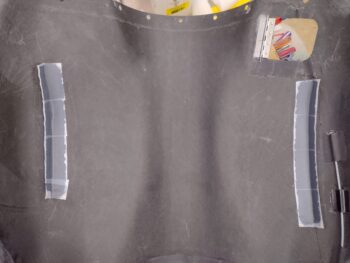
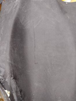
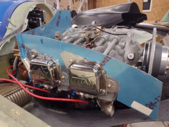
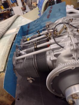
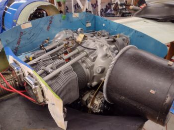
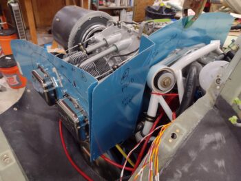
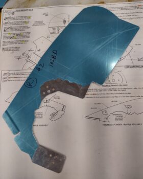
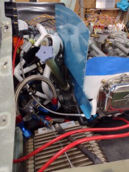
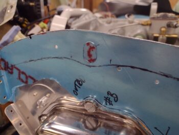
In keeping with my 1/2″ spacing between the aluminum side baffle walls and the top cowling, this left the decent-sized oval port —for spark plug wrench access— in place on the forward side baffle segments.  Clearly I needed to determine how I was going to seal up these ports, whether with the baffle seals themselves, or the hardware that was included in the VAN’s baffle kit [sidenote: the hardware to seal these ports in the kit is unusable… must have been leftover from a previous baffle design?].

I felt I needed to do some sideline research to see if there was any standards or guidance on how much of the baffle seal gets attached to the aluminum baffle wall, and what distance from the baffle edge should the mounting rivets be placed?  Well, after a good bit of looking in the plans, in both Tony Bingelis’ engine books, and online the only consistent standard I could find was to place the baffle seal securing rivets every 1-1/2″ to 2″…. all other install requirements were absent.  No joy there.

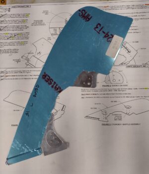
Moreover, I had to make a decision on whether to install and use the front side baffle reinforcement stiffeners that were included in the VAN’s kit.  Clearly with the shape of my top cowling, and thus my side baffles, a good portion of these stiffeners would have to be trimmed off.  Plus, how would they interface with the baffle sealing material? (clearly no issue on RVs since their side baffles are much taller than our pusher aircraft).  Finally, besides the designed U-notch to allow access to the spark plug port, how would these stiffeners work with accessing and using that port?

I spent a good hour going through different options on how to incorporate these stiffeners into the mix… I mean I have a row of rivet holes on the front side baffle segments, so I might as well use them if possible, eh?  In the meantime, based on my baffle configurations, I decided that I would mount the baffle seals overlapping onto the baffle walls by 0.9″ with the rivets equidistant from edge of baffle to lower edge of seal at 0.45″.

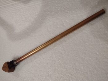
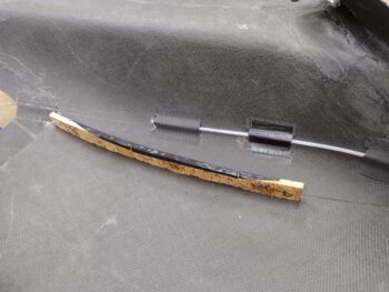
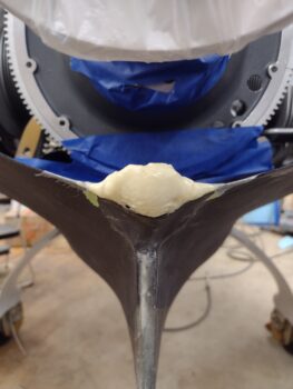
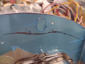
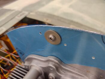
After discovering that the included VAN’s spark plug access port sealing hardware was simply not going to work, I started working on my own solution, with a bit more simplicity and elegance being a requirement.  Moreover, as I worked through various machinations and tested out different designs, I concluded that the VAN’s reinforcement stiffeners were a no-go and dumped them.  My best option came into view after I test fitted an AN970-3 wide washer to see if that would cover the spark plug access port.  It did.

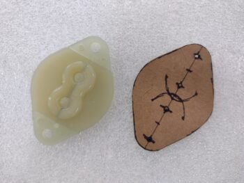
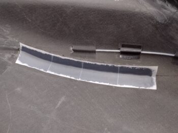
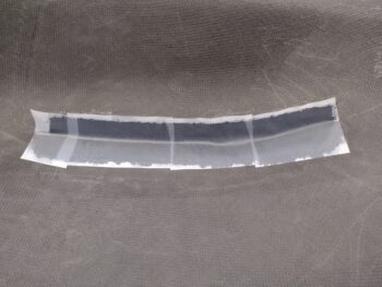
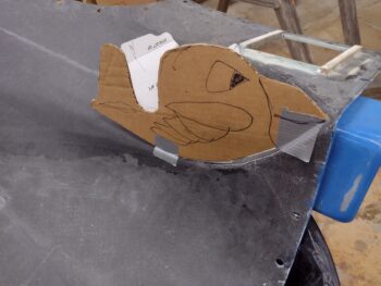
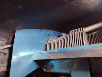
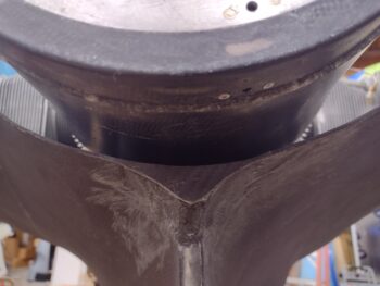
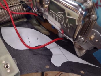
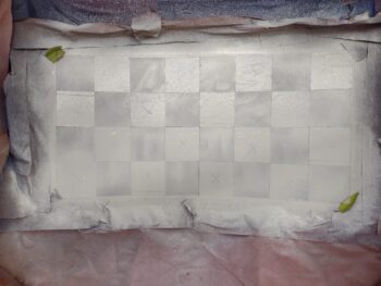
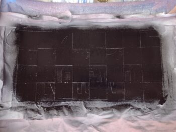
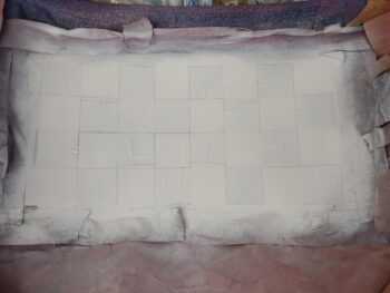
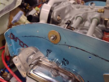
I then used some scrap baffle material to make up a couple of port filler pieces to simply fill in the middle area between the inside and outside AN970-3 washers: a glorified washer itself if you will, and here are the results.

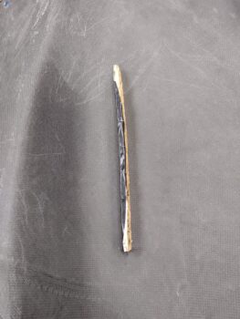
And also a closer shot of the size of this spark plug access port filler piece (sorry for the pic quality).

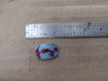
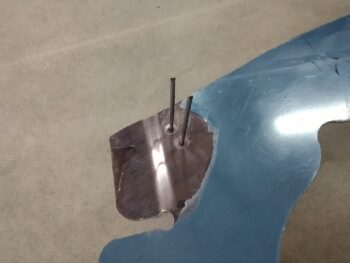
I then drilled a hole in the center of each filler piece to accept an AN3 sized bolt/screw.

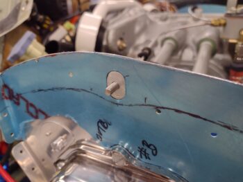
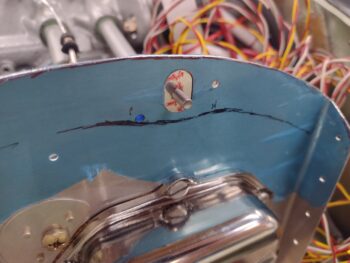
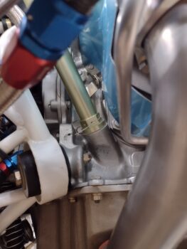
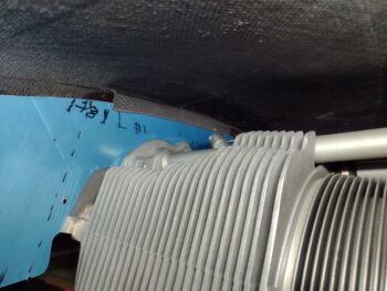
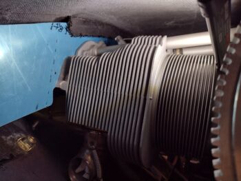
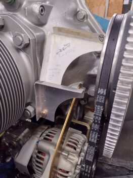
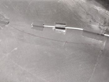
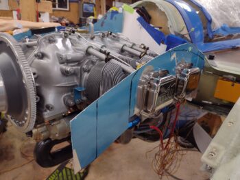
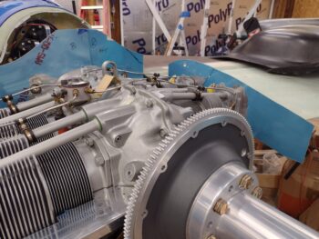
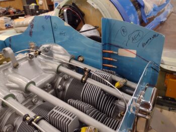
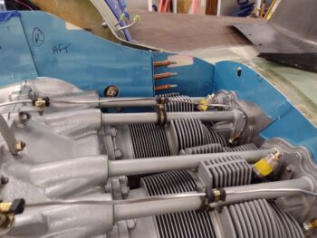
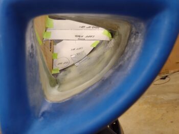
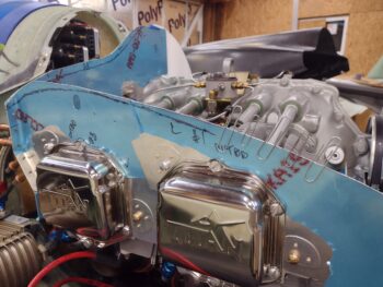
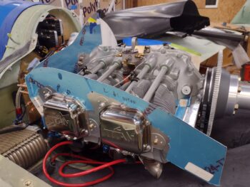
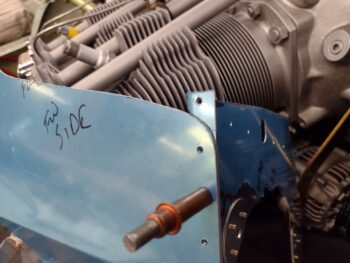
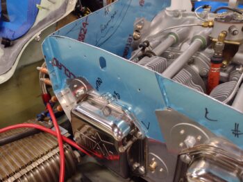
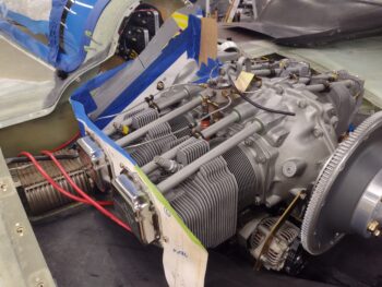
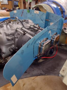
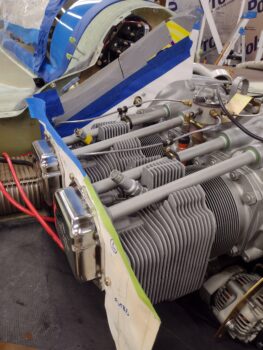
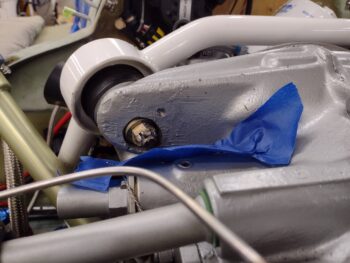
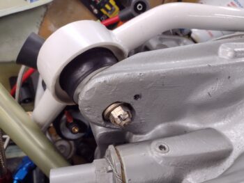
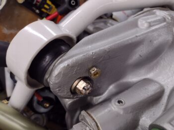
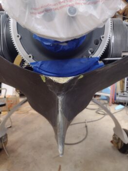
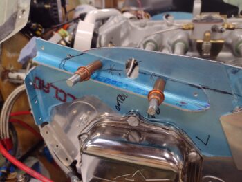
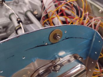
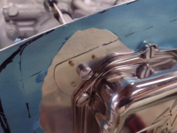
And then test fitted my new spark plug access port sealing hardware setup: an AN970-3 washer on each side, with the filler piece in the middle to support clamping pressure, and voila… EZ-PZ!  Here is a look at the inside…

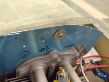
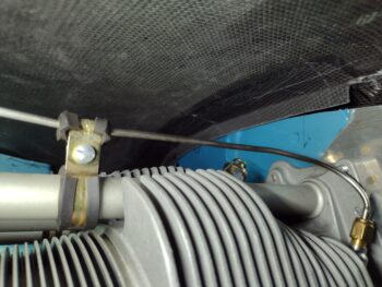
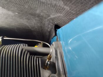
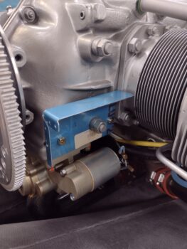
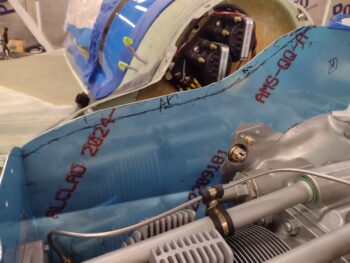
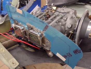
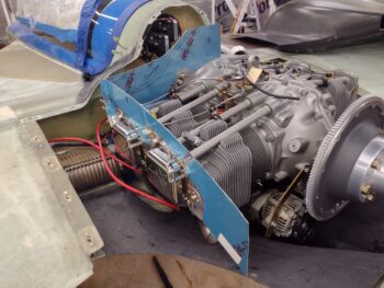
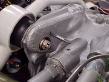
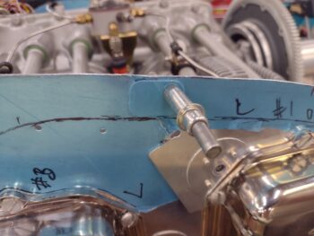
And the outside.  Most likely I’ll just simply make an access hole in the baffle seal material as well to allow me to remove these port seals whenever I need to install or remove a front spark plug (And yes, way too much time spent on these things… and even explaining it all.  But they’re done now!).

Moving on.

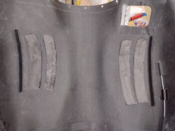
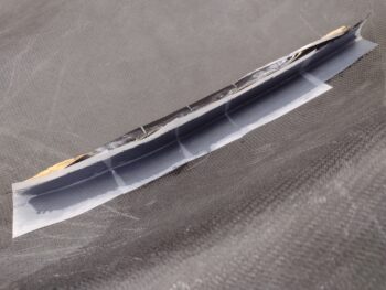
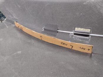
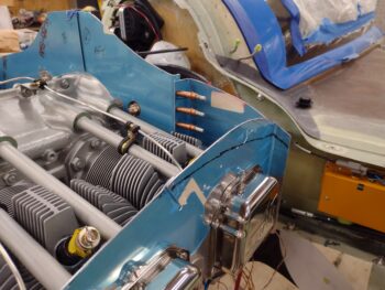
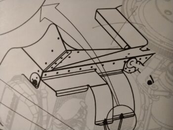
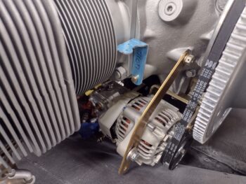
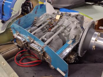
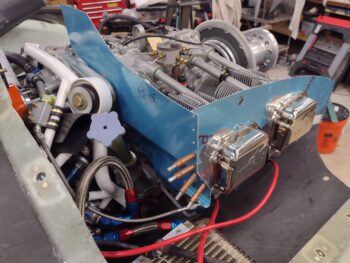
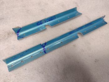
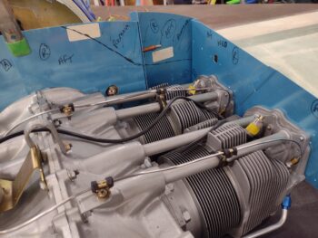
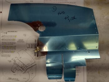
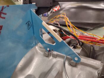
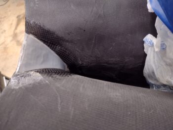
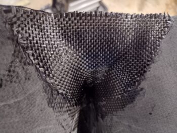
To help minimize vibration and chaffing, but still allow movement between the front and aft cylinder/baffle on each side, the VAN’s baffle kit includes these little side clips that get mounted on the outside of the seam between front and aft side baffle segments.

Normally, these are mounted just above the beginning of the split (lower) since there is more baffle material with sides higher in an RV installation.  For me, with much lower baffle side walls, I am using them both as a securing clip for the baffle seams, but also to secure the baffle seal in place since I don’t have enough room to mount it just on the aluminum surface.

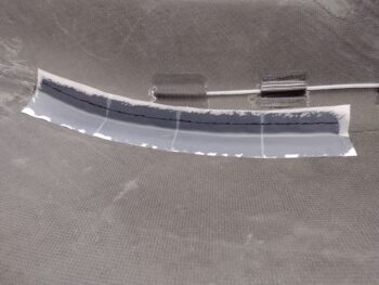
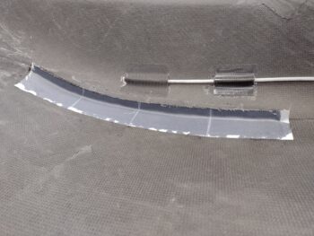
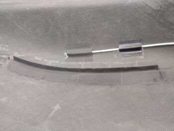
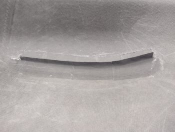
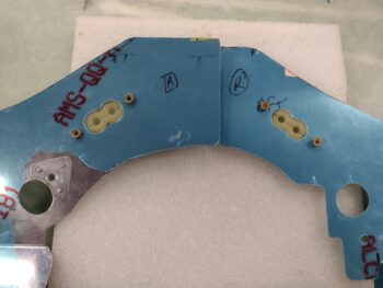
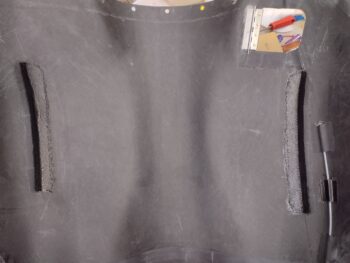
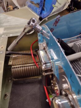
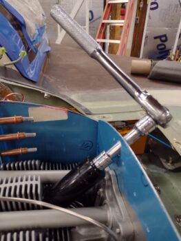
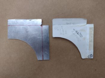
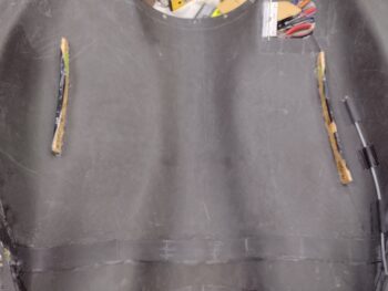
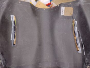
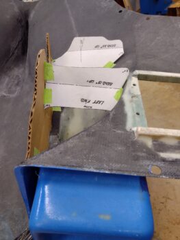
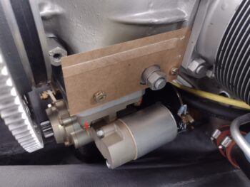
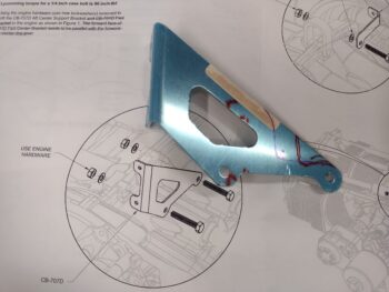
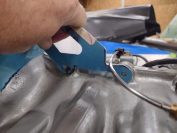
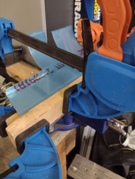
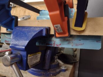
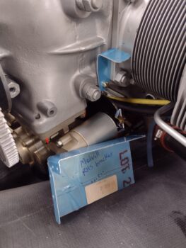
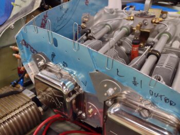
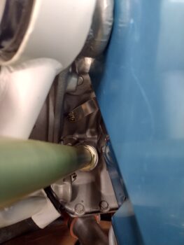
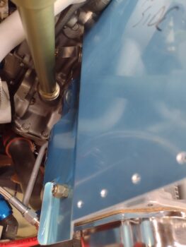
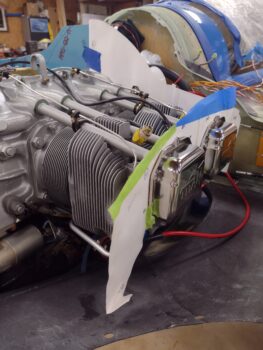
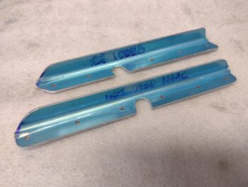
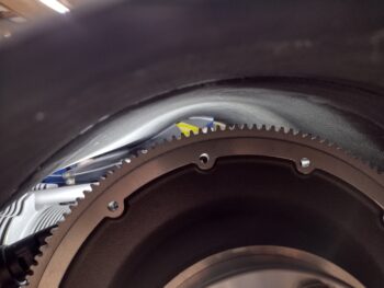
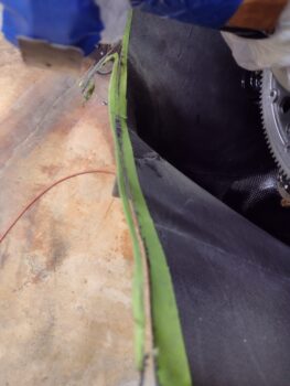
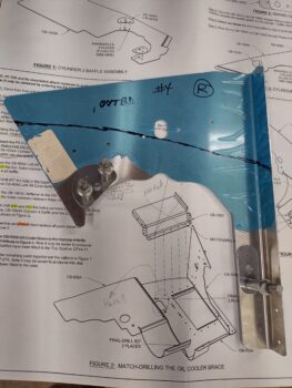
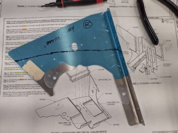
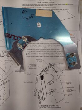
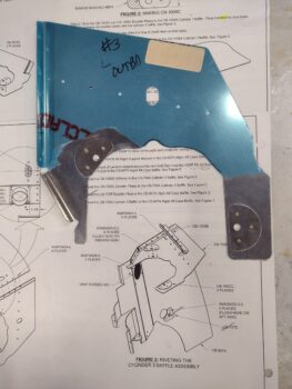
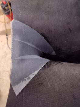
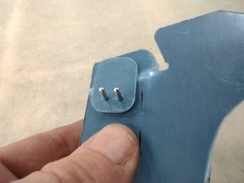
I drilled out #40 holes for the 2 securing rivets (pic 1), and then countersunk the holes on the inboard side of the baffle wall (pic 2).  The left side is shown.

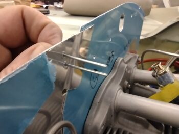
I then did the same thing on the right side.  Clearly these clips won’t get installed until the baffle seals are installed.

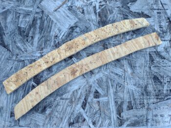
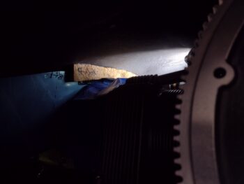
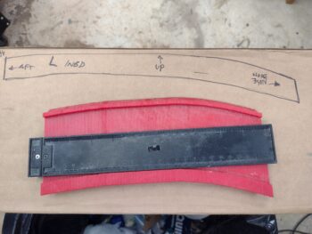
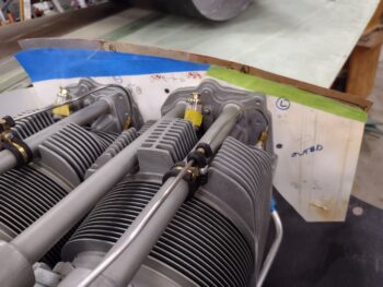
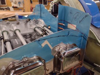
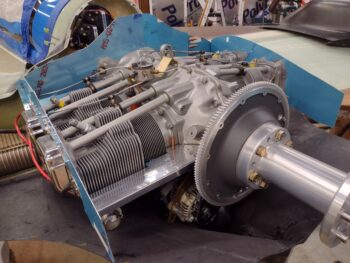
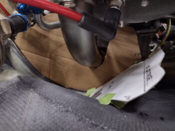
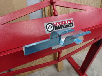
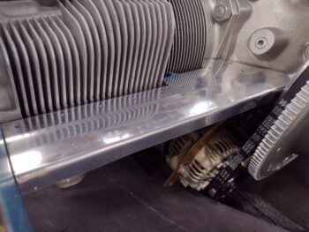
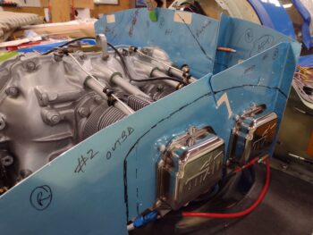
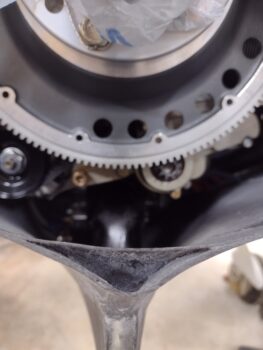
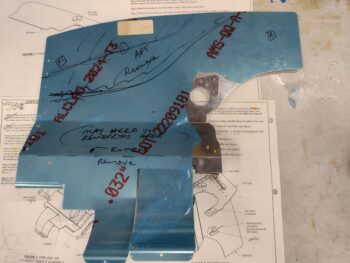
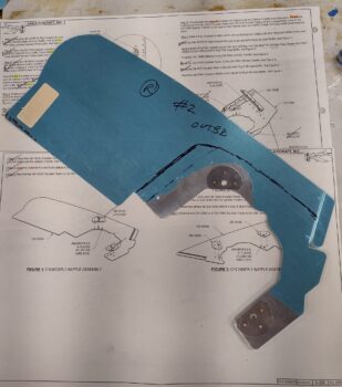
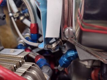
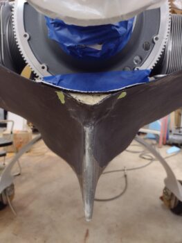
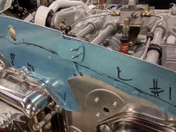
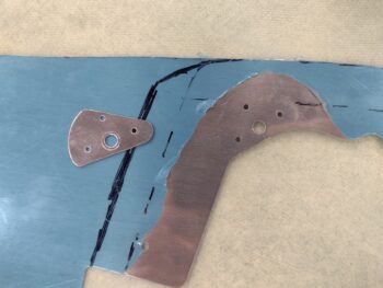
One minor issue that I ran across was my aft top doubler plate on the right side baffle at cylinder #2.  When I drew my line to denote the baffle seal attachment area on the right side baffle segments, that line crossed the top of the doubler.  Since I want to minimize any chances of air leaks with the baffle seals, I didn’t want any differences in elevation on the side wall… in short I needed to trim the top of the doubler off to allow the baffle seal material to sit as flat as possible.

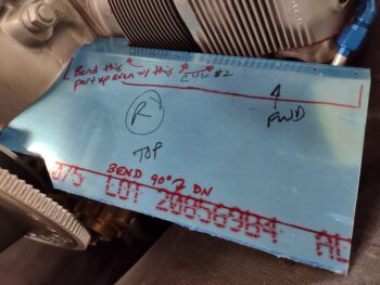
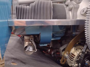
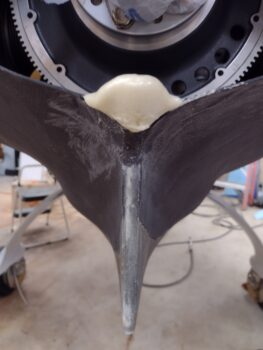
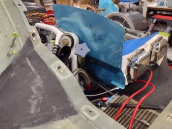
I drilled out the 3 rivets, then removed and trimmed the doubler . . .

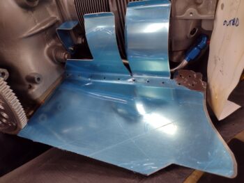
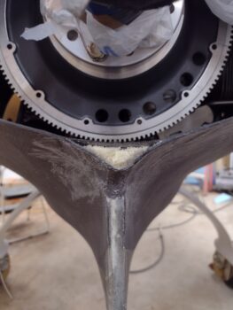
And then re-riveted the doubler in place.  Another minor, but needed, baffle task completed.

As yesterday, I had a bunch more tasks on my to-do list for today, but after a bit later dinner and some household stuff I needed to tend to, I never made it back out to the shop other than to lock it up.  With these niggling, low-hanging fruit baffle tasks done, tomorrow I plan to press forward with the final top cowl front baffle cross rib & stiffener as well as the bottom cowling inlet walls and ramps.

Chapter 23 – Baffles final trim…

On 3 sides: front, left and right…

But first, I started out today wanting to get a task knocked out that his been literally staring me in the face (sitting on my coffee table!) for a couple of months: the brazing of a 1/2″ brass tube into the brass 1/2-NPT 45° street elbow that will be my new oil heat oil sump fitting with standpipe to replace the massive 90° steel standpipe that is jamming up my SCEET tube underneath the engine.

A couple of months ago I had called literally about a dozen welders to see who could braze brass stuff… well, of course I started locally and moved out geographically.  The welder that I went to today is about 45 minutes from my house, so I figured I would go for a little drive this morning and get this thing done.  The good news is that they did it while I waited, after a discussion of exactly what my requirements were.  I wanted it brazed because A) I don’t have the Oxy-Acetylene torch kit to do it, and B) I’ve never done it before (if I had A than I would forge ahead and disregard B).

I told them exactly what it was for since their initial guess was that it was for fuel… fuel of course typically being cool.  Nope, this is for oil gents and it’s an oil fitting with standpipe inside an oil pan feeding an oil heat exchanger via a pump.  Of course the only thing I was purposefully vague on was that it was going into an airplane… any homebuilder knows how that conversation can turn out.

Well, they came out of the shop and asked me if the length was critical because they blew out the sidewall of the tube (I guess I’m not the only one who does stuff like that!).  I said no, I had plenty there.  They told me that the brazing rod they had was too big, and they had to find some smaller stuff.  Then the boss handed over my project to one of the minions, who peppered me with questions so we went over the specs and requirements again.  I was out front BS’ing with the owner and another customer… when, after over half an hour later out comes my pipe and street elbow joined as I had wanted.  However, it didn’t look like it was brazed, but rather soldered.  Hmmm?  I asked him if it was brazed or soldered, and he said it was a high temp solder since they didn’t have (or couldn’t locate) any smaller diameter brazing rod.  I responded that I was highly skeptical since I hadn’t heard of that, and he assured me it would meet my requirements… I thought maybe I had learned something new, but spoiler alert: it doesn’t meet my requirements.

When I got home I heated up my stove to 400° F and put the fitting/standpipe in there for almost an hour.  I pulled the combo out with oven mitts and could easily pull the joint apart.  Now, while it was baking I did some research on how hot it gets inside a Lycoming engine.  I couldn’t find any actual data on that, but Lycoming does state that the oil temp isn’t supposed to get over around 235° F, but I want my components to be able to withstand at least 350° F, with a safety margin… thus the 400º F.  I don’t know if I’m being too stringent, but I know that a brazed part and definitely a welded part would have no issues with my required temp tolerances.

So, alas, I will have to do this myself!

My first task out in the shop was to rewire the oil level tube to ensure it stays nice and snug in its place…

I then marked the top cowl rib baffles at just over 1/2″ high on the peel ply, which gave me some contrast to see my cut line.  Here’s the left side.

I then trimmed the rib baffles with my Fein saw.  Again, here’s the left side.

I also trimmed off each end, forward and aft, of the rib baffle on both the left and right sides.  I then cleaned up the cut edges with a sanding block to finish them off.  And here are my rib baffles, which I now consider merely an adjunct to my baffle setup.  As I told Mike Beasley, I’m pioneering a new “Hybrid Baffling System” … ha!

I then did a trial fit of the top cowling to see if I had any clearance issues with the rib baffles while setting the cowling into place, which I didn’t.  I then looked up inside to see how the rib baffles were positioned in relation to the actual baffles, and all looked good.  Again, I do have that minor kick-out inboard for the last aft few inches on the right side, but besides that they looked really good.

I then marked, removed, and did a final trim on all the baffle segments to dial in about a 1/2″ gap between baffle wall and inside top cowling all the way around.  The only segment that did not need trimming was the aft right baffle around cylinder #2.

Although I had a lot more on my to-do list to get done today than I actually did, one such task was to get the top spark plug wire baffle seals configured on the front baffle wall segments.  I made up a cardboard template and then assessed different access points for the Electroair spark plug wires to traverse the front baffle walls.

As you can see, I decided to put them equidistant from the engine centerline and cant them at an angle.  After marking up their respective locations I drilled the outer AN3-sized holes for each seal, then used a 3/4″ hole saw to drill the center “figure eight” holes.  I will note that these seals are for mags which have 5mm diameter spark plug wires, whereas my Electroair spark plug wires are 8mm in diameter… yep, nothing standard and even another required mod in drilling these suckers out!

Tomorrow really will be centered more on the bottom cowl intake ramps, which I’ll work over the next few days as I then will roll into working the exhaust pipes… and start prepping to do some major sanding and micro fill on this bird.  At this point I can’t really do a whole lot more with the baffles since I need the CF inner baffles in place to do the final positioning of at least the front baffle segments (I’ll construct the aft shelf and skirt around the inner baffles), and I’m still waiting to receive the form set for the inner baffles.

Chapter 23 – Rib baffles glassed

I started out this morning by pulling the peel ply and cleaning up the 2-ply CF layups on both the left and right top cowl rib baffles.

I then mounted the top cowling back onto the plane to check the clearances between the newly “glassed” top cowling rib baffles and the side baffle walls.  The left side looked good and evenly gapped all the way down (as far as I could tell… pic 1) while the right side looked good as well, but had a noticeably wider gap on the aft few inches (pic 2).

I then finalized the cleanup of the inboard sides of the rib baffles in prep for laying up the 2-ply CF plies, that you can see I cut and are awaiting laying up.

Using Pro-Set epoxy, I then laid up the 2 plies of CF on each inboard top cowl rib baffle.

I then peel plied the layups, first the left (pic 1), then the right side (pic 2).

Here’s a final shot of the final 2-ply CF layups to create the top cowl rib baffles.

Perhaps I should have waited another day or two before pressing forward?  They say hind sight is 20/20.  Well, here is what David Orr (aka Beagle) just posted to my COBA forum question as I was getting ready to hit Publish on this post:

I’ve gone through the Section IIL plans more recently and annotated what we have edited from the race group experience; hardly a page remains untouched – Library 23DO1.   The baffles shown are way too far from the top cowl in the sketch – it seems lighter to trim the baffles to within 1/2″ of the top cowl and let the baffle seal do the job alone.  What bothers me about these ribs is how difficult getting the top cowl to the right place when placing them back on the engine, and the wear and tear on them…with a longer baffle, the baffle seal will take a set and jams right up against the top cowl, no ribs needed.

Not that I’m all experienced in the operations of a Long-EZ, or the intricacies of its engine, but I tend to agree with David.  I think it’s much easier just to have a 1/2″ gap and longer baffle seals —sans ribs— than with ribs and trying to get the baffles aligned just right with those ribs.  Since I’ve already glassed these ribs in and incurred a few ounce weight penalty, they’ll be staying… but they’ll only be around a 1/2″ high to take up that gap to merely be a preventative failsafe to ensure that no baffle seal gets blown the wrong direction (inward).

I finished my shop tasks for the day by swapping out the desiccant in the top spark plug desiccant plugs.  As I was doing that, I grabbed these pics to show how the forward baffle spark plug access holes work to install/remove plugs with a socket:

Finally, I had about 20 minutes to spare before I needed to head into the house and get ready, so I installed the lower left engine mount bolt’s cotter pin that I just recently received in an ACS order.  Strike that off the to-do list.  Admittedly, I safety wired the oil level/dipstick tube as well but I didn’t like the quality of my wiring job so that will be redone (sorry, no pics on these).

I then closed up shop early to get ready for a night out with Jess.

Pressing forward . . . slowly!

Chapter 23 – Working Cowl Ribs

I was attempting to do my due diligence in researching the pro’s and con’s of the IIL plans top cowl rib baffle, which I did a good couple hours worth before heading out to the shop.  I even posted a question on the COBA forum and within minutes had the first canardian reply that he never installed them, yet his cooling has been fine.  The next builder replied that if I didn’t install them that certain nasty cooling gremlins would inhabit my engine compartment and be ready to invade at first engine startup.  My polling then was reaffirmed at about a perfect 50/50 split for use/non-use of the top cowl rib baffles.

As I was hoping a lively, informative conversation would ensue on my COBA forum post, I decided to lean forward on the rib baffles and went ahead and traced out my cardboard templates onto some scrap 1/4″ thick OSB (chipboard) and cut those out.

I used my saber saw to cut out the forms and on the edge that interfaces the inside top cowling I angled it 15° on each OSB template… or technically now a form at this point. Since OSB doesn’t have the smoothest surface I covered the outboard side with 1 ply of gray duct tape, followed by another thicker ply of black Gorilla duct tape.

I also installed the top cowling and reached up inside and marked a line just a hair inboard of the right side baffles over the cylinders (pic 1).  I then set the right side rib baffle form in place (after I shortened it a couple of inches… pic 2).

I also checked the fit of the left side rib baffle as well.  Clearly the 15° angled cut is to allow for the angle of the top cowling so I would get as good and flush of a grip possible when I set the forms in place with hot glue.

My plan for the day was to do the outboard top cowl rib layups later in the evening and let the layups cure overnight.  Since it was very early evening at this point I decided to make some noise.

I started out by making up the left side engine bracket that will secure the left aft baffle shelf and skirt.  For this I used Mike’s “Beasley Baffles” template he had for this bracket.  Mike Melvill calls for using 1/16″ (0.063″) aluminum here, but I figured for this small of bracket that 0.040″ 2024 will do just fine… plus it’s much easier to bend these smaller tabs on 0.040″ thick stock.

I first cut out the bracket using my band saw.

And then used the metal brake to bend the top tab and then the old school wood & vise to bend the vertical tab.  I then took a little bit of time to ensure that my bolt hole was at the correct height and position before drilling it out.

And here is my hot-off-the-press… er, brake, aft left inboard shelf & skirt mounting bracket test installed in place.

I then finalized the install of the above bracket’s counterpart on the right aft side of the engine: the Melvill-spec’d bracket.  I used my cardboard template to first decide and then narrow the width of the bracket front-to-back, and then finalized the position to allow the giant engine bolt to peek through.  I then transferred those bolt & clearance dimensions from my cardboard template to the bracket and drilled out the holes.

Here’s the result.  Not bad.  I’ll note that since this is 0.032″ 2024 that I’ll be adding a couple of reinforcement tabs onto this bracket when I go live with mounting the right side shelf and skirt.

I had some interaction on the question I posted on the COBA forum regarding the top cowling rib baffles, as I was deciding whether I actually needed them or not.  On one hand I want to optimize my cooling, and on the other I’m trying to abide by Burt’s overarching edict of, “If you throw it up in the air and it comes down, leave it out of the plane.

With no actionable intel coming across the COBA comms channel, and way more activity on a question of ‘How old can fiberglass get before it degrades?‘, the project manager in me kicked in and I realized it would be much easier to slap these rib baffles in now than to try to add them later on.  Decision made.

I added a couple of strips of protective painters tape from the inside of the baffles going inboard over the cylinder heads to protect them from any errant hot glue.  I then added 3 plies of Gorilla duct tape over a thin piece of cardboard on the front and aft top inboard edge of the baffles.  In the middle, where there is a joggle where the baffles overlap, I added 3 plies of Gorilla duct tape.  To be clear, these added plies of duct tape on the inside top edge of the side baffles are to create a standoff, so that when I press the rib baffle form up against the baffle there is an inherent narrow gap created between rib baffle and actual baffle.

I then set my LED shop light up on top of the engine so I could see and hot glued the top edge of the form to the underside of the top cowling as I lightly pressed the rib baffle form up against the inboard edge of the side baffles.  With the Sharpie hash mark I made as to denote where the rib baffle starts on the aft end, I was able to set the rib baffle form in close to the exact spot front-aft where it needed to be.  Clearly I did this on both sides, while I just have a shot of the left side here.

I started prepping for the layups as I gave the hot glue well over 10 minutes to cure fully.  I then pulled the top cowling off the bird, flipped it over and hit the forms with a few more dollops of hot glue on the inboard edge of each form.

I then spent about 10 minutes per side removing all the hot glue that had squeezed out on the outboard side of each form, where my layups are going in this round (you can see the cut CF at the top of the pics).  Here is the outboard edge of the left rib baffle form (pic 1) and the right one (pic 2).

I then whipped up some MGS 285 epoxy and laid in a ply of peel ply along the vertical outboard edge of the form (on the black Gorilla duct tape) before laying up the 2 plies of CF.  Here we have the left side layup… I failed to get a shot of the right side.

I then peel plied the layups.  As much of a pain as it was to create and moreover, attach, these forms, I have to say I’m quite pleased with how these layups turned out.

Here’s a shot of both layups on their respective forms on the inside of the top cowling.

Tomorrow evening will be another date night out for me and Jess, so it will be another light build day.  I do however intend to get the other half of these top cowling rib baffle layups knocked out before we head out for the evening.

Chapter 23 – More Baffles

So one of the things I was educated on as I was querying my posse of canardian buddies on what might possibly be the optimal “modern” O-320 baffle-to-top cowling gap size, was a throwback feature right out of the plans that was implemented by a few of them:
The top cowling 4-ply rib baffle that creates a mini-baffle hanging down from the top cowl just inside-adjacent to the cylinder baffles.  Intuitively I would think that these ribs are no longer needed, but I know the Long-EZs that these are installed in and they tend to have great cooling… so I’m adding these rib baffles to the mix.

I started by reaching up into the cowling and marking a line along the edge of the left cylinder baffles onto the underside of the top cowl.  I’ll do the right side as well after the side baffles get cut and installed.

I then used my contour checker to create a template on cardboard that looks suspiciously like the one right out of the plans (for a different top cowling of course).

I then test fit the template and did a few rounds of trimming it for a good fit against the top cowling.

With the top cowl installed, I then tried using tape to secure it to the inside of the top cowling, but that wasn’t working well.  I decided to follow the plans even more specifically and make a wood version of these rib baffle templates and then hot glue them to the top cowl for a better fit.  I’ll probably make these up tomorrow.

Back on the baffles, I added a bit of height to the right side baffles to target about a 1/2″ gap between baffle top edge and inside top cowling.

After the right side cylinder baffle heights were tweaked —with a few rounds of top cowl on and off— I then started filling in the baffle-to-cowl gaps along the right front baffle template segments.

After feeling good about the gaps I marked and trimmed the right side cylinder baffles and mounted them.

And then followed suite on the inboard right front wall baffle segment: trimming it and mounting it.

I’ll note that in following the VAN’s baffle kit plans I cut a 7/8″ length off an aluminum tube included in the kit to mount the inboard right front wall baffle segment to a hole in the engine flange 2-3″ inches below the right top engine mount bolt.  This spacer seemed about 1/8″ short, so I’ll reassess what the required length/gap here needs to be.

With the right inboard front wall and right cylinder side baffle segments in place and fitting well under the installed top cowl, I then mounted the final front baffle wall piece on the front outboard side with clecos… along and just forward of cylinder #3.  I then marked it for trimming as well.

Here we have the last baffle segment for the front baffle wall, adjacent to cylinder #3, marked for trimming.

I then removed, trimmed and remounted the outboard front wall baffle segment.  I checked its fit by remounting the top cowling and although it needs some height tweaking —as all these right side baffle segments do— it fit fine.

Here we have the front, left and right engine baffles mounted and trimmed to fit under the installed top cowling.  Again, although the baffle heights and gaps between them and the top cowl need to be tweaked and refined, there aren’t any baffle top edges touching the inside of the top cowling, nor are there any egregiously wide gaps that will need to be filled.

With the initial baffle mounting out of the way, I then got to work on the left side bottom cowl intake inboard wall and air inlet ramps.  I taped them in place to mock them up… I could see the outline of a plane/bird so I took a minute to have some fun with that.

Here are the inside inlet ramps taped into place.   These cardboard mockups clearly include the top angled portion for each ramp, which I have yet to make out of aluminum (although I did already trace out the ramp top sections on scraps I cut from the baffles). In fact, I won’t cut these aluminum top pieces of the ramps out until I have thoroughly mocked up each side and determined the final configuration for each ramp.

This shot through the armpit inlet gives you a really good idea of what this “inboard wall” and “air inlet ramps” business is all about.  The wall keeps the incoming air wrangled to channel it through the ramps: the front/top ramp sends air up through the front cylinder (#3 here) while the air that passes underneath the front/top ramp then gets to the aft/bottom ramp that sends air up into the aft cylinder (#1 here).

Again, this is how Mike Melvill configured his air intake ramps and he got some really good cooling numbers with this design (remember, Melvill was working with Dave Ronneberg who was advising him on how to implement Berkut-style armpit cooling on a Long-EZ… something that had never been done before).

I tried to install the bottom cowling with the left inlet mocked up as you see above, but it just wouldn’t go on.  I had to disassemble the mockup and reassemble it once the bottom cowling was on.

That being said, understandably I can’t just simply implement Mike Melvill’s configuration on my bird.  With my cold air induction pipe locations and in-cowl setup somewhat different than Mike M’s, I’ll need to tweak the ramp positions a bit… not much, but probably in positions within 1/2″ of his.

Although I did some trimming on the inboard wall cardboard template, my main task was simply “observing” how the air would flow into the intake and down the chute.  I spent a good half hour just looking at and assessing my air intake flow and realized something pretty cool:  the position of the top ramp captures the air and directs it into the front cylinders before the air hits the front round cold air intake tube, thus pretty much negating any blockage of airflow from the front intake tube.  Plus, a round shape is horrible in creating turbulent air.  Even better, downstream the same thing holds true for the relationship between the aft/bottom air ramp and the aft cold air intake tube.  The aft/bottom ramp blankets the air flow that would normally hit the aft round air intake tube and directs it up into the aft cylinder.

Satisfied with my recon and intel collection on the air intake inboard walls and ramps, I then started assessing my aft engine baffle areas.  I have yet to straighten out the angle on the right aft baffle “shelf,” but at least I’m getting a BEFORE picture of it here.

BTW, here is an underside shot of the aft right baffle section.  Part of my assessment as I gear up to make an entire cylinder baffle kit out of CF is whether I’ll use the baked-in lower cylinder baffle tabs… obviously integrated into these aluminum baffles.

I then grabbed a scrap piece of cardboard to make a mockup to test out my aft right baffle Melvill “shelf” bracket configuration.  On Mike Melvill’s diagram he has the distance between the 2 screw holes as ~4″ where in reality the actual specific dimension is 3.88″.   Also not depicted on Mike M’s bracket diagram was the giant engine bolt that protrudes through the bracket that needs to be accounted for.

Somewhat like the recon and assessment I did on the bottom cowling air intake setups, I spent nearly an hour here taking notes and figuring out how I’m going to install the aft lower baffle skirt that needs to wrap around the alternator and starter without intruding on the alternator belt pulley.

My final activity of the night, just out of curiosity, was to find out the difference in weight between using CAMLOCs on my cowlings vs screws.  I thought of this when I picked up my cowling hardware holding card with a full load of CAMLOCs in it.  Well, after weighing all my CAMLOCs and weighing a K1000-3 platenut, a -10 screw and Tinnerman washer and multiplying that weight sum by the number of CAMLOCs I’m using, the grand total difference is about 4.5 oz. more weight with the CAMLOCs.  For those that are interested. 

It was very late so I called it a night and closed up the shop.  On my way back to the house I checked the mail… Lo and behold I got my Eureka CNC canard and elevator templates from Curtiss!  Curtiss was nice enough to send me just these templates since a bunch of my 1/4″ plywood templates got drenched during Hurricane Dorian.

Pressing forward!

Chapter 23 – Left baffles final trim

Today was all about engine baffles.  I had tried to get to the lower cowling intake ramps and inboard intake wall, but I just ran out of time.

My first task was to evaluate, assess and mark up the bracket that secures the center forward baffle wall to the front centerline engine crankcase bolts.  The issue that I showed previously is that cylinder #4’s stainless steel fuel distro line is in the way of installing this bracket sans modification.

Below are my chicken scratch trim markups.

After a couple rounds of trimming I got to this point below.  Yeah, maybe not the most “normal” looking bracket, but it will certainly work.  The fuel line in the pic looks as if it’s almost touching the bracket, but it is well away from it, and I will certainly ensure that the fuel line is nowhere near this bracket.

I took a bunch of pics of my work on straightening out the slanted left aft intake ramp that would normally be the “floor” of the cowl air intake scoop on an RV tractor aircraft.  But as I was loading up my pics I realized I didn’t have a good “before” shot of what I was working on… so I added these shots from the VAN’s baffle kit install manual.

As far as this intake ramp goes, I want to turn it into the aft shelf (horizontal) & skirt (vertical) that makes up the aft segments of my baffles.  Moreover, I don’t want this part slanting down, but rather straight aft from the angle support bracket that you can see just in front of each cylinder in the drawing above.  Besides adding a bend to this baffle segment, the tractor motor configuration adds in a corner fillet… remove all that and that’s the part I’m dealing with here.

The underside of this piece has the 2 inboard baffles that wrap around the bottom inboard half of cylinder #1.  In the pic below there are really only 3 baffle segments: the left side baffle on the outside of cylinder #1 (with its extended forward wall), the upright flywheel shroud (that has an ‘X’ through it because I’m not using it), and then the part I’m working on: the aft left baffle segment.

And here it is engulfed in wood as I’m using the old school method of straightening out the angled aft portion that the RV bubbas use as their intake ramp.  I will note at this point I had already went another round of shortening the “ramp” portion that extends aft, using my Skil saw outside.

That trimmed portion is peaking out below the 1x2s that I’m using to protect the aluminum as I remove the angle.  My loose-knit plan is to make the shelf out of this existing piece, create a tab on the aft side of the shelf, then make and attach the aft skirt to the shelf tab.

If you look closely you can see a red line across the bottom of the lower section peeking out, about an inch up.  That will get folded over to make the tab…

. . . using the newly assembled metal brake.  The only problem was that I couldn’t get a good throw out of the brake to create a 90° tab because the two curved cylinder baffles were acting like springs and preventing me from creating the full, complete tab.  So back to the vise I went to complete that task as well.

To mock up this aft baffle segment piece I needed to support it.  But as things go when you try to mod a plug ‘n play kit the actual left side support tab was meant to be installed at an angle, so I had to use the right side engine tab here on the left.

The final installed support bracket will be from Mike Beasley’s Baffle templates.

And vice versa on the right side of the engine, where I temporarily have the left support tab in place.

On the right side this temp tab will get replaced with the Melvill style support bracket.

Yeah, she won’t win any beauty contests, but my plan to convert this aft left baffle segment did work.  This is the “shelf” part, and along that front tab hanging down will attach the “skirt” part of the aft baffle wall… that’s if I actually use this part.  I may very well create a whole new one-piece shelf and skirt for each side that meets in the lower middle of the skirt (between the alternator and starter).  I’ll assess and ponder on this more.

And here’s a shot of the lower side of the aft left baffle segment. Hopefully this will make the previous drawings make a bit more sense.  Again, I’m still in the data collection and assessment phase as I am figuring out how I will incorporate the CF baffles, the shelf & skirt final configuration, integration, etc.

Earlier I had taken the aft nose/avionics cover outside to re-shoot the black paint with a couple more coats.  A few hours later it was dry so I brought it back into the shop.

I took a small detour for some arts ‘n craft bit of fun, spending the next half hour pulling the protective tape squares off the cover’s inside panel, and then pulling the vinyl lettering off to expose the red painted characters underneath… again, pretty much as I did on the landing brake.

Now is where the work really begins as I’ll need to take 2-3 hours to manually touch up all the edges of the white, black and red paint.  After all the touchups I’ll then clearcoat this painted panel.  For now I’m going to let this thing cure a good 48 hours before I do anything else on it.

I then did yet another round of height trimming on the left side baffles: mainly the front corner and a few spots along the front wall.

After trimming the pieces and cleaning all the dust off, I then remounted the left-side baffles.  Finally, after a number of rounds of baffle trimming, I had enough clearance to allow me get the top cowling fully mounted back in place.

I then used the paperclip trick to determine the final height.  Since I could only round up a few paperclips, I did the front side first (pic 1), and then the back side (pic 2).

Again, although not elegant in appearance, the paperclips did allow me to determine the gap height and thus the required amount to trim off the baffles.

I didn’t use paperclips on the front wall, but rather peeked in the back of the cowling and through the oil check door hatch to determine the required trim line.

Since the Long-EZ plans describe the process for installing baffles for an O-235 engine, I wanted to do a final crosscheck on the gap required between the aluminum baffles and the inside of the top cowling.  I sent out a flurry of text messages to a bunch of my canardian crew to figure out the best gap.  Well, I found out a few key pieces of actionable intel, but not a definitive answer on the gap.

I decided instead of the 3/4″ that the plan calls out (in general), that I would narrow the gap to 1/2″ (which is what is in the VAN’s instruction manual).  Clearly it’s just a matter of time to hack off another 1/4″, but adding a 1/4″ back on is a little problematic!

Here we have the “final”-trimmed left engine baffles.

And the requisite inside shot as well.

And let’s not forget from the front!

Ok, too much thinking today… and more tasks added to my list, that I’ll discuss over the next few days.  For now, I’m calling it a night!

Chapter 23 – Trimming left baffles

I started off today with marking and trimming the left front baffle wall at the outside corner since it was preventing the top cowling from seating in place.

I then clecoed the front baffle wall to the forward left baffle segment (for cylinder #3) and marked the corner of the side baffle for trimming.

After trimming the left front side baffle as well, I then remounted all the left side baffles.

I should note that I also trimmed the inboard mounting tab and expanded the bolt hole aft a bit to allow me to install a mounting bolt in the tab.

I’m sure inside my house there is a 10-24 screw in the hardware bag included with the VAN’s baffle kit, but I keep forgetting to grab the hardware… this long 10-24 screw was the only one I could scrounge up in the shop so I used some larger nuts as a spacer to secure the lower outboard front left baffle in place.

I did one more round of marking and trimming the front left baffle corner and a couple spots along the top edge of the front left baffle.  Although much closer, I’m still not able to mount the top cowl fully in place.  I’m thinking the next round of trimming will be the one to do the trick.  BTW, I’m actually following the VAN’s baffle kit install manual in that it says to “be patient” when at this point of trimming the baffle height down to fit <wink>.  Again, it’s an iterative process!

I will note that I will most certainly have to extend the front wall baffle top center area up a few inches since the VAN’s front (rear in tractor aircraft) baffles are too short for the Mike Melvill CF Long-EZ cowlings.

Finally, I received the HTR-212 high temperature epoxy resin that I ordered from ACS for making the CF inter-cylinder baffles.  Moreover, I talked to my contact about getting the molds for these inter-cylinder baffles and he should be sending them to me at the beginning of next week.

Again, today was a short build day since Jess and I went to a concert tonight.  I was still able to get a couple of rounds of baffle trimming in, so the day wasn’t a total loss build wise.  Tomorrow I plan to press forward with both the engine baffles and the bottom cowling intake inboard walls and ramps.

Chapter 23 – Baffles & Ramps

I started out today sanding the razor trimmed edges of the top aft center 1-ply CF layup on the bottom cowling.  I used flox in spots around the edges (as well as micro) in “flox” corners I made around the perimeter of the foam to secure the ply of CF.  Some of that flox and micro squeezed out and that is the light stuff around the edge of the end piece… it’s smooth to the touch but looks like the corner edge has small divots in it.  But it doesn’t.

Here’s another shot.  Obviously I put the spinner flow guide in place to take these shots to see the relationship and clearance between the two.

I then got busy back on the left side baffles.  I did a number of iterations, tweaks, additions and trimming of the tape and cardboard templates, replete with iterations of top cowling on and off, to dial in the height of these left-side baffles.

After a good bit of tweaking, and satisfied with the heights for the left side baffles, I took off first the side baffle templates and marked up the actual VAN’s baffle segments for trimming.  I will note that to get the side baffle segments into place I had to do some judicious trimming and filing (interestingly) on the interfacing edges of the top doubler plates… maybe 0.050″ to allow the baffles to seat properly and the mounting screw holes to align.

After marking both left side and front baffle segments for trimming I dove in with my Dremel tool and trimmed ’em down.  I then remounted the actual left-side baffles in place.

Here we have the initially trimmed left side baffles in place… note all the securing mounting screws are installed.

An inside shot of the baffles.  Clearly, most likely the center baffle area height is just a hair low on these VAN’s baffles, so I may be adding more on the top center edge.  I’ll of course wait until I have the exact height dialed in for the front left and right baffle segments.

Here is the front left corner of the left-side trimmed baffles.  The fact that the corner aligns between front and side baffles is great to see, as denoted by the Clecos securing the adjoining rivet holes with just a minor alignment in the top hole using a scribe.

Besides the rivets at the corner and the mid-engine angled bracket that secures the forward baffle segment in place, there are 3 screw positions as well:  1) near the engine mount bolt (that I drilled out & tapped), 2) at the forward bottom side of cylinder #3 (behind the second from bottom Cleco) and 3) the bracket arm (behind the oil dipstick tube), that I attached with rivets.

The first two screws went into place nice and EZ, but this latter bracket screw point needs some fine trimming (no pic) to allow it to sit flush with the engine side and for me to get a screw into the mounting hole.

I then spent a couple of hours assessing and working the armpit intake ramps.  My initial task was to take the template that Mike Melvill included with the cowlings that is used to configure and construct the inboard wall of the intake scoop.  Mike M. had a traditional oil sump and intake tubes on his IO-360, so his setup sat a bit higher up than my cold air induction tubes.

I used regular cardboard to construct my inboard intake wall template since clearly I couldn’t just use Mike M’s template as plug-n-play.  After a half-dozen iterations of trimming and cutting, I finally got a decent initial fit.

But then I ran into another issue.  You see, on the corners of the inlet ramp (baffle) templates there is an annotated measurement.  A note on the armpit inlet template page states that those measurements are from the forward cowl trim line.  However, on a diagram in the cowling install instructions it shows these measurements as taken from the front face of the armpit inlet.

I remembered the note on the template page, but pictured the diagram from the instructions (I’m a visual learner/rememberer).  I spent a good 45 minutes chasing my tail because these measurements, and the fit of the ramps compared to the inboard wall (it has the ramp positions marked on the template), just wasn’t jiving.  Finally I went and got the install instructions from the house and realized that the measurements listed are different… obviously since the starting reference points are different.

Mystery solved!  You can see the aft ramp line on the wall aligns with the proper marking [you still see the faint remains of the previous mark about an inch forward (left in pic) that I removed with Acetone].  That being said, required tweaks still remain left to do to get the inboard wall dialed in to fit.  Note specifically that the inboard wall front nose/tip is not intersecting the front corner edge of the bottom cowling in the correct spot.

Here are 3 of the 4 hash marks I made with the CORRECT measurements for the left armpit ramp positions.

It was starting to get late in the evening, and I was mentally spent from the cluster that was my initial outing on the bottom cowl cooling ramps and walls.

Since my right side baffle templates were destroyed during Hurricane Dorian (and the spinoff tornado that hit my hangar) I went ahead and taped the left side baffle templates in place on the right side, since I’m really only looking to dial in the heights at this point.

Clearly I put the front right baffle wall template into place as well.  Again, these thick paper templates are from Mike’s “Beasley Baffles.”

I’ll be attending a concert tomorrow night with Jess, so I suspect I won’t get a ton done on the build.  But I would like to get the initial trim of the right side baffles knocked out and both left and right side baffle heights dialed in enough to allow me to mount the top cowling.  Whatever time I have left I will also press forward with the bottom cowl cooling ramps and walls as well.

Chapter 23 – Cowl smile & baffles

Since my top cowling has an increased internal height towards the front end vs the Task cowlings that Mike Beasley has and based his “Beasley Baffles” on, the front wall of my baffles will need to be 2-3″ higher than both Mike’s and what I initially marked onto my VAN’s baffles using his as a template.

The reason this is significant other than just trimming the baffle walls to the correct height, is that just above cylinder #3 & #4 on those baffle segments there are reinforcement stiffeners that cover, in part, an access hole to get a ratchet wrench extension through to remove/install spark plugs (pretty cool actually).  If I leave those reinforcement stiffeners off then I will have to contend with a row of unused rivet holes.  Cleary this wouldn’t even need to be considered if the baffles sides were significantly shorter (ok, maybe 1-2 holes top… covered by the baffle seal material).

In short, I needed to create those stiffeners out of the extrusions provided (pic #1).  Here is my effort in doing just that (pic #2).

I then spent a good 15 minutes playing ‘musical squares’ by pulling the tape off the unpainted squares and covering up the white squares on the interior panel of the aft nose/avionics cover.

I then took the cover outside and shot a few coats of black paint.  This is about an hour later… I’m not overly satisfied with the final look of the black paint, so I’ll wait the requisite 48 hours and hit it with another coat or two.

I then test-fitted the 4 baffle panels from the VAN’s kit that make up the front right half and the right side around cylinders #2 and #4.

Here’s a shot of the untrimmed right side baffles test-fitted in place.

I grabbed a shot to show that these baffles fit well and even have all the mounting screws installed (pic #1), and the front right corner is looking good as well (pic #2).

Here’s a shot from the front looking aft of the right baffles test-fitted in place.

I then took all the VAN’s baffle segments out and put the front left baffle piece in place using the cardboard template from Mike’s “Beasley Baffles.”  I extended the top with cardboard secured by tape in what I estimated would be close to interior top cowling profile.  For the last inch —mimicking baffle seal— I used gray duct tape.

I then mounted the top cowling back in place.  Here’s a shot of the lit up front baffle top edge from the back of the cowling.  I took about a half dozen more shots both from the back cowl opening and through the oil check door to give me a decent idea of what the baffle height and shape needs to be for the next round of trimming and checking.

Before I finalize the final configuration of the “smile” and the top aft center of the bottom cowling, I needed to do a no-kidding final trimming of the bottom cowling aft edge.  It was a little tricky to do because coming inboard on the top cowling, from the flat “shoulder” sections, it starts to angle aft just a bit.

I marked a loose cut line on the taped up aft edge of the bottom cowling and then trimmed it with the Fein saw.  I then used a couple of sanding boards to finish creating the final aft edge of the bottom cowling.

With the bottom cowling aft edge configuration finalized, I could then turn to finishing the top aft center area of the bottom cowling.  I must have looked and stared at it for a good 10 minutes trying to figure out what I wanted it to look like.  The problem is I had no real design goal of what I wanted it to look like, other than removing the “V” that was there previously and creating a round-shaped lip.  Well, I actually did that by glassing in the edge and creating the 3-ply CF “smile.”

After doing some judicious sanding of the curved center area (just above the fin TE) and the sides, I decided that it would take a whole lot of work and more glassing to create something that I didn’t really know what I was creating.  I made a command decision and decided this looks good enough and just to cap it with a ply of CF.

There was just one problem…. I had put duct tape covered with peel ply inside the layup to unearth when I trimmed all the “offending” lower lip structure away to reglass it.  Now I was getting lazy and just laying up a final ply on the end of this structure, as is.

I spent well over half an hour digging out the foam, tape and peel ply before then pouring in a new batch of foam (pic 1).  I pondered using dry micro, more CF, but in the end just put more foam back in this dead space (being a rascal, I thought about leaving it open and telling people that it was a “vent” for some secret engine component… ha!)

After the pour foam cured, I then shaped it for some “flox” corners just prior to laying up a singly ply of CF (pic 2).

Which I did next, using MGS with fast hardener.  I then of course peel plied the layup.

One cool thing about the VAN’s baffle (besides NOT having to cut out all the raw aluminum) is at each mounting screw hole they designed in a reinforcing doubler plate to help protect and secure the thin aluminum baffle panel.  The downside to this cool feature is that you, the builder, have to rivet all these doubler plates into place… after deburring and countersinking (or dimpling) the inside of the rivet holes.

As you can see, here are the 2 doublers for the cylinder #4 baffle segment, Clecoed in place for final rivet hole drillouts with a #40 drill bit.

And here is the cylinder #4 baffle segment with the doublers riveted in place.

Following the VAN’s baffle install manual, the next section up was the front left baffle wall.  This segment got one triangular doubler and one mounting bracket riveted onto it.

Then the doubler-adding for the left side Cylinder #3 baffle segment.

And finally, the aft side cylinders baffle segments’ doublers.  Here is the right side cylinder #2 baffle segment doublers.

I figured I would include a shot of the interior side of these baffle doubler plates riveted into place… here is the same cylinder #2 baffle segment with the doublers riveted into place.

And finally, the cylinder #1 baffle segment with the doubler plates riveted into place.  This is the one odd duck since the forward doubler plate has to be trimmed by about a third to fit into place and only gets 2 (vs 3) rivets.

All told, riveting on the baffle doubler plates took over 2.5 hours.

After taking a break and cleaning up a bit, the aft ply CF layup on the bottom cowl was cured well enough to get razor trimmed.  And even cured enough for the peel ply to pull off without any issues.

So here is the new look of my center aft top of the bottom cowling.  I kind of like the blunted look and again, couldn’t think of anything better that didn’t involve a ton of work… so I’m leaving it like this and moving on to get this plane in the air!  Tomorrow I’ll be starting the internal baffles and ramp installs for the lower cowling.  I’m sure I’ll be doing some more baffle work as well.

Chapter 23 – I’m an orthodontist??

‘Cuz I sure did create a nice smile on the aft cowl of my bird!  But more on that in a bit…

Today was a cool but nice day with no rain.  So I wanted to get some painting done, albeit for about 10 total minutes worth.  The painted panel that I’m making up at the inside top (when open, aft when closed) of the aft nose/avionics cover measures 9″ high by 18″ wide.  I wanted to copy close to what I have on the landing brake with the red lettered “Long-EZ” and “N916WP” over a black and white checkerboard pattern.

With the 9″ x 18″ panel, my checkerboard squares are 2.25″ x 2.25″ (funny how that just happened to work out that way!).  I had to run out and buy some wider painters tape, as well as some more drill bits for my little baffle snag (below).  I then spent literally a couple of hours cutting and applying the blue tape squares.  One thing to keep in mind is that this surface is not flat, and this is also merely fun bling, so the checkerboard won’t be perfect . . . just, good enough!

After getting the tape squares on and firmly pressed in place, I then took the aft nose/ avionics cover outside and shot it with a few rounds of white paint.  Now, clearly I had already sprayed on a couple coats of white paint, so why the squares over the white paint now?

Well, white needs a good few coats to cover well, and I didn’t want a really thick build up of white, to then cover those coats with more black paint.  I wanted to keep it as thin (and light) as possible for the base coats, then add more white just where the white squares are… then clearly the black over just the couple light coats of white.  If that makes any sense.

I then moved into baffle mode… for a bit longer than I wanted or planned.  I test fitted the left front VAN’s baffle panel to see how it fit.  It took a bit of finagling at first for me to figure out how to put it on, but then I got the gist of it.  Once on (see below) it fit near perfectly… except one issue.  Which has nothing do to with the VAN’s baffle kit, but rather my engine.

The 1/4″ mounting hole for the baffle was plugged.  I’m not sure exactly how or why, but it was a flush plug that was barely visible with the engine painted (sorry, forgot to grab a shot). I hit it with a small drill bit, hoping it was something along the lines of Bondo or a cured filler, but nope, it was a flush metal plug.

I spent nearly an hour trying to get in there at different angles to drill it out, but I just didn’t have the right drill bits to do it.  My cobalt drills bits were working great, but again the angle was off and I just couldn’t get to it with the fuel spider and lines in the way (I can hear the wailing and gnashing of teeth now with you all screaming about that’s why it shouldn’t be up top!).

I bought some Titanium bits with the hex chuck-side fittings at Harbor Freight while I was out running errands today, and when I got back to the shop I used my flexible drill bit holder to finally get the hole drilled out and metal filler plug removed.

I then had to tap new 1/4-20 threads, but didn’t even have room for the smallest of my tap handles to fit in there with the space so tight.  I ended up having to use just a crescent wrench and the bare tap to create the threads.

But my perseverance paid off and it worked! Here is the new drilled, tapped and threaded hole below (pic #1).  I then grabbed a 1/4-20 bolt and threaded it in… it worked a treat! (pic#2)

With that, I then set the forward left VAN’s baffle segment back in place for another test fit.  As you can see, the mounting hole on the baffle piece lined up perfectly and the bolt hole worked as advertised.

The only minor issue that I could find with the left front VAN’s baffle segment is that it is a little close at the outside bottom corner to the MAP line to cylinder #3.  I’ll watch this and trim/adjust as necessary.  Other than that the baffle segment fit great!

Here’s another shot of the front left baffle segment.

Uh, Houston, we just found baffle problem #2 for the day!

As I was checking out the baffle fit above I mentally noted that with the stainless steel spider fuel line (Yup!) that runs out to cylinder #4 in its current (and for now permanent) position, that the forward brace that secures the forward baffle wall in place to the engine bolts will not fit.

Luckily I’ll be cleaning up and bringing my plasma cutting table back online soon to cut out the firewall.  With the plasma table up and running I can simply whip up a new bracket design in Fusion 360 CAD and cut it out on the table in a few minutes.

With my baffle tasks done for the day I finally got to work on the top aft center of the bottom cowling.  I assessed how I wanted the new curved aft edge to look and how I was going to go about making it.

I then made up a cardboard dam for pour foam and taped it into place.

And then whipped up a small amount of pour foam and poured it into the small space created by the taped cardboard dam.

My new pour foam is a bit finicky (I guess as the old stuff was too) and it seemed to take nearly 30 minutes total to cure.  After about 10 minutes I realized it needed some more time [hopefully, since I didn’t want to have to rip it out and repour it].

While I was waiting for the pour foam to cure, I went ahead and spent about half an hour assembling my “new” (bought a year or so back) Harbor Freight metal brake.  It went together easily enough and should make bending up baffle panels much easier than using 2x4s, clamps and a hammer!

Thankfully the pour foam finally cured and I trimmed off the overflowing excess.  Here’s a shot of that:

WARNING!  The following is for mature audiences only! Please ensure children and small pets are nowhere in the vicinity as you view the following content:

Haha!

As I was taking these pics of my bottom cowl aft edge “smile” creation, I realized they look a bit racy!  Here we have the pour foam shaped and taped up.  I then wetted out the prepregged 3-ply CF layup and also added and wetted out a G-strin… er, uh, some peel ply before laying in the CF plies.

This artwork is called “woman in yoga pants” … ha!  Or rather, the 3 plies of CF laid up and ready for peel ply.

Which I did next.

Sorry for all the risqué pics… it had to be done!  But as I stated in the opening of this post, note the new smile I created on the aft top center of the bottom cowling.  I think it looks much, much better.  Next I’ll have to finalize the design of the area beneath this new cowl lip AFTER I trim the bottom cowl aft edge to its final length to match the top cowl aft edge.

I then left the layup to cure overnight.

Finally, I’ll note that when I went back into the house I saw that Curtiss from Eureka CNC had sent an email notification that he shipped my spiffy canard and elevator templates to me… which I’ll use for the very final finish of these components pre-paint.

Inching forward…