Chapter 23/24 – Left front ramp install

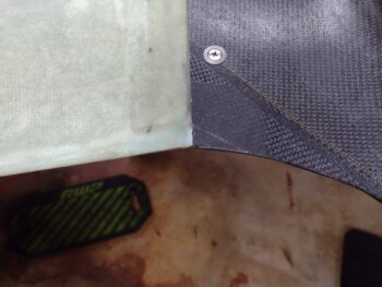
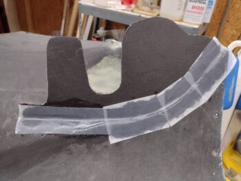
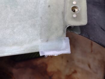
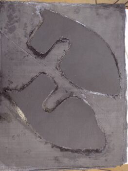
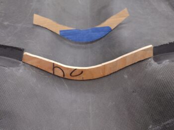
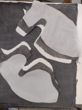
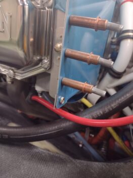
I started off today by pulling the peel ply and cleaning up the glassed foam #6 platenut tabs for the GIB headrest gap cover.  I then drilled out the glass to expose the embedded platenuts.

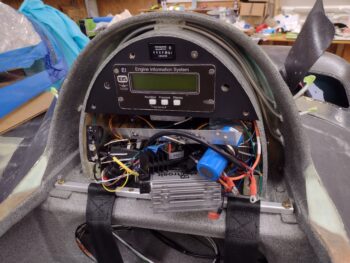
I spent well over the next hour aligning the screw holes drilled into the GIB headrest gap cover pieces with the platenut tabs and getting those positioned correctly in the gap between the GIB headrest and the interior D-Deck surface.

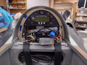
Once aligned and the interfacing surfaces sanded and prepped, I then micro’d the foam platenut tabs in place.  After about 30 minutes as the fast hardener micro started setting up, I then set the cover in place and finalized the alignment of the tabs by mounting #6 screws through the cover screw holes.  I then left the micro’d-in tabs to cure overnight.

As I mentioned before, I plan on making up another 3 tabs in the next few days for the next round of securing this cover into place.  I’ll assess after that to see if I’ll stick with 6 screws total or go with 8 to mount the cover in place.  After all the screws are in place, I’ll then apply a final ply of CF on the face of the cover to make it look spiffy and add a little strength to it (it’s fairly flimsy currently).

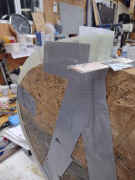
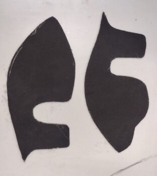
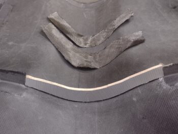
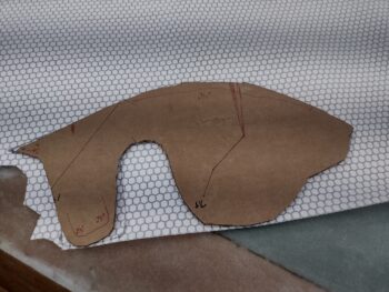
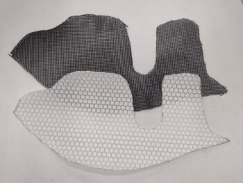
I then spent about 30 minutes prepping, sanding, trimming and finalizing the position of the left armpit air intake front ramp.  I tried to install it by using a bead of thick micro on the aft edge each side and laying up all the plies on each side thinking they would have enough grip to hold such a light piece in place.

My haste was not rewarded and it kept wanting to slide out of position a bit… the one thing I did right on this front ramp install was use fast hardener, because as I started trimming and positioning the AFT ramp, I simply kept ensuring the front ramp was still in good position.  After about 20-25 minutes of doing this, the epoxy got tacky enough that it held its position without my coaxing it.  I’ll have to be more patient during the install of the other ramps and use a bit of hot or 5-min glue to tack one side in place while I glass the other side . . .

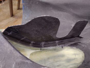
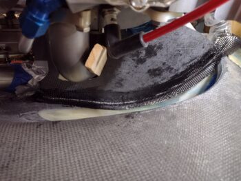
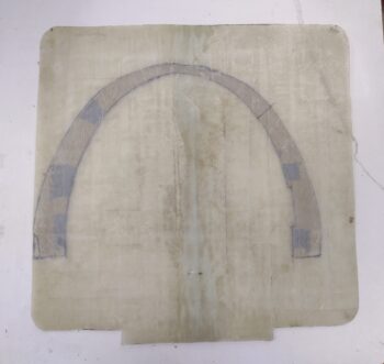
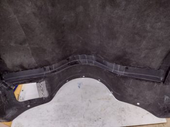
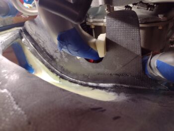
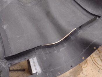
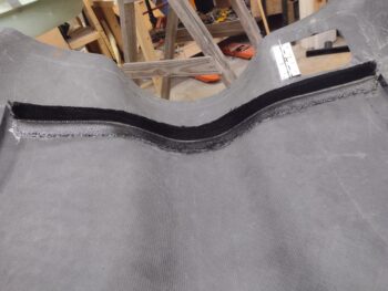
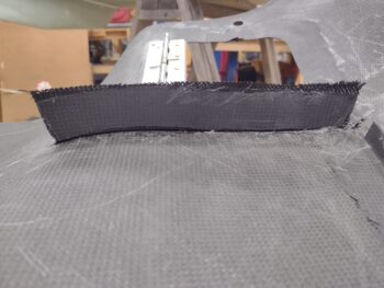
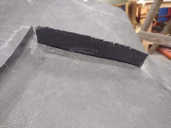
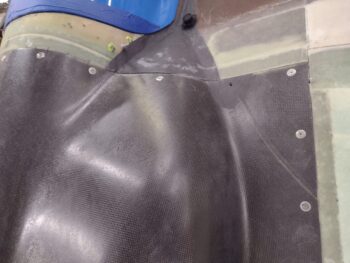
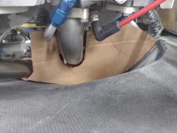
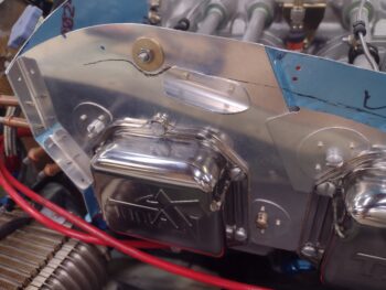
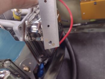
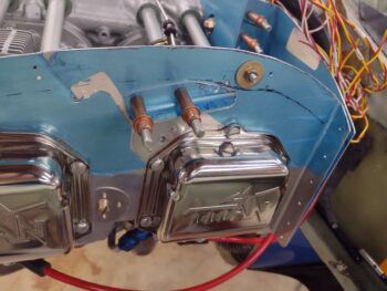
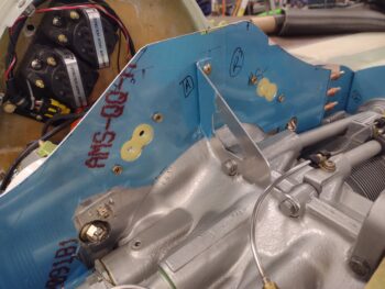
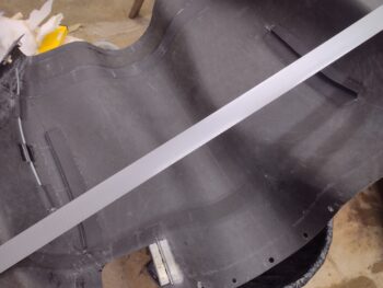
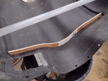
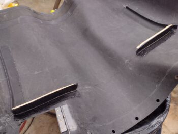
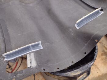
Here’s a shot of the left intake front ramp glassed in place from the front side.

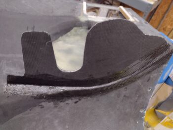
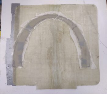
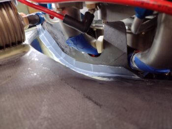
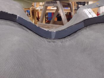
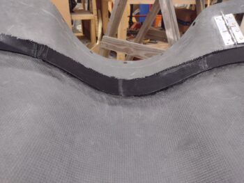
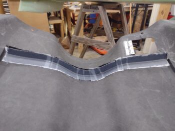
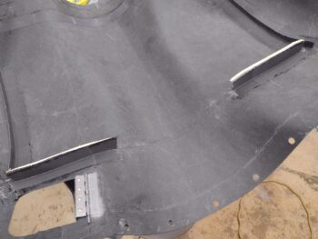
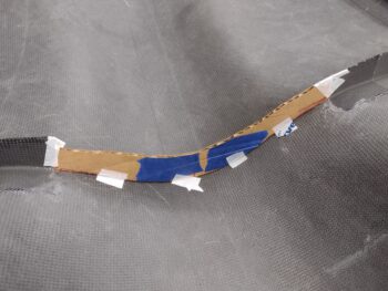
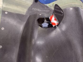
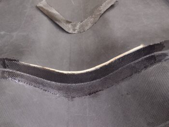
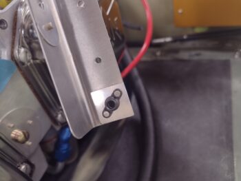
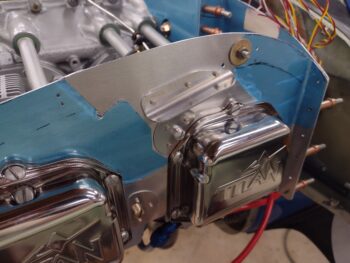
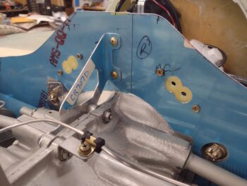
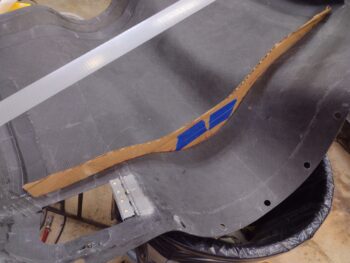
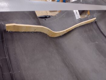
And the same from the aft side.  You can clearly see how much tweaking the aft ramp will need to get fitted into position.

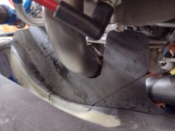
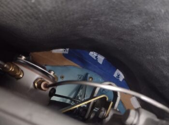
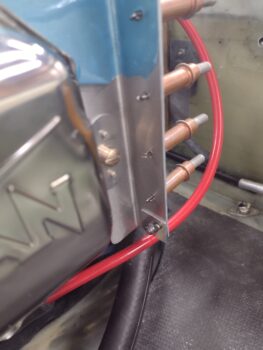
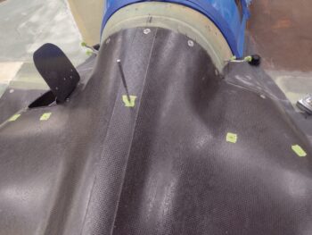
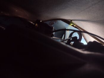
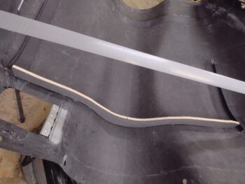
And here’s one more shot of the left intake front ramp in place with the bottom cowling mounted back on the bird.  That slight slant with the front ramp’s inboard side down is intentional in “steering” the air around the forward cold air induction tube and directing it towards the cylinder fins.

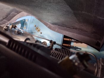
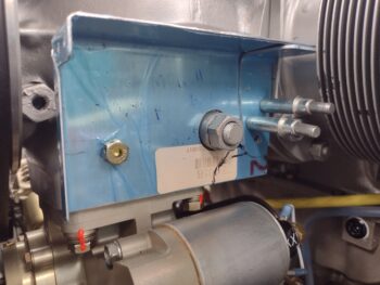
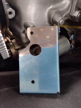
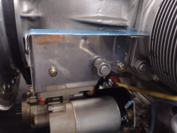
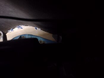
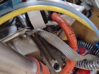
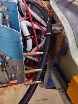
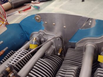
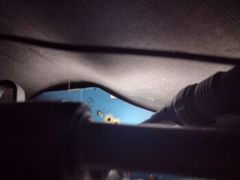
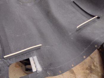
Before I mounted the bottom cowling back in place on the plane, I re-installed the left front exhaust pipe (cylinder #3) to check any interference.  Good thing too because with the exhaust pipe in place there is virtually no clearance between it and the aft air inlet ramp.

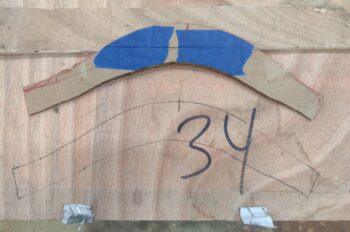
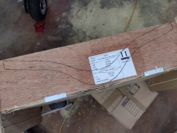
Remember, the CF piece is just the base part of the ramp and then an angled aluminum tab, or vane, gets attached to the top aft edge of the ramp.  With the ramp in the Melvill template position, I have virtually no room for a good half of my aluminum vane when mounted to the ramp.  Due to this clearance issue with the exhaust pipe, I will be moving the ramp slightly forward and angling it just a hair down to give the future attached aluminum vane some clearance.

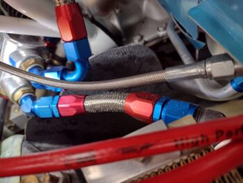
Thankfully, with the configuration on the right side of the engine, there is not as much congestion in regards to installing these inlet ramps as there is over on this left side.  Ducking, diving and snaking the air through this virtual obstacle course of air intake and exhaust pipes is quite the challenge and is beginning to be a bit of a PITA!  Now we know why so many homebuilders build tractor airplanes… much easier! (wimps! haha).

Chapter 23/24 – Inlet ramp install prep

I started out today still trying to knock out a few low-hanging-fruit items before pressing on to more serious stuff.

I started out by pulling the peel ply and razor trimming the 4-ply CF edge layup to add more depth to the screw hole on the left front edge of the bottom cowling.  I then re-drilled the hole and countersunk it (pic 1).  And then tested out a CS screw with Tinnerman style washer (pic 2).  All looking good here!

To better assess and determine mounting of the armpit air inlet cooling ramps, I mounted the bottom cowling back onto the bird.  I grabbed these shots of the CS screws and washers “in action.”  Besides a minor bit of sanding on the front edge of the added CF to better transition from strake to cowl, this task of adding CF to finalize the cowl CS screw installs is complete (and thanks again to Dave B. for the motivational push!).

Before I dove into the puzzle that is the air inlet ramps, I wanted to knock out another not-huge task: the creation of screw hardpoints between the GIB headrest and inside D-Deck surface to mount the cover around the GIB headrest.  One reason I wanted to work on this now is that to work on it I obviously have to climb in the back seat and face aft… well, squatting there for decent amounts of time causes my legs to go numb, so I want to break up the tasks in as small of time periods as I can.

I first made up the PVC foam hardpoints inside the gap between GIB headrest and inside D-Deck surface.  I then made #6 platenut assemblies using 1/32″ G10.

I then micro’d the platenuts into the foam before glassing them over with 1 ply of BID. I then peel plied the layups.  Here is a fast forward many hours later where I’ve done a rough razor trim, with peel ply still on, of the tabs.  I know they won’t win any beauty contests (neither will the fuel vent lines that are also being hidden!) as they look now, but I’ll clean them up before I install them.

I’ll also note that these are simply the first batch.  I plan on doing a batch of these every day or two to get them in place to secure the GIB headrest surrounding gap cover.

While the above tabs cured, I then did a deep dive on assessing how and where my armpit internal ramps needed installed.  I looked at a bunch of pics of Mike Melvill’s configuration, then accounted for my cold air induction pipes that Melvill did not have. It was getting later in the evening and I wanted to wait until tomorrow before I started glassing these things in… to do a final once over of my notes (I’m certain I’ll need to mod them later on, but looking for best optimization from the start).

Here we have the right side inlet inboard wall. I was pleased that the inboard walls didn’t hinder or hamper my installing the bottom cowl.  Also, note the ramp position markings on the wall side… one forward and one immediately aft of the cold air induction pipe.

After spending well over an hour looking at Melvill references and my own notes, and then doing a bit of research, I closed up shop and headed into the house.  I texted the one other person I know using Melvill CF cowlings with air cooling: Dave Anderson.  I was curious if he used Melvill’s templates as a guide or if he improvised, since clearly after a few years now he must have worked the kinks out.  Not surprisingly he did use Melvill’s templates but had a half-dozen round of tweaks to dial in his cooling (as did Dick Rutan using the same cowling).

With a page of notes in hand I called it a night.  Tomorrow morning I’ll be heading to a local EAA chapter meeting (a first for me in NC) and then I plan to get back onto the inlet ramp installs.

Chapter 23/24 – Clearing the queue!

I have a list of about 20 layup tasks (each task could be multiple layups) that need to be done on this bird to finish up the composite portion of the build.  Currently 20 seems to be the magic number since even when I knock out a few I always seem to find a few more layups that need to be done.

Well, today I decided to knock that list down just a bit more.

I started by re-drilling the 3/16″ hole in the bottom cowling front lip 3-ply CF layup I made to increase the depth of the cowling at this hole to add some meat to hold a CS screw… which is what I also drilled out.

I then test fitted the CS screw and its Tinnerman-style washer, and Voila!  Screw position #3 of 4 total on the cowlings thickened for a CS screw. . .

With the #3 screw position completed, I wanted to get #4 knocked out as well.  Interestingly, the thickness of the cowl in this position was even less than the other 3 spots, so I added 4 plies of CF vs just 3.   After laying up the 4 stepped plies of CF, I then peel plied the layup.

With a layup under my belt, I then spent a good half hour pulling the peel ply off the right intake inboard wall CF tape layup.  I then checked all the layups on these inboard walls and sanded down any rough spots or sharp edges that were lying in wait for unsuspecting fingers to draw blood… not on this bird!

I took a short break from the shop to call Sam at Saber Manufacturing to order a 3/8″ crush plate for my “new” white backup Hertzler Silver Bullet prop, since that is the last piece I need to allow me to mount that prop as well (I’ll note that I’ll need to make up a complete new spinner since the white SB prop would be offset —due to the prop extension bolt holes being offset— from my primary silver SB prop).

Back in the shop I took the 2 OSB forms that I used to originally create the GIB headrest arch structure and screwed those to the upright/vertical tab on one of my glassing boards. I then taped the GIB headrest & D-deck gap cover onto the forms to provide a working shelf, if you will, to glass on a small tab on the left side of the cover that will essentially create a “dogleg” in the cover to go around the engine electronics cooling fan.

After cutting the tab out of the same scrap glass that I used for the cover, I then sanded both the tab and the cover edge and cleaned them with Acetone in prep for a layup.

Here is the GIB headrest surround cover plate taped to the form and the small tab glassed in place with 2 plies of BID.

And a shot from the other side of the small tab glassed in place with 2 plies of BID to the GIB cover plate. I used a thick micro fillet in the corner to help secure the tab to the cover plate.  I then of course peel plied the layup.

I had just a small amount of epoxy left over in the cup from the above layup, so I took a good half hour to fill some indentions I had on the aft top cowl lower interface surface, primarily where the intermediate sections tied into each other.  After laying up a narrow filler ply of CF, each strip around 3/8″ wide on average, I peel plied these mini layups.

I then called it a night and went out to dinner with Jess.  Tomorrow I plan on focusing on the bottom cowling armpit inlet ramps to get those positioned and glassed into place.  I suspect I’ll spend a day or two on those, then once those are in place I’ll start working on the exhaust pipe configurations.

Chapter 23/24 – Inlet walls installed

You can probably tell that I’ve had some house and personal stuff to take care of over the last few days, thus I haven’t had full build days.  Although I have still been getting at least a few hours in the shop each day.

I started off today by razor trimming and cleaning up the outside layup securing the right inlet inboard wall in place.  Remember I didn’t use peel ply, so none of that to pull.

I then cleaned up the inside edge, sanded, Acetoned and overall prepped it for its layup.  I then laid up a 1-ply CF tape to secure the inside of the right inlet wall to the bottom cowling.  I then peel plied the layup.

As I was prepping the inboard side of the right inlet wall above for its layup, I also flipped the bottom cowling over and sanded off the old paint and micro to expose a small triangular area of CF cowl surface.

I then laid up 3 plies of CF on the bare CF over the screw hole (pic 1) just as I did on the top side to thicken the immediate area to allow countersinking the hole to install a nice flush CS screw at that point.  I then peel plied the layup (pic 2).

After my layups, I then cut out and cleaned up the GIB headrest/D-deck gap cover.

Here’s a shot of the initial fitting from both sides to get a better view of each side.  Notice on the left side (right in pic) that I cut the lower side of the cover to create a dogleg that will eliminate any obstructions for the engine electronics cooling intake fan.

It took nearly 45 minutes of minute sanding and trimming to get the cover set in place without any major gaps and so that it fit as well.  Remember, once I get it dialed in and very close, then the securing hardware (most likely 4x #6 screws) I will then do a final layer of CF on top.

Here we have a straight on shot.

And with that, I called it a night.  Tomorrow I plan on working the armpit intake ramp placement and installs, in addition to some aluminum vane cutouts.  Also, I plan to start working the exhaust pipe runs in the next day or two as well.

Chapter 23 – Right inlet wall install

I started off today by trimming the glass and shaping the flox on the small gap fill I did on the left wing inboard trailing edge, where it interfaces with the aft left TE of the top cowling.  Once I shaped the wing side, I then mounted the top cowling to check the gap… which obviously looks way better now that it’s filled.

I then removed the bottom cowling, pulled the peel ply off the 1 ply CF tape layup that I did to secure the outboard side of the left armpit intake inboard wall.  I then razor trimmed and cleaned up the cured layup.

After some more trimming of the left side intake inboard wall to allow better clearances with the cold air induction tubes, I then laid up a 1-ply CF tape on the inside of the left side air intake wall.

I then peel plied the layup.

I had to run out to do some errands for a good part of the day, and upon returning early evening I mounted the bottom cowling back onto the plane and got to work on the right armpit air intake inboard wall.  I spent a good 45 minutes trimming the inboard wall and finally got to a point where it was ready to install.

With the cylinders on the right side of the engine offset forward as compared to those on the left, it made the initial layup of the single ply CF tape significantly more challenging than the left side.  Another minor issue I had was actually securing the inboard wall in place while I glassed it.  For this reason I actually did NOT peel ply this layup as I wanted to minimize any added disturbance of the inboard wall… since I really had to do some contortions to get my hands in there to get this layup completed.

With this challenging layup under my belt, I called it a night.  Tomorrow I plan on laying up the CF tape on the other side of the right side inboard wall to finish securing it.  I also want to start work on getting the air inlet ramps installed as well.

Chapter 23/24 – Left inlet wall install

I started off today doing a few sideline tasks as I waited for the top cowl cross rib baffle to cure with the top cowl mounted in place for at least 24 hours, since I used Pro-Set epoxy for the final cross rib baffle layup.

I grabbed the Aft nose/avionics cover and pulled all the surrounding overspray paper off before taking the cover outside and first lightly sanding it with 220 grit before then wet sanding it with 350 grit.  This knocked off quite a few nibs but also exposed some underlying colors in the process, such as white dots now appearing in the black squares, which I’ll simply touch up.  However, it made a huge difference in smoothness that I could tell just by running my hand across the painted surfaces.

I’ll carve an hour or two here and there out over the next month to attack each color at a time with touchups and let those cure at least 48 hours before going onto the next color. When all 3 colors have been touched up and cured, I’ll then clear coat the panel.

Although I could clearly fly without either the above or this next task being completed, personally I don’t want have a dozen nice-to-do projects staring me in the face after I get this thing flying.  Especially since I’m sure I’ll have more important mods to tend to such as ramp vane/engine cooling adjustments, avionics configuration tweaks, etc.

Since I decided to copy Chris Randall’s method of running my fuel vents out the sides of the Turtledeck, it’s clearly made the area surrounding the GIB headrest/engine electronics compartment pretty gnarly and industrial looking.

I took about 45 minutes to create a cardboard template that surrounds the GIB headrest and fills the gap between it and the outer Turtledeck shell to hide those unsightly fuel vent lines.  However, I will have to do a few rounds of extra layups on this cover mod to allow for the electronics cooling intake and exhaust fans that are at roughly the 4 and 10 o’clock positions when looking at the front face of the engine electronics bay.

I have a cut OSB (“plywood”) mold that I used for the shape of the GIB headrest that I’ve kept since I made the headrest/electronics bay wall.

Ironically, as I was looking for it out under the carport that hangs off my shop, I ran across the very dirty extracted 2-ply UNI piece of exterior fuselage skin that I cut away to expose the area that I would create the depression for the landing brake on the bottom of the bird.  Unlike the plans process, here I taped up the area of the landing brake before glassing the outside of the fuselage… thus was able to simply cut and pull this piece of fiberglass off the bird without all the foam and gunk attached to it.

As I was pondering how to glass this GIB headrest surround cover, I was thinking it would be nice to have a starting substrate, preferably one that was all in one piece… clearly I had an Aha! moment and went and retrieved this very flimsy panel of fiberglass I’ve kept around for over 10 years now.  I cleaned it up with Simple Green and the hose before sanding it down on the exterior (non-tape facing) side and pressed it into service.

Since this panel is only 2 plies of UNI thick, I wanted to make it just a bit stronger as I add a kink to the lower left side (right facing camera) for the air intake fan.  Moreover, my plan is to get the final shape and kinks dialed in and then do one final layup on it with CF as the outboard facing surface… yep, fancy!

I taped my cardboard mockup template to the back side of the UNI panel and then outlined it with a thick black Sharpie.  Since I could see right through it that allowed me to do my initial added ply of BID layup on the front without worrying about messing up my marked line, which just isn’t my layup perimeter, but also my cut line.  I then peel plied the 1-ply BID layup (I used West epoxy here with fast 205 hardener).

By this point I was past my 24-hour cure time on the top cowl cross rib baffle, so I removed the cowling, marked my trim line on the peel ply and trimmed the layup with my Fein saw.  I then removed the peel ply and cleaned up the layup.

Of course I then quickly remounted the top cowling to check the fit and clearances of the top cowl cross rib baffle.  It’s a bit close to the actual front baffle wall, so at some point in the future I may trim the cross rib baffle down a bit more… especially if it interferes at all with the rivets that secure the baffle seam.

With the top cowling off I then had access to the armpit inlets.  I sanded the rough edges of the intake inboard walls, and then spent about 20 minutes dialing in the shape of the left side inboard wall.

After another half hour of fine-tuning the shape, clearance and positioning of the left intake inboard wall, I pulled the trigger and secured it in place with a 1-ply CF tape in the intersecting corner on the outboard side.

I then spent another good little bit reaching in there to peel ply the layup.

Tomorrow I’ll pull the bottom cowling off and layup the inside corner to finish securing the left intake inboard wall.  I already know that I need to do a bit more trimming on the aft side as well.

I had just a bit of epoxy left in the cup (par usual!) so I decided that my last task of the evening would be to layup a ply of UNI and a ply of BID overhanging the left wing inboard TE by about 1/4″.  I then added a blob of flox on the aft TE corner pressed into the now overhanging glass above it.  I then peel plied the layup.

This layup with flox is to remedy the noticeable gap that I have —obviously on the wing side— between the left wing TE and the top cowling left TE.

Tomorrow my main goal is to get the right inlet inboard wall shaped, positioned and “glassed” (CF) in place.  From there I’ll start working the inlet ramp installs.

Pressing forward.

Chapter 23 – Cross rib baffle glassed

I started out today by taking the armpit inlet inboard wall layups outside and cutting the walls out.  They’re still in the rough just-cut state and I’ll sand down the edges tomorrow.

I then got to work on the top cowl cross rib baffle front side 2-ply CF layup by first pulling the peel ply (after taking the top cowling off the bird) and then cleaning that up.

I then pulled the wood form and cleaned all the hot glue off.  Remaining was the initial peel ply that I put on before laying up the center front 2-ply CF (pic 1).  I then pulled the peel ply off and cleaned that up as well (pic 2).   I then prepped the entire aft side of the top cowl cross rib baffle and —don’t forget!— stiffener for the aft side layup.

I had some single strands of CF UNI left over from a long time ago, and decided to use those as filler at the base of the front layup to fill the resulting bottom gap (corner radius) and create a bit of a fillet as well.  I have to say, it worked pretty darn well.

I then added in 2 plies of 1″ wide UNI to help strengthen this cross rib baffle and stiffener, in addition I added an extra ply of CF to make it 3 total on this layup, 5 total for the cross rib baffle/stiffener.  Here’s all the CF and UNI laid up.

I then peel plied the layup.  All in all it took well over 3 hours just to prep and do this layup, but I think it turned out PDG.

I then left the layup to cure… and just like last night I’ll let it cure for a good 4-6 hours to set up and then mount the top cowling back onto the bird to have the final cure happen “in situ.”  Tomorrow I plan to start working the armpit inlet walls and ramps full bore.

Chapter 23 – Cowl cross rib, part 2

Today was a much warmer day than it has been in the last few weeks, and I had promised Jess if we had another nice warm day we’d either take the boat or the bike out.  I didn’t want to mess with prepping the boat or making an entire day of going out, so we just hopped on the ‘ol Harley and cruised out for a few hours.

Before Jess came over for our scoot, I wanted to get something knocked out on the plane build.  I decided to add the first of two reinforcement plates for the aft right baffle Melvill-style bracket.  I of course had some VAN’s baffle kit right angled brackets on hand so I repurposed one of those and pressed it into service as a reinforcement plate.

After lining up the new bracket plate on the front edge of the “Melvill” bracket I drilled a hole and then installed a Cleco to secure it.  Then another hole and another Cleco.  All told I drilled 4 rivet holes.  In addition, if you look at the bottom front corner you can see where I marked the Melvill bracket for trimming since there is no engine surface behind the bracket in that area.

I then trimmed the Melvill bracket, the reinforcement bracket, countersunk the rivet holes and riveted the repurposed bracket (I guess these are both repurposed eh?) into place.

Here’s the final product for this first reinforcement plate on the Melvill bracket.  The aft reinforcement will also go upwards but also aft and will look a bit like a reverse ‘L’ or ⌋ shape.

Although I plan on letting them cure fully until tomorrow before cutting out the armpit inlet inboard walls, I also went ahead and pulled the peel ply off of those layups.

After getting back from our ride where we hit a little coffee joint out on the beach, I then got back into the shop to work the top cowl cross rib baffle.

Here we have the outboard segments of the top cowl cross rib baffle with the peel ply pulled.

I then removed the wood forms, pulled the aft side peel ply and cleaned everything up for the left outboard side (pic 1) and right outboard side (pic 2) segments of the top cowl cross rib baffle.

I then spent about half an hour dialing in my initial cardboard template to the shape of the center area of the upper top cowl… after remeasuring the width of the cowl as it was installed in place on the plane.

Apparently my installed cowl-width measurement was much better this time around (And I was a bit over 1/2″ off the last time from this measurement) as when I test fitted the cowl with the top cowl cross rib baffle cardboard template in place, the fit was spot on.

I then outlined the cardboard template onto the plywood top lid for the metal brake crate.

I then cut a new wood form for the top cowl cross rib baffle center section, and after a couple minor tweaks it fit right into place between the 2 outboard segments.

I then double checked my wood form fit by taping it into place and remounting the cowl…

And installing nearly all the CAMLOCs around the perimeter.  All looked good this time around!

I then cut 2 plies of CF and the initial peel ply that matched the shape of the wood form.  I then added duct tape as a mold release to the front of the wood form and hot glued it into place, again between the existing outboard segments of the top cowl cross rib baffle.

I then laid up the first ply of CF, after I wet out the peel ply that covered just the taped portion of the wood form (not any on the cowling).  Not wanting to add any more forward surface depth of the top cowl cross rib baffle, I only overlapped this first ply onto the existing outboard segments by about an inch each side.

The second CF ply was shorter in width and did not overlap onto the existing segments as the first ply did, but was just pretty much the shape of the wood form on the vertical side.

I then peel plied the 2-ply CF layup.

I used Pro-Set epoxy to give me a fairly long cure time, so first thing in the morning I’ll mount the top cowling into place so that the final cure of this center top cowl cross rib baffle section will set with the top cowling secured into place with all the CAMLOCs installed.


Chapter 22/23 – Air intake inner walls

I started off today by pulling the peel ply and trimming the sides of both outboard 2-ply CF layups for the top cowl cross rib baffle/stiffener.  I then mounted the top cowling back on the bird to check for any possible clearance or obstruction issues, but all was good (no pics).  I of course meant to do the next round of layups on the cross rib baffle later in the evening to let it cure overnight… but ran out of time.

Before I mounted the bottom cowling to work on the armpit inlet inboard walls, I wanted to get another smallish task knocked out: the engine ground strap attachment.  I discussed different engine ground strap attach points with B&C Electronics and was “cleared hot” by them to mount it to the front right corner edge of the oil sump.  The only issue is that when I ordered this ground strap from them years ago, each end was meant to attach to a 5/16″ bolt.  Now this end is attaching to a 1/4″ bolt.

In the recent past I had looked around for a small insert to use but didn’t have any, and honestly couldn’t find any anywhere online.  I ended up ordering some raw stock from McMaster-Carr and since I don’t have my Lathe CNC finalized yet, decided to simply trim a width off of it that is as thick as the ring terminal: ~1/16″.  I then spent less than 10 minutes filing the insert to final thickness and to remove the Dremel cut marks.

I then removed the front right bolt from the oil sump lip.  Now, I had originally planned to mount the grounding strap on the top of the oil sump lip, but it was too close to the engine mount ring when pointed in the direction it needed to be to reach the firewall post, and stretched too tight if I kicked it out in different position… so I mounted it on the bottom of the oil sump lip.  I then added some blue Loctite to the bolt threads, applied some Dielectric grease to the ring terminal, replaced the star washer and then torqued the nut back to 96 in-lbs.  I then did a continuity check from the far unattached end of the ground strap to the bolt stud on the starter and it rang out nice and loud.

Voila! Engine ground strap installed on the engine side.

I then mounted the bottom cowling and spent a good half hour finalizing the shape of the left side armpit inlet inboard wall.  I then used the cardboard template to cut out a ply of Lantor Soric filler material, with some minor mods (I didn’t want to have to remake a whole new template).

I then used the Lantor Soric to cut out a ply of CF for the left side (I explain below how these are used).

I then spent nearly 45 minutes working the right side template for the armpit intake inboard wall.  I don’t show Mike Melvill’s original template here, but just like the left side template mine is significantly different than his.

I then did the same thing with the right template by using it to cut a ply of Lantor Soric, and then using the Lantor Soric to cut a ply of CF.  I then cut peel ply for both side layups (pic 1).

Now, included with the Mike Melvill cowlings from Feather Light was a large flat piece of 3-ply (I’m assuming?) CF.  It’s a bit too thin and flexible (emphasis on thin) for how I want to employ it, which is a bit more outboard than Mike had his (it appears my ramps are a tad narrower than how Mike Melvill’s ended up… which is fine).  I kept going back and forth but eventually decided I wanted these inboard walls just a bit thicker, thus the Lantor Soric getting added to the 3-ply CF sheet with another ply of CF over the Lantor Soric… as you can see that’s exactly how I laid it up (pic 2).

I then of course peel plied both layups and since I used Pro-Set epoxy I set them aside to cure overnight.

I was heading out for a later dinner with Jess so I decided to simply knock out a couple more baffle tasks since I wouldn’t have enough time to make a new top cowl cross rib middle template/form and then do a layup.

Again, I have a couple rivet holes remaining on the left side front baffle that are not in an area that will simply allow me to cover them with baffle seam material.  As I did on the right I trimmed the length of the front side stiffener way down and then cleaned it up, final drilled the #30 holes and mounted the stiffener with 2 rivets.

My next baffle task entailed a bit more machinations.  First off, while the bottom cowling was off I took a good look to assess the run of the crankcase vent hose.  In the vicinity of the lower right front baffle/cylinder 4 corner is where a 5/8″ aluminum tube will get secured inside the hose to then run along the exhaust pipes so anything coming out of the hose/tube will get burned off at the exhaust exit.

You can see in the pic below that the crankcase vent hose is secured upstream to the engine mount frame with an Adel clamp, and I need another one at the bottom front corner of the baffling to again secure the hose.

Whether the Adel clamp gets secured directly to the bottom corner or maybe with an intermediate angled tab, I need to be able to bolt either to the bottom corner of the baffle.  I drilled out the bottom rivet hole to 3/16″ and then grabbed a scrap square of 0.040″ thick 2024 aluminum as a reinforcement doubler and cleaned it up.  I then mounted an AN3 platenute just to the side cylinder 4 baffle segment with countersunk rivets.

I then reassembled the front right corner baffle segments and threaded in an AN3 sized bolt.  Again, I may need to make up a small tab to secure and angle the Adel clamp in the correct orientation, but the hardpoint for attaching all that is now in place.

I was expecting to receive the cylinder baffle forms by today, but I haven’t gotten them yet.  If I don’t receive them by Tuesday I’ll ping my contact to see what’s going on.  I plan on finishing up the top cowl cross rib baffle over the next couple of days and add some reinforcement brackets to the “Melvill” baffle bracket on the aft right side.  After that, I may add some baffle seal material around the front and side baffles a bit, but I can’t really do any more on the baffles and will roll into working the exhaust pipes and prepping for micro finishing the remaining parts of the bird.


Chapter 23 – Top cowl cross rib

I started off today with the goal of getting both the top cowl cross rib baffle front half glassed as well as the bottom cowl inlet inboard wall shapes finalized and glassed.  They say if you’re reaching all your goals then you’re not setting them high enough… I’d say I’m ok in that department! ha

I did have one planned baffle task to do in support of prepping for the top cowl cross rib baffle, and that was to mount the front baffle wall center support bracket that attaches to the center engine crankcase bolts (see below).  The unplanned baffle task I got caught up in is that as I was doing some mental inventory on what is left to be done on the front/left/right baffle sides, I noted the pre-drilled holes in the front side baffles for the included stiffeners in the VAN’s baffle kit.

As I was pondering how to fill those holes, I figured I would just throw a rivet in each hole and call them sealed.  Then I thought, well, why not make them useful?  I set the right side stiffener in place and realized I could simply use it in its shortened state… who knows, it might prove useful in providing an Adel clamp mounting tab in the future?

I shortened the stiffener using my Dremel tool then riveted it into place.  Clearly I wanted to ensure it wouldn’t interfere with the baffle seal material mounting.

I did add one more rivet towards the front side, and here you can see that more clearly from the inside of the baffles (note: I’ll assess and most likely install the left side stiffener within the next few days).

I then mounted the center bracket to secure the front baffle wall.  I have to say overall I’m quite impressed with the VAN’s baffle kit since they even include new star lock washers to replace the ones I removed when I temporarily removed the crankcase bolts to mount the bracket.  I then retorqued the crankcase bolts to 96 in-lbs.

There were pre-drilled bolt holes in the vertical tabs of the bracket but not surprisingly no holes in the front baffle panels, so I drilled those out for an AN3-sized screw.  Note since these baffles are for RV tractor aircraft that they are a tad too short in the middle to reach to within a half inch of the inside top cowling…. clearly at the flat part.

I had been thinking about making a forward stiffener in the top cowl after a discussion with Marco months ago how he noted in some videos he took while flying that his Long-EZ’s top cowling was distorting a decent bit while in flight.  My thought on combining the top cowl forward stiffener with a forward cross rib baffle (like the side rib baffles, only 90° to those) was re-confirmed in a response to my COBA baffle question from Klaus Savier who said his cowling rib baffles also serve a dual purpose as cowl stiffeners.

Thus, in lieu of messing around with heightening the front baffle wall in the center to get it close enough to the top cowling, I would simply make a combo cross rib baffle/cowl stiffener and call it good.  Plus, the slightly lower profile center front baffle wall will give me a slightly better visual when swapping out the oil filter.

I took measurements of the front baffle wall to different spots along the front edge line of the top cowling, and then put the top cowling back in place.  I then drilled very small diameter holes at those measurements.  I then inserted a straight dental pick into the drilled holes to determine my distance from the front baffle wall and annotated any corrections onto tape at each hole.

I made my fore/aft assessment of the distance from drilled hole to front baffle by either looking into the oil check door or from the aft end of the cowling with a light (pic 1).  Also, I verified the gap from the center of the front baffle wall to inside top cowling as just over 1″.  To be clear, if I wasn’t looking to specifically install a top cowl stiffener I probably would not have proceeded with installing a top cowl cross rib baffle.

I taped the top cowling on the outside with the duct tape taut and did an eyeball top cowl width measurement with my tape measure.  I then removed the top cowl and flipped it over and taped across the bottom to bring the outboard tape taut and at the distance of my eyeball measurement.  I also made my corrected cross rib baffle line across the cowl using the drilled holes as references (pic 1).

I then made up a cardboard template for the cross rib baffle (pic 2).  Now, I should have taped the template in place and put the cowling back on to ensure my template was tracking the inside surface of the top cowl when it was mounted in place.  But I didn’t, since mentally I guess I had already captured the “mounted cowl position.”  This proved to be a significant error.

I then used the template to cut out a plywood form.  Again, it all appeared well as I test fit my form inside the top cowling.

I then taped up the front side of my form and hot glued it into place.

When I went to mount the top cowl into place I could tell I was about a good 1/2″ off my cross measurement, as the sides were in just a bit too much to mount the top cowl back in place.  After messing around with it for a while, I realized my lack of due diligence in checking the cardboard template had brought me to a point of having to call NO JOY on the plywood form… at least, a fair bit of it.

I decided to get some CF curing and simply lopped off the low “threat” flatter sides and hot glued those back into place. I then remounted the cowling to check their fit and all was good.

I then cut and laid up 2 plies of CF on each side.

And peel plied the 2-ply CF layups.

After nearly 2 hours of curing, right before I went to bed, I went back out to the shop and mounted the top cowl into place to ensure the top cowl would be in its normal mounted state as these layups went into final cure.

Thus, instead of a one-time layup for the front side, clearly this will be yet another iterative process with a few layup cycles (oh, well… pressing forward).