Chapter 23/24 – Inboard exhaust pipe

I started off quickly brushing on a couple rounds of flat clear coat to the areas I hand painted around the GIB headrest & D-deck gap cover… to get that knocked out.

Actually today was all about getting the left inboard exhaust pipe mating surface trimmed at the proper angle to seat against the 90° elbow portion of the exhaust pipe that is bolted onto the cylinder #1 exhaust port.

This is one trimming session of 3 total that I did, after a good 10+ minutes of assessing height, angle, standoff from spinner flow guide, etc. in between each round of trimming.

Here we have the final trim of the left inboard exhaust pipe.  After I dialed in the angle and position, I texted James to see if he would be available tomorrow to weld this up.  I’ll note that there are actually 2 welds that need to happen here, since under that ring of black tape is another spot where the pipe is cut in two.

BTW, James did say he was available so the plan is to get this exhaust pipe welded up tomorrow… Hoo-ah!

After another 45 minutes assessing the exhaust pipes and upcoming aft engine baffle construction, I closed up shop and headed out to dinner with Jess to relax for a bit.  Just before dinner I finally picked up some #6 SS hex button head screws for the GIB headrest & D-deck gap cover.

Upon my return home later, I mounted the GIB headrest & D-deck gap cover with the screws I had just acquisitioned a few hours earlier.  Here’s how it all looks.  Not too bad, in my opinion!

And some closer up shots each side.  Can you pick out the areas that were hand painted?  Hopefully not!  I do need to still do some minor sanding and tweaking around the edges, as well as fix the rough edge on the one side… but overall?  I’m pretty darn pleased with how it turned out.

I then spent a good half hour plus removing the tape and cleaning off the gunk, as well as cleaning up the mating edges of the different left inboard exhaust pipe pieces in prep for them getting welded up tomorrow.  I then called it a night.


Chapter 23 – Welding plan kickoff!

Today was the day I FINALLY kicked off my long-overdue exhaust pipe welding plan with James.

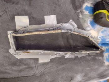
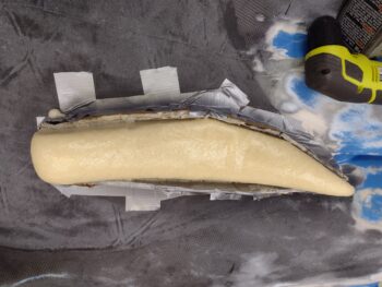
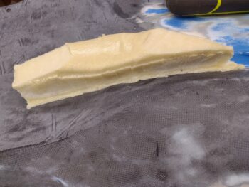
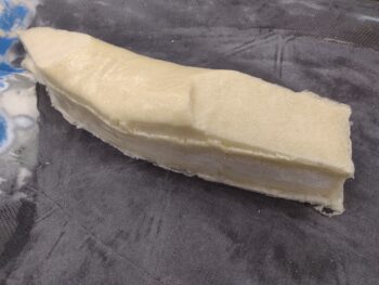
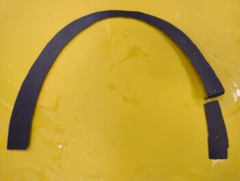
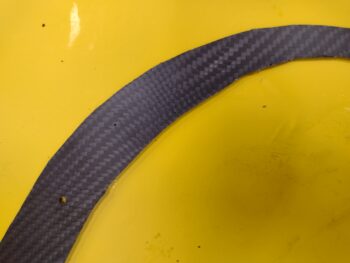
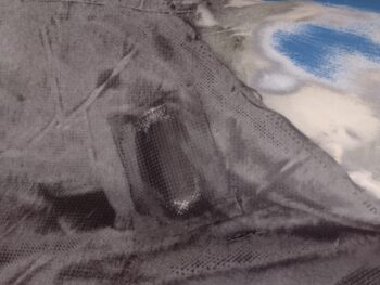
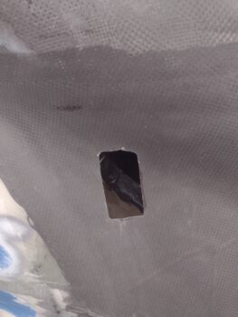
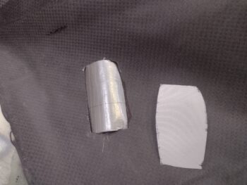
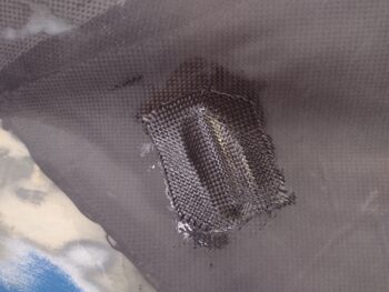
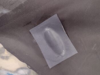
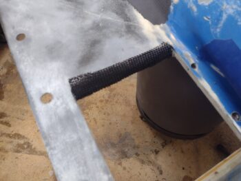
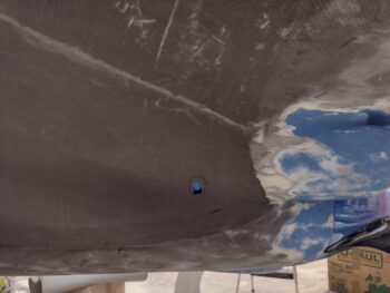
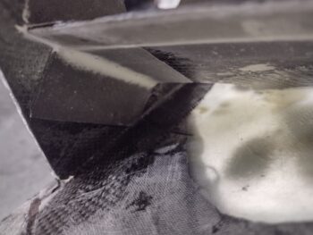
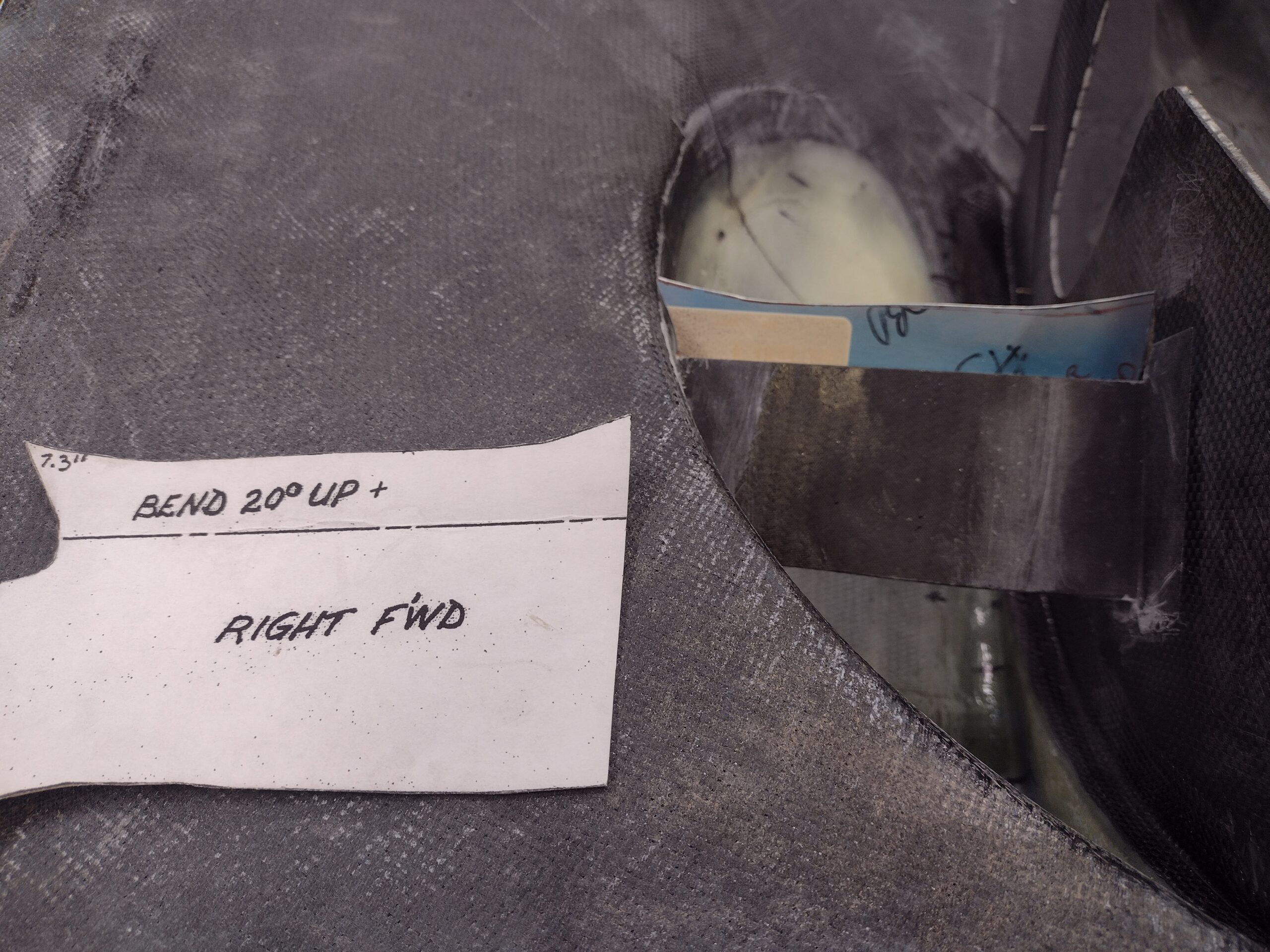
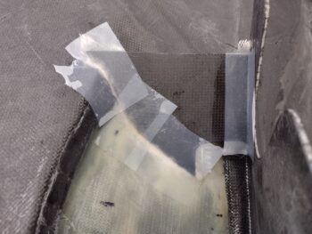
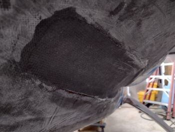
But first I pulled the heat lamp off the CF layup on the right side cold air induction pipe bump, and then pulled the peel ply.  I then cleaned up all the peel ply boogers.  As you can see, there is still a very slight bump from the original bump in my added foam fairing, but I will mitigate that with both some aggressive sanding and added micro when finishing.  Overall, not bad and definitely does the job in both adding needed clearance for the aft right cold air induction pipe, and not creating a heinous goiter on the side of the bottom cowling.

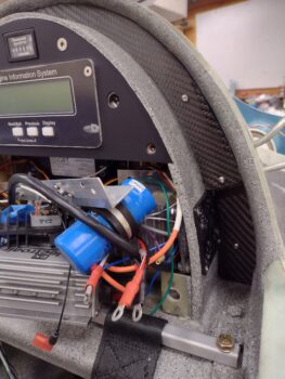
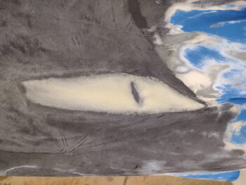
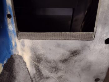
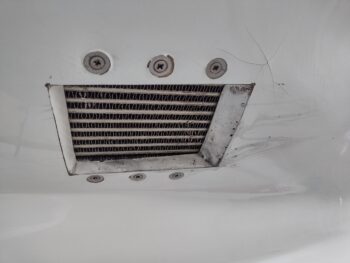
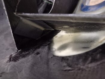
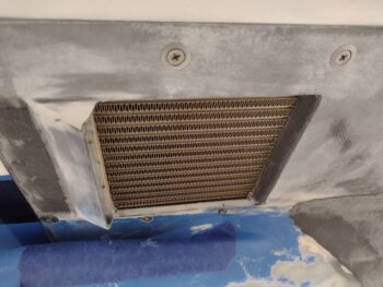
While the bottom cowling was on, I remembered to grab a shot of the newly angled aft oil cooler exit.  Not crazy distinct in nature here, but definitely a significant angle created.

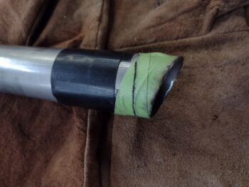
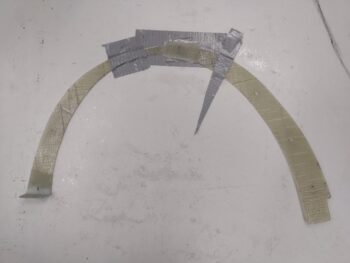
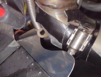
I then did a very final assessment on the left outboard (cylinder #3) exhaust pipe position before pulling a good bit of the duct tape off the pipe that was securing the cut exhaust pipe to the engine-side elbow.  I then marked the position as best possible across the hose clamp.

I then removed the bottom cowing and both left exhaust pipes from the engine.

Now, with that duct tape on there for a LOT of months, it required about 30 minutes more than I was planning on to get it off there and cleaned up.  Cleaning all the tape gunk off the exhaust pipe made me a bit later getting to James’ home shop than I had planned on, but all was good (I’ll note the drive from my place to his is right at about an hour).

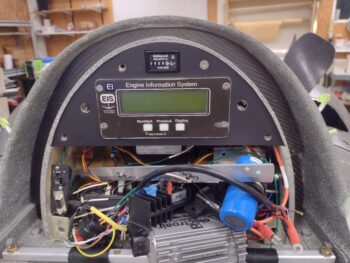
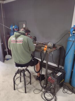
After we bantered about a bit on the exhaust pipe welding plan, airplane homebuilding and military war stories, James dove right in on welding up the first weld on the cylinder #3 exhaust pipe.  Again, this is James’ home shop and I noted right off the bat that this guy —who welds up race car exhaust headers for a living— has the exact same TIG welder in his home shop that I do!  That made me feel like I’ve made at least one right decision along the way… ha!

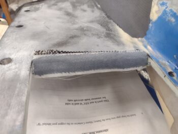
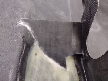
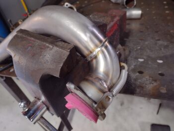
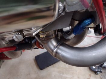
Here’s James’ beautiful TIG weld on the cylinder #3 exhaust pipe.  Note the pink cap… the other end of the pipe is capped as well and is flooded with inert gas on the inside as the pipe gets welded.  This creates a strong, clean, porous-free weld.  Again, even if I was inclined to tackle this welding, I would need a setup like this to do it (we’re talking a decent bunch of $$$ for essentially a one-time task).

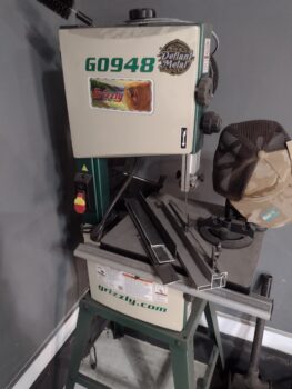
As James was welding up the pipe I of course was not directly watching what he was doing with no welding helmet on, so I wandered around his shop a bit.  James has a huge Grizzly bandsaw in a central location along the wall of his shop, but over in the corner he had this smaller Grizzly bandsaw.  Since my small Skill bandsaw has never been a top performer, I noted this G0948 model in the corner and thought that it looked like a perfect size for what I need, since I honestly don’t do a ton of bandsaw work.

As we were talking after James finished welding up the exhaust pipe, I asked him how he liked this smaller bandsaw in the corner.  He said a friend of his bought it new, never used it, gave it to him and it’s sat in the corner unused for 2 years now.  He offered it to me for a steal, practically giving it to me, and I of course couldn’t refuse (remember, I’m cheap!)… so into my vehicle it went.  Hopefully my bandsaw woes are behind me now! <grin>

From James shop I drove into town and spent some time there, grabbed a bite to eat and then finally got home later in the evening.

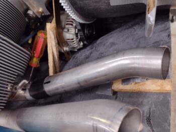
I mounted the freshly welded #3 cylinder exhaust pipe onto the engine, and it looks great.

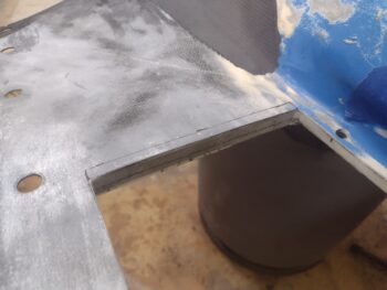
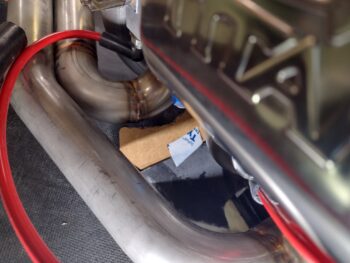
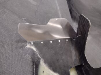
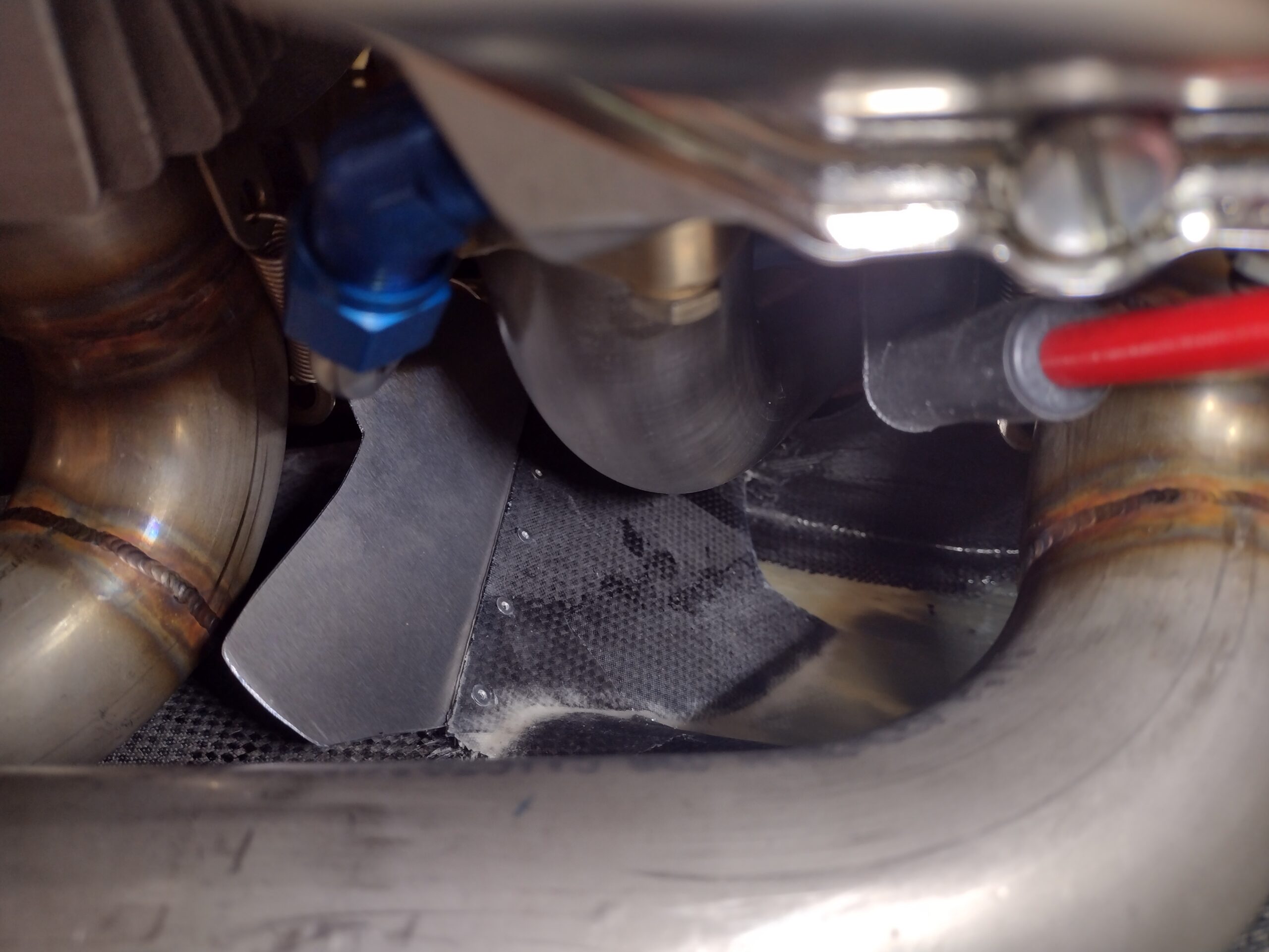
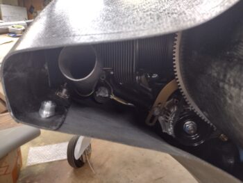
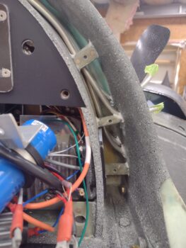
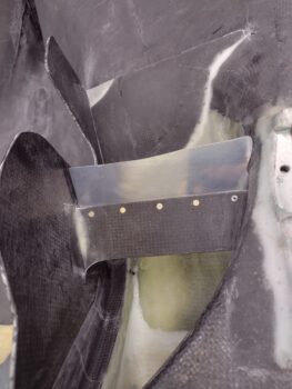
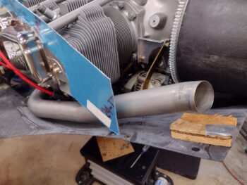
I then mounted the bottom cowling into place.  Here we have the clearance between the armpit intake aft ramp/vane with the #3 cylinder exhaust pipe without the tape and hose clamp in place.  I plan on trimming about another 1/8″ off the outboard edge of the vane, and then we’ll be good on clearance.

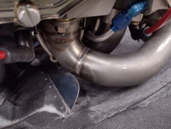
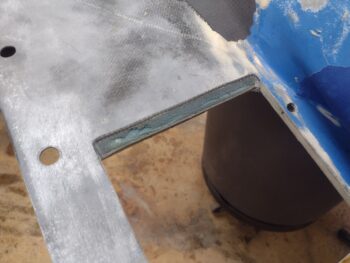
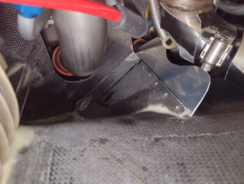
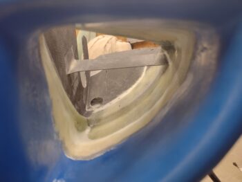
This shot here shows the area I was most concerned about on this round of welding up the #3 cylinder exhaust pipe.  I wanted to get the pipe as high off the bottom cowling in this area as possible.  My measurement on the aft side of the pipe (right side of pic) was 0.7″ from the exhaust pipe to the 3rd fin in on the aft bottom corner of the #1 cylinder.  When I measured it here that gap was 0.65″… perfect!

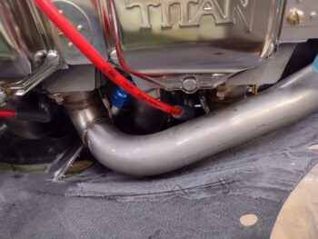
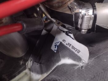
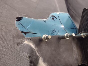
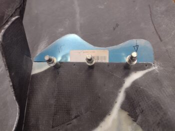
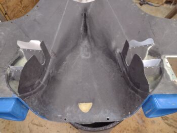
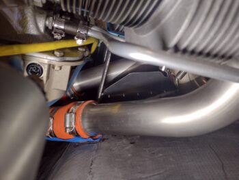
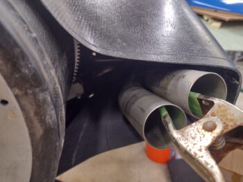
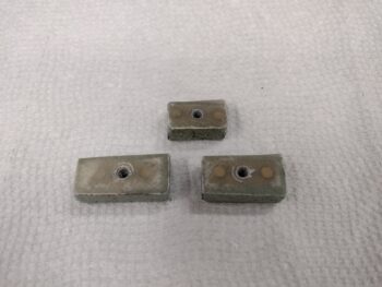
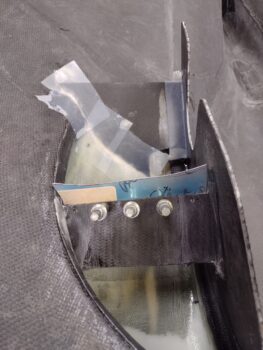
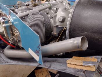
I’ll work the left inboard pipe next, and get it welded to its bare elbow sticking out of cylinder #1.  After a round or two of welding on the inboard left exhaust pipe, then I’ll come back to the outboard pipe again and get it situated.  Note the approximate distance from bottom cowl to where the bottom pipe end opening edge should be… about at the top of the wood spacers.

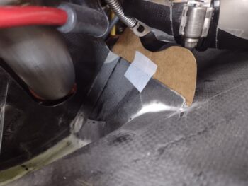
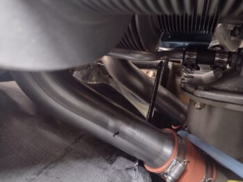
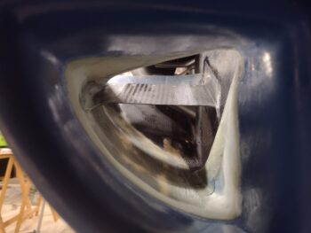
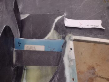
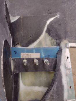
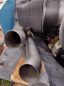
Here’s a better look (sorry for the fuzzy pic)… you can see right about where the outboard pipe meets the starting elbow of the inboard pipe is where it will need to get turned downward and slightly inward.

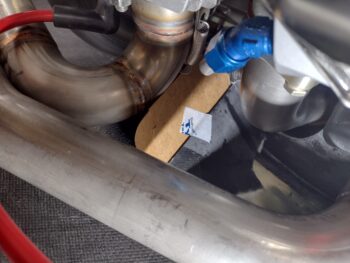
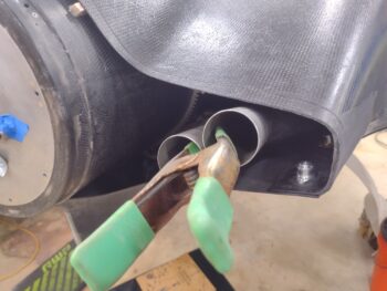
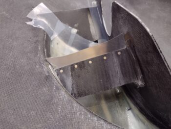
This pic shows that even a bit more… I set the inboard pipe loosely in place, close to its final exit elevation.  See how the outboard pipe will need to get angled down and inboard a bit?

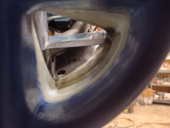
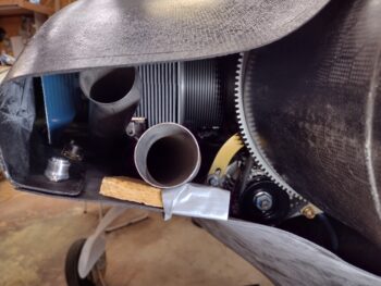
And a shot of this with the top cowl in place, which really shows you what machinations need to take place to get these left side exhaust pipes wrangled into place.

But how do we eat an elephant?  One bite at a time!  And that is exactly how these left side exhaust pipes will get configured into the final positions they need to be.

Pressing forward!

Chapter 23 – Right cowl bump, Pt. 2

I started out today by doing a final sanding in the area around the bottom cowling right side bumpout that will provide needed clearance for the aft cold air induction pipe.

I then made up a pour foam dam in preparation for the foam.

Since this part of the cowling is on a curve, and any liquid —including pour foam— seeks a level plane, I needed to use a bit more pour foam than I would have wanted to.  It’s hard to judge on this stuff sometimes, and I definitely wanted a bit too much than too little… and that’s what I got.  I didn’t want any pour foam seams here.

I don’t have any shots of it, but last night I dabbed on some coats of primer on the hard-to-reach unpainted areas around the GIB headrest and inside turtledeck.  During this half hour waiting period for the pour foam to cure, I sprayed some gray rock paint in a cup, added a little bit of micro to thicken it while also adding a little bit of Acetone to thin it (yes, these may seem like opposing actions, but it needs both to still be a pain to apply with a brush).  I then added a sloppy coat of the gray rock paint over the previously applied primer.

I also contacted my welder James and let him know that I was ready to kick off our exhaust pipe welding adventure.

I then got back to work on the bottom cowling right side cold air induction pipe clearance bumpout.  I trimmed off the front and aft peaks of the pour foam before pulling off the dam.  Although I had way more pour foam than I needed, at least it was a good pour and an all in one go.

I then spent the next half hour removing nearly all the pour foam: trimming, sanding and shaping it down to just even with the CF bump I made yesterday.  I then sanded and Acetoned the edges and vacuumed the foam in prep for a ply of CF.

I then made a quick plastic sheet template of the foam shape to cut out both a ply of CF and a piece of peel ply.

I then whipped up some Pro-Set epoxy, wet micro’d the foam and laid up the 1 ply of CF.

I then peel plied the layup.

I then applied another coat of blotchy grey rock paint (this stuff does NOT like going on with a brush) around the GIB headrest and inside turtledeck, and then cleaned up my paint project before heading into the house to upload these pics.

About an hour later I went back out to the shop and mounted the bottom cowling on the bird. I then spent a good 20 minutes assessing the final position for the outboard left (cylinder #3) exhaust pipe.

Since the nights are getting much colder here now, I also put a heat lamp on the layup just to maintain a decent level of warmth overnight.  I then left it to cure overnight.

Barring any curing issues, this pretty much completes the task of creating clearance for the right aft cold air induction pipe.  That leaves 2 final major tasks on the bottom cowling:  1) a clearance bump on the left side bottom cowling for outboard/cylinder #3 exhaust pipe, and 2) a cross rib baffle/stiffener once the lower aft baffling is in place.

And with that, I called it a night.

Chapter 23/24 – CF GIB headrest cover

Although I started out today working on the GIB headrest-to-turtledeck gap cover, I ended my shop time working again on knocking out some final bottom cowl tasks.

Yesterday I used a big sheet of yellow vinyl to place the single ply of laid up CF face down on, then weighed it down with a myriad of stuff: steel sheets, wood blocks, cordless drills, and epoxy cans to get the flat, even surface of finished CF… without a rough peel ply texture nor an even rougher, bumpy no-peel ply natural cured finished.

I had concerns with how the CF weave would turn out when I flipped it face down.  With a decent amount of excess epoxy to ensure the surface would come out smooth, the epoxy grabbed the vinyl a bit and pulled on the just laid up ply of CF and ended up putting a bit of a wave in it vs the straight diagonal line I was shooting for.

Moreover, when I pulled all the weight stuff off and then the cover off the yellow vinyl this morning, somehow there was an actual strip of the layup that didn’t get weighed down properly.  See the outside right edge about middle of the pic below?  What the…? BTW, clearly these pics were taken after an initial razor trim of the CF layup.

Since this was my first time attempting this type of flat, even-surfaced CF layup, to bring about this finished look post-layup —without multiple rounds of applying epoxy or clear coat with even more multiple rounds of wet sanding— I had a backup plan with some CF vinyl ready to apply over the top of this in case it turned out bad, or as Jess jokingly calls things, “an actual turd!” (usually houses on Zillow!)…  which at first I thought the CF on this cover turned out to be.
[Note: this was also a test run for this type of layup that I may employ on the more visible inner cylinder baffles to make them look as sexy as possible <wink>]

I still needed to shape the edges and get it mounted back in the gap around the GIB headrest, regardless if I was going to cheat and use the CF vinyl that was now in the shop and ready to be pressed into service.  However, once I got the the cover in place —a good hour of test fitting, trimming/sanding, repeat— the weave honestly wasn’t horrible (or an actual turd! haha).  Mainly because the slight curve of the weave is fairly symmetrical, at both left and right “upper corners.”

The cover is far from perfect, but it clearly does its job in covering the unsightly fuel vent lines behind it, and the weave of the CF while not straight and factory finish looking is real and a product of my effort, so I think I’ll fix the blemished edge and call it good… AKA: this dog will hunt!

Below are closer up shots of each side… not a perfect edge in getting the CF trimmed and sanded down for the cover to fit back into place, BUT it will not hinder the airplane from flying, makes this area look 10x better, and has a nice contrast… so again, I’m pressing on to more important tasks on this bird!

One final point of note on this cover: Yes, it’s cosmetic and in no way would hinder me from flying this airplane in any way.  So why create it now when there are so many important flight-related tasks that need to be completed?  Because, analogous to wheel pants, if I didn’t complete this now I’d be flying around for a good 6 months to a year+ with an unfinished, unsightly cabin component with me constantly saying, “Oh yeah, after this next trip I need to get around to doing that…” Nope! I want to get these seemingly small, time-busting innocuous things out of the way now and off the plate for good (Seriously, you’ve all seen this on peoples’ builds… especially with getting planes painted and out of primer 3-4-5 years after they’re flying) .

One of the half-dozen “final” tasks I have listed for the bottom cowl (not including finishing and painting) is something I never got around to after re-skinning the aft half on each side of the bottom cowl: sanding the newly laid up CF surfaces.

I took the bottom cowling outside and spent a good 45 minutes sanding down the lumpy and bumpy new-ish cowl surfaces with my DA sander.  Again, I didn’t sand the surface to 100% perfection, but I’d say a good 80% of the major lumps and divots were smoothed to greatly minimize the amount of micro fill required.  I also sanded the inside as well just to eliminate any roughness or peel ply lines in prep for laying in the bottom cross cowling rib baffle/stiffener, and to remove excess material just to lighten up the cowl as much as possible.

Here’s a shot of some my bottom cowl surface sanding and also the cured CF ply over the 2nd generation right side cowl bump to provide required clearance internally for the aft right cold air induction pipe.  Tomorrow I plan on adding & shaping pour foam, then contouring it to blend in as best possible with the lower right cowling before glassing it with a ply of CF.

Lastly, I pulled the peel ply, razor trimmed and cleaned up the now angled aft edge of the oil cooler exit on the bottom cowling.

The bottom cowl sanding and the completed angled oil cooler exit aft edge are 2 tasks off my bottom cowling to-do list.  Once I complete the right side bump-out for the cold air induction pipe clearance, that will be a third task completed.  The last major task on the bottom cowling will be a clearance bump on the left side for the cylinder #3 exhaust pipe.  After that, the final cowl tasks will be on the handful of items that need to be knocked out on the top cowling.

In addition, I plan on starting whole-hog on the exhaust pipes this coming week to get those finished up and configured nicely inside the mounted cowlings.

Chapter 23/24 – Bottom cowl tidbits

I started off today by pulling the peel ply and trimming up the layup that secured the halves of the GIB headrest gap cover together… yep, looks pretty much like it did before.

One glaring omission in this blog post is that I rolled right into cutting CF and laying it up on this GIB headrest surround cover… but didn’t grab a pic of it.  I’ll of course grab a shot of it tomorrow.

I then got busy knocking out a couple more tasks on the bottom cowling before I sink my teeth into the exhaust pipe configurations.

For the clearance bump on the right side lower cowling, I expanded the hole aft and up just a bit… by about 1/4″ each side.

I took a piece of cardboard, taped it up and stuffed it into the hole and taped it in place.  I then cut out a piece of peel ply for the face of the exterior cardboard bump form.

I then wet out the peel ply on the taped cardboard area before laying up a single ply of CF.

I then peel plied the CF layup.  To be clear, these pics look like an optical illusion to me, where they seem to show a depression in the side of the cowling, when in fact it is a bump outward… just in case these pics are playing tricks on your eyes too!

At RR I spoke with Terry Lamp, the builder of Marco’s Long-EZ JT, as we actually sat underneath the plane.  I had never really looked at the exit side of JT’s oil cooler and realized that the edges were all angled out from the oil cooler surface.  I asked Terry about why he did that… he stated that they claimed that it helped with better oil cooling by exiting the air out of the cowling/cooler in a more efficient manner.  He also noted that the only requirement was for the aft side, but he did the other 3 sides just to make it look the same on all sides.

Well, with JT’s great cooling characteristics, both in regards to CHTs and oil temps, I want to do everything I can to help optimize my cooling as well… so I followed suite and copied that oil cooler exit mod.  But only on the aft edge.

I started by marking the bottom cowl surface and the inside oil cooler support wall with about as much angled trimming that I could get away with.

Then I took my trusty Fein saw and lopped off the corner of the oil cooler exit aft edge.

I made flox corners on each side of the angle, filled those, and then filled the surface foam with some thicker micro.  I then laid up a ply of CF.

And then of course peel plied the CF layup.

I then turned the shop heaters up and left all these layups to cure overnight.

Chapter 22/23/24 – GIB headrest cover

Today was a short shop day but I did get some coordination done as well as a bit of research of future capabilities.

I called my exhaust pipe welder, James, and ensured he was going to be around next week since I plan on starting on the left side pipes no-kidding Monday.  I want to wrap up some final tasks on the bottom cowling this weekend and press forward with the exhaust pipes next week.  If all goes well I’m hoping to have the exhaust pipe configuration saga put to rest in the next 1-2 weeks.

Out in the shop I started off by cutting the GIB headrest & turtledeck gap surround cover at about the 11:30 clock position before then remounting both sides.  With the wave that had resulted at the top middle area from pinning down both sides with the mounting screws, this cut was essentially a relief cut.  I then overlapped one side over the other and marked the edge of the front piece.  I had estimated about 1/4″ might need to come out, but it was less than half of that at just under 1/8″ to do the trick.

I then sanded about an inch on each aft edge side of the cut and cleaned the surfaces with Acetone.  I then laid up a ply of UNI and a ply of BID at the seam to rejoin the two sections of the cover.  I then peel plied the layup and left it to cure.

Switching gears… although I cut this small peek hole in the cowling before mounting it last night, I spent some time assessing it today.  Although I reworked the aft section of the bottom cowl skin I’m still not getting the clearance I want/need with the aft right cold air induction pipe.  I’m going to add a bump to increase the internal clearance by at least 1/4″ and then add a bit of pour foam and a ply of CF on the outside to hide it… yep, it has to be done.

Last night I was poking around my notes and online when I came across some info I had on the Aerovonics AV-30.  Yep, it’s been awhile since they were bought out by uAvionix.

I always liked the AV-30 and felt it had a lot of potential.  As a reminder, currently in my two 3-1/8″ instrument holes on my panel I have the Trio Pro Pilot autopilot and an older TruTrak ADI, which I installed to give me basic attitude awareness during initial flights and a backup AI for normal flight ops.

That being said, I’ve always had my eye on replacing my simple Tru-Trak ADI with something along the lines of the AV-30, which to be fair is a powerhouse PFD/MFD in its own right.  It already will drive the major basic control functions of my Trio AP by simply hooking up one wire (I called Trio to flush this out and since my unit is older it would require some firmware updates to get the AP & AV-30 talking to each other… since I can control the AP via the panel-mounted Trio AP control head it’s not worth it to me to spend the money for shipping and a firmware update for essentially TWO AP control heads when my primary means of controlling the AP will be via the GRT HXr EFIS).

Moreover, the AV-30 currently ships with a WiFi module that will pipe in traffic from my SkyRadar DX ADSB receiver on a separate screen while concurrently feeding my FlyQ EFB (and Foreflight) on the iPad with traffic updates, including updating ship’s altitude based on pressure altitude vs GPS altitude (while all other targets are based on Baro alt… pretty nifty).

Over a good number of years I’ve been like a shark swimming in the water in regards to the uAvionix AV-30… waiting for my prey to tire out and simply watching it from afar. Then I saw a quick little tidbit of someone talking to the uAvionix bubbas at their Oshkosh booth, it was a mere little flash since they wanted to blather on tirelessly about their TSO’d ADSB stuff. . .

This seemingly unworthy aside is where they announced IT (what I’ve been waiting literally years to hear): a new ARINC-429 module that will turn the AV-30’s current GPS-only CDI into a full blown HSI with vertical and horizontal guidance for ILS/LOC/GPS approaches straight from my GNS-480 GPS navigator.  This is huge and will not only give me a very capable backup AI/PFD for my GRT EFIS screens, but will allow me control over the AP (if I choose to update the firmware) and a very visible HSI for instrument approaches, especially as a backup HSI.  I’m pretty stoked about these capabilities and —again— have been watching for years to see if they would add them.

I called uAvionix to confirm this news and their tech said it would most likely be out within the next 6 months.  This is a great timeline for me since I plan on having the plane in the air, can flush out my panel requirements, and if I make the call I can most likely have the AV-30 installed in place of the TruTrak ADI in a few hours.  Plus I can have the few extra cross-connecting wires pre-wired in the panel to make this install a breeze down the road.

Pressing forward!

Chapter 23/24 – Ramps & vanes installed

I started off today by pulling the peel ply, razor trimming the glass and cleaning up the layups that attached the right inlet’s aft ramp into place.  Everything looked good thus far.

I then cut a small strip of BID and laid it up on the inboard underside of the right side inlet aft ramp. I employed a thin micro fillet on this bottom side corner just for a little added strength.  To be able install the aluminum vane on this ramp in the ensuing hours, I used MGS with fast hardener.  With this layup the ramp installs are “officially” complete!

I then got to work figuring out the shapes and configurations of the aluminum vanes on the aft inlet ramps, both left and right.  I of course have the Mike Melvill templates for these, but as I’ve stated a number of times: with a different size engine and especially with cold air induction that drove minor moves in placement on nearly all these ramps, I certainly needed to tweak his templates for these aluminum top vanes to play nice with my engine.

I started with the stock template (pic 1) and then over a few iterations dialed it into the final vane configuration (pic 2).

I then did the same thing on the right side: stock aluminum vane shape (pic 1) and after modifications to allow for clearance with the aft cold air induction tube and exhaust pipe (which I realized after the bottom cowl was on that the aft exhaust was a major cast member in this critically acclaimed drama!… pic 2).

I spent a good little bit cutting out the aft ramps’ aluminum vanes from scrap baffle 0.032″ 2024 and then bending them on the metal brake.  I then removed the bottom cowl and hadn’t started on installing the vanes yet when I pulled the peel ply, razor trimmed and cleaned up the last layup on the inboard underside of the right aft ramp [pic looks the same as the layup pic did…].

I then trimmed, filed, drilled and clecoed the significantly modified (vs Melvill’s templates) aluminum vanes.  Sorry, I couldn’t resist filling in the dog profile on the right vane… after I loaded the pics I realized the left vane looked like a hippo! haha (… going shop crazy!).

I then pulled the plastic and did a final cleanup on the vanes before riveting them into place.  I guess I didn’t grab a shot of the left vane installed, but….

Here’s a shot of all the ramps and all the aluminum vanes installed on the lower cowling.  TASK COMPLETE!

I then installed the bottom cowling back onto the bird.  Probably as you’d expect, it takes a bit of jucking and jiving to finagle the bottom cowling into place now… it doesn’t just line up the flanges and plop on as it did before.

Here we have the left side aft vane in position, shot from both the side (pic 1) and from aft (pic 2).

And the same for the right side, with a shot of the vane from the side showing clearances (pic 1) and from aft as well (pic 2).  I will note that out of all these vanes, if any were prone to flex with my use of 0.032″ thick aluminum, it would be this one right here… since it’s quite a bit taller than the other vanes.  I’m making a note of it so if I ever think flex may be an issue I’ll swap it out with 0.04-0.05″ thick material.

I then grabbed a shot through the front side of the armpit scoops to show what each side ramps and vanes look like from head on.

With the exhaust pipes mounted for the first time since (I believe) I finished the top and bottom cowlings interface, I spent a good half hour assessing the right exhaust pipes’ configuration.  First, I determined that the gap between the spinner flow guide and inside edge of the first pipe (cylinder #2) needs to be 2.5″ (looking at 2.2″ on this dimension for the left side).

Next, even though the ends of the exhaust pipes appear too close to the cowling edges, if I trim them so the pipe openings are 2″ before the end of the cowling then elevation-wise they’re pretty much center of mass in the opening.  That being said, I may need some welding done just at the tips to get the actual exhaust pointed in the correct direction (more towards the spinner/prop intersection)… but beyond that: NO welding or redoing the pipes required on the right side!

The left of course is a whole different story.  I’ll need multiple iterations of cutting and welding these pipes to get them squared away in relation to the cowls… but with my exhaust welder James, I’m confident that over a week or two we can get this job done!

It was fairly late in the evening when I finally got around to pulling the GIB headrest gap cover (technically the “fuel tank vent lines cover”) off to check out the foam platenut tab installs.  As I did on the first 3 tabs I worked the screws in and out of the platenuts a good couple times before removing the cover.

Here we have the 2 new top foam tabs on the right side (pic 1).  And the added new top foam tab on the left side (pic 2).

Now, the final clamping —with the screws installed— of the thin cover added a little buckle to it towards the top, so I’ll need to trim out about a 1/4″ and re-glass it to remove that distortion.  After I get it (re)dialed in I’ll lay up the top CF ply and call it good!  BTW, there will be a strip of velcro on the very top dead center that will secure that portion and keep it from vibrating.

And after another long build day, I called it a night.

Chapter 23/24 – Cowl inlet ramp vanes

I started out today spending well over an hour making up the next round of 3 foam tabs for the GIB headrest surround cover.  I ensured the lengths were correct, sanded the paint/glass in the correlating mounting spots on the headrest structure and inside the turtledeck.  I made cutouts in the foam tabs to allow a flush fit of the #6 platenuts, cut the 1 ply of BID and peel ply for each and then micro’d the platenuts into the foam.  I then laid up the BID, peel plied the layups, and weighed down the glassed foam tabs.

I’m fast-forwarding here about 5 hours to show you the foam tabs after cure & cleanup.  I had sandwiched them between 2 yellow micro spreaders and under a heat lamp to ensure they stayed nice and toasty to cure in a warmer environment.  Well, I must have moved the base of my setup slightly and the heat lamp lip slipped off a wood block I had on one side.  The issue the much closer heat lamp caused was to heat up and soften the top spreader to allow it to lose its downward pressure. This allowed a bit of wonkiness with my nice tight layups… anyway, they are still light and strong as all get out: just ugly! haha

I wanted to get the armpit inlet front ramps’ aluminum vanes cut out and fitted before I glassed the final ramp in place on the aft right inlet.  I had planned on using my band saw but the rubber surface on the bottom wheel broke and made my band saw currently inop.  I resorted to using the Dremel with a cutoff wheel and cut the vanes out of 0.032″ 2024 scrap pieces from my VANs baffle kit.

As a reminder, when I was querying a Defiant builder at RR he said that he used very thin aluminum flashing from Home Depot and that it worked great… whereas James Redmon said to use 0.063″ thick aluminum for the repositionable vanes (the whole reason for using separate aluminum vanes here).  I split the middle on their opinions somewhat with the 0.032″ vanes since I believe it will be plenty strong to withstand the force of the airflow.  If not, I can always increase the thickness (but don’t see having to do that).

I then made the bends in the vanes on the metal brake, simply starting out with the degree of bend that Mike Melvill had labeled on each template: 20° bend on the right side and 15° bend on the left side.

I had already spent well over 30 minutes trimming the aft right ramp to shape to fit in its new position about 3/4″ aft of where Mike Melvill had his aft right ramp.  I had to move this ramp aft a bit to avoid the front cold air induction pipe.  To compensate for the movement aft I will most likely angle the aluminum vane upward more than Melvill had his.

I also took a few minutes to trim about 1/4″ off the bottom of the “U” shaped notch in the right inlet inboard wall to provide clearance with the right front cold air induction pipe.

After cutting the glass and peel ply, and drilling 2 small holes in the inboard wall to support the inside edge of the ramp with thru-rivets, I laid up the glass and then peel plied it.  As I did on the left side I first laid down a bead of micro to provide a smooth transition on the front edge and a significant fillet on the aft side.  I’m using micro vs flox for both weight and also in case I need to reposition this ramp… I wouldn’t want to have to fight removing flox.

With the aft right ramp glassed in place, I then got back to work on the front ramp vanes.  I measured and marked the rivet positions, then drilled those out.  I had to do some fine trimming on the side edges of the vanes to get them to fit, and then I clecoed them into place.

I then countersunk the rivet holes and riveted the vanes in place.  Here we have the right inlet front ramp/vane combo.

And the left inlet riveted front ramp/vane combo as well.  You may note that the outboard side of the left vane was just a hair too wide for my rivet squeezer so I had to resort to a pop rivet.

I spent the last hour in the shop ensuring my final positioning of the cured 3 foam platenut tabs were good before micro’ing them into place.  As you can see I applied protective tape onto the GIB headrest gap cover at the screw positions and ensured that the foam platenut tabs were aligned with the holes in the cover.  I then left the micro’d-in-place foam platenut tabs to cure overnight.

Tomorrow I’ll get the final BID tape laid up on the aft right ramp to officially have those installed, and then finalize the shape, position and install of the aft ramp aluminum vanes.  I’ll also try to get the carbon fiber laid up on the GIB headrest gap cover since for now I’m not spending any more time on the GIB headrest cover in adding more screw positions… sticking with 6 screws total.  After these tasks are done I’ll be positioned to start on the exhaust pipes.


Chapter 23 – Inboard ramp edges

I had a lot of external stuff going on today, so it was a light build day along with a fair bit of research.

I pulled the peel ply, razor trimmed and cleaned up the layups on the left aft inlet ramp…

. . . and the right front inlet ramp.

And then grabbed a shot of each through the armpit intake.

I then cleaned up the areas on the inboard undersides and sidewalls for the final single-ply BID tape layup to secure the aft left and front right ramps in place.

After cutting the glass, I then laid up and peel plied the last layup on the aft left ramp.

As well as the front right ramp.

I got an email late last night from my contact on the inner baffle molds, so if all goes right I should be getting them within the following week.

The news on the inner baffle molds along with a discussion with Dave Berenholtz on baffling, including the article “Design for optimum cooling efficiency” by Andreas Christou, triggered some thoughts I had on cooling in regards to the Mike Melvill cowling.  I thought I would include some of what I wrote to Dave here.  Feel free to respond if you have thoughts or insights on this:

“A couple of interesting things in the article is that he mentions a 140° gap on the intake side and I honestly think few canardians actually do that, although I heard it mentioned on Gary Hertzler’s Oshkosh round robin video as everybody nodded their conformational agreement.  In the same vein, does anybody go without bottom inter-cylinder baffles as he shows in his diagrams (albeit for tractor)?

Reading that document and then Klaus’ email to you gave me a bit of an A-ha! moment with these Melvill cowlings.  As I’ve been working on installing the inner air intake walls and the inlet ramps, I note that the armpit intake configuration is definitely geared at getting the air to the outer cylinder fins.  I guess one could make an argument that these are the most important overall for cooling, and I’m guessing (along with Mike Melvill’s statements & data) that these armpit inlets definitely do just that.  They do seem to keep the CHTs low and in check.

But back to the doc for a moment:  Christou states in there that; “Oil temperatures can be brought under control with good cylinder base baffles.”  I think this statement shows the weakness of the armpit intake setup and the strength of the bottom NACA cooling duct as Klaus points out.  It may also be a big reason why Melvill was having oil cooling issues and needed a bigger oil cooler because all the cooling air is flooding the outer cylinder fins with great cooling air, but the base cylinder fins are comparatively getting starved without direct air feed (although I thought it was supposed to be all about pressure vs direct air velocity… hmmm?).

I think in general terms a NACA cooling system is probably the best overall way to go, if you can dial it in to work.  I know Marco’s bird JT has a Klaus NACA duct on it and I’m sure Klaus’ is obviously as spot on NACA-wise as you can get.  A good NACA should get very acceptable cooling air to all cylinders, both at the cylinder heads and bases, and that would account for JT’s smaller oil cooler… with no issues on any of it.”

With all that being said, tomorrow I plan on getting the last ramp installed as well as beginning on the aluminum ramp vanes.


Chapter 23/24 – More inlet ramps

I started off today with the task of pulling the bottom cowling off the bird.  However, before I pulled the cowl off I spent about 20 minutes trimming and shaping the right front ramp to allow for fit inside the right armpit inlet.  I then finished removing the bottom cowling.

Over on the left side bottom cowl, I pulled the peel ply and razor trimmed the excess cured BID that secures the left armpit intake front air ramp.

After cleaning up the front air ramp, which looked better than I expected to be honest, I started working the fitting of the aft ramp.  I spent about 45 minutes trimming the aft ramp and getting it fit into place.  On Mike Melvill’s template he has a 1.5″ hole to allow air to flow through to cool the alternator (I’m assuming… there’s no label on the template for the hole or mention of its purpose in the instructions).  I used a 1″ hole saw, but drilled at an angle so I have a 1″ wide oval hole: I’d guesstimate it averages about the same area as 1.2″ round hole.

I then cut the the 2 single top plies of BID and since I’m using micro as a front edge setter & filler, I cut the aft lower edge (the curved side) ply of BID as well [I either had to use only micro on the bottom/inside front corner or glass it now, since I couldn’t peel ply the micro edge and glass later… too difficult with such little access in there. In fact, I pre- pregged this ply to facilitate laying it up].

I drilled a small hole in the inboard side wall to secure an installed nail which is what held the aft inboard edge in place.  I then mixed up epoxy and micro, put a bead of micro down along the marked front ramp edge line and after setting the ramp in place I tacked the outboard corner to the cowling surface with a dollop of hot glue.  This allowed me to do all my layups without fighting the ramp’s ever-changing position as I was on the front ramp.

After I laid up my 2 plies top and 1 ply underside BID tapes I peel plied the top side BID tapes.

Now, by moving the left side aft ramp forward about 1/2″ and lowering the ramp’s aft edge about 1/8″, the entire ramp needed to be set lower. Since I didn’t want to cut away a significant surface area of the ramp, as well as allow for the exhaust pipe that is a significant air blocking surface on the outboard edge, I went ahead and leaned this ramp inboard as I did the front ramp… even more so as can be seen in the pic below.  Remember, I can still control the final exiting of the air off the ramp with the upcoming attached top aluminum vane.

Here’s a shot of the aft ramp’s inboard edge securing nail.

After getting the aft left ramp glassed in place, I moved on to the right front ramp.  I spent about 15 minutes finalizing the trimming and shaping of the ramp so that it would fit at the position and angle I wanted, which is within a 1/2″ of Mike Melvill’s template position.

I cut 3 small BID tapes, 1 for the inside top junction with the inboard wall, and the other 2 plies for the top and bottom outboard junction with the outboard armpit scoop wall.  I had already predrilled a small hole about center of the ramp through the outboard wall (see below) and used a rivet in the hole to hold up the inboard side…. I still needed to watch the outboard edge since it wasn’t secured in place other than some thick micro fillets and the top and bottom side BID tape layups.

In fact, the aft edge kept wanting to sag about a 1/4″ so I taped the ramp trailing edge so it pulled very lightly forward and up to keep it locked into place.  I then peel plied the BID tapes.  Note that just like the aft ramp on the left side, I’ll have one more BID tape layup to do on this ramp (both inboard lower edge) before these ramp installs are actually complete.

Here we have the right forward ramp’s inboard edge securing rivet (actually one of the pins that gets removed from the floating CAMLOC receptacles).

Switching gears . . . I then unscrewed and pulled off the GIB headrest surround cover to expose the cured foam platenut tabs secured in place with micro.  Actually, before I took the cover off I threaded the screws all the way out, then all the way fully in, and then finally all the way back out to ensure that the micro’d-in foam tabs were secured… they didn’t budge at all.

I then made up 3 new #6 platenut assemblies using 1/32″ G10 plates that will then get secured into the next round of foam tabs as before using micro and a ply of BID [BTW, I forgot to mention that I weighed a completed foam platenut tab with screw at a whopping weight of 3 grams… not bad].

Again, I’ll assess whether 6 total screws on the GIB headrest surround cover will be good, or if I’ll need to add an extra pair for a total of 8 screws.  Tomorrow I suspect I’ll just get the foam tabs created with the #6 platenut assemblies glassed in place.

I of course plan on getting the last inlet ramp configured and glassed into place as well.

Pressing forward.