Chapter 23 – Inner Baffle Forms

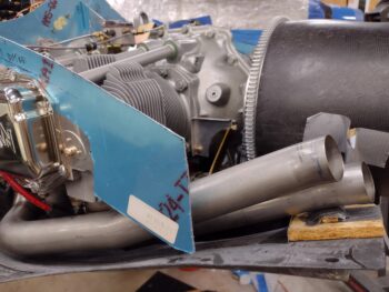
Well, after 2 days of missed delivery attempts from FedEx, I finally got the engine inner baffle molds delivered and in my hands.

I unboxed all the molds and did an inventory to make sure I had all I needed.  I was a bit confused at first because I didn’t see the top outboard inter-cylinder baffle, but after a few hours I had a bit of an epiphany and realized that you need to make another pair of each of the front and aft side cylinder baffles, merge those together and then trim them to make up this top inter-cylinder baffle.

These forms were made to use a higher temp epoxy than I am using, although I am using a decently higher temp epoxy with the HTR-212.  I’ll remind everyone in a post I made a while back that our resident community guru, Klaus Savier, noted that CF engine inner baffles could be made with MGS-285 and slow hardener.  This stuff beats out even the MGS concoction.

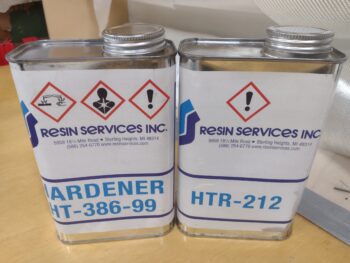
In addition, the high temp epoxy used on these forms was by design meant to have the inner baffle CF layups cured right on the form, using wax, PVA mold release, et al.  I specifically chose the HTR-212 high temp epoxy since it cures at room temperature, and doesn’t need to have the layups cured on the forms.

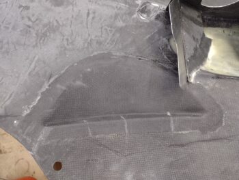
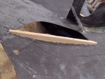
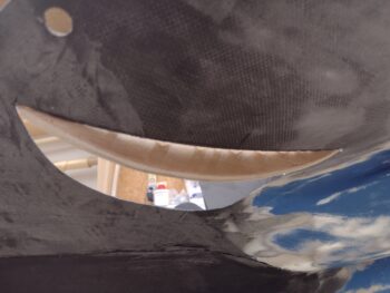
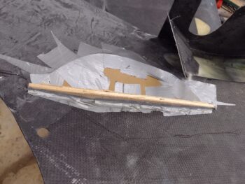
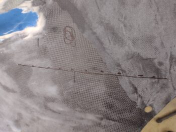
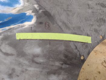
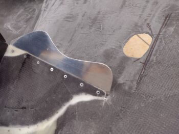
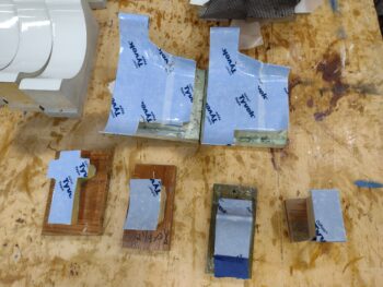
This of course creates another challenge in protecting the forms from the layup, which then entails a rather time consuming tape-up job for each form… but nonetheless that is what I did: starting first with blue painters tape, and then covering that with Tyvek house wrap tape as a mold release.

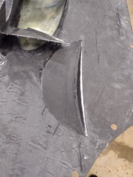
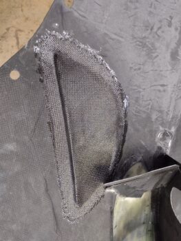
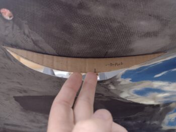
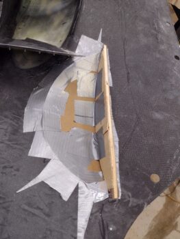
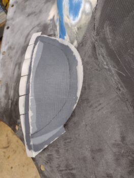
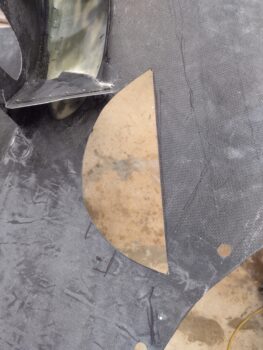
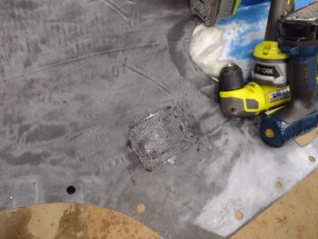
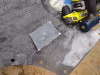
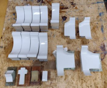
I wanted to get some parts laid up, since clearly there are a lot of them!  Round 1 consisted of the larger cylinder baffles that go on the front of cylinder #4 and the aft side of cylinder #1, respectively.  These were the trickiest to tape up so I wanted to get them knocked out.  In addition, the smaller pieces only have one form, and 2 parts from each form are required so I wanted to get the first round on these knocked out as well.

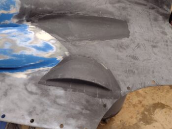
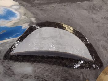
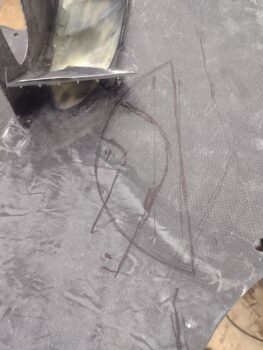
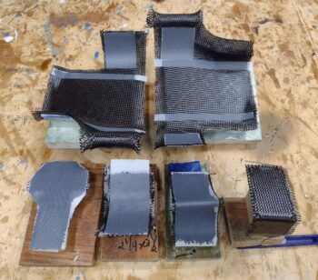
After taping up the forms, I then cut out 2 plies of CF for each part and laid them up.  As par usual, I’ll be modifying these inner baffles to meet the specific requirements of my engine.  I also plan on following some of the guidance laid out by both Mike Melvill and Andreas Christou on their implementation of engine baffles to optimize air flow and thus cylinder cooling.

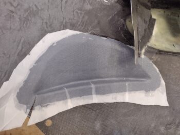
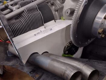
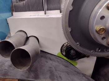
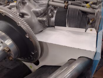
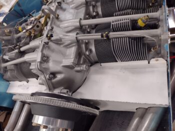
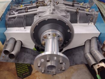
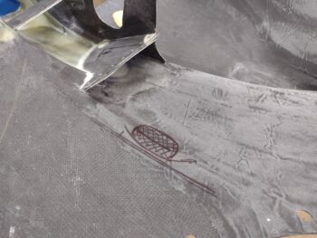
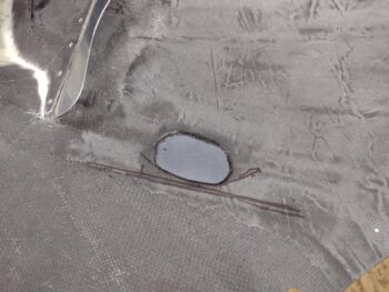
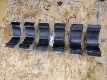
After a short dinner break I headed back out to the shop for Inner Baffles Round 2. This time the focus would be on the inboard baffles that go around the cylinder bases (closest to the crankcase).  Here we have 6 cylinder base baffle forms taped up with blue painters tape.

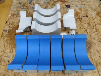
My plan was to tape up all 8 (2 per cylinder) and get those laid up, but between 2 of them having a “pimple” in the middle area of the form and the fact that it was taking so darn long to tape them up (and getting late!), I decided to just knock out 6 —3 pairs— of the cylinder base baffles.

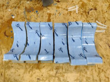
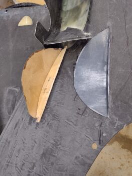
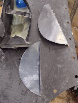
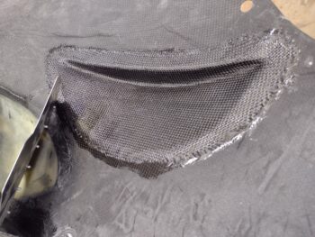
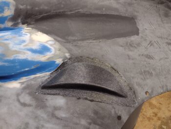
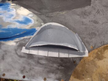
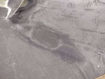
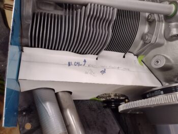
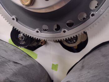
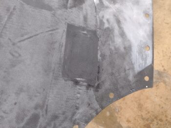
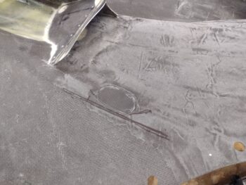
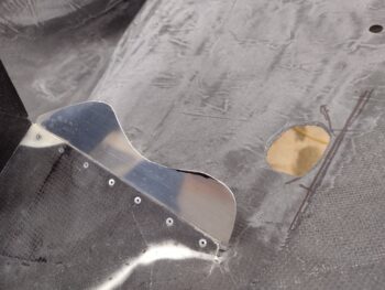
Here they are a good hour plus later after I cut and laid up 2 plies of CF on each one.  I cut up scrap pieces of peel ply and then applied 3 strips to each baffle segment for the subsequent attaching of these baffles to the cylinders with RTV (Toyota #103 is recommended, so I ordered some).

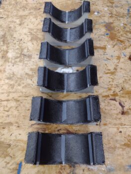
Here we have another shot of the 3 pairs (out of 4 total required) inboard cylinder base baffles 2-ply CF layups.

I’d say I got roughly half of these inner baffles “glassed” up tonight, which is pretty darn ok in my book.  Tomorrow I’ll knock out a good bit more.  I will note that the weather is getting cold so I cranked up the shop heaters and will need to keep heat lamps on these laid up baffles for their ~24 hour cure.

Chapter 23 – Right cowl wrap-up

I didn’t get a lot done today in the shop since I was getting ready to spend another good portion of the day/evening in New Bern watching the AeroShell Aerobatics team do their stuff (excellent by the way) and then a dinner out.

I did get the peel ply pulled off the bottom cowl right inside single CF layup for the aft/inboard exhaust pipe clearance bump, and a decent bit of cleanup done on that.  This of course being the final step for this bottom cowling clearance task as well.  The only requirement remaining is for a cross cowl stiffener that needs to be glassed in on the bottom cowl to complete all these niggling bottom cowl tasks.

I did actually buy some stuff, primarily for the wing light installs: I put in an order with ACS for a 24″ x 24″ sheet of 1/16″ plexiglass, cut in 6 each 8″ x 8″ pieces.  Concurrently I put in an order with McMaster-Carr for some hardware and the 3/8″ diameter 6061 aluminum rods that I’ll need for mounting the wing light assemblies into the wing leading edge pockets.

I then went downtown and picked up a cheaper toaster oven to heat up the wing light lenses.  Since acrylic off-gasses some nasty chemicals when it gets heated up, I didn’t want to work the wing light lenses in my kitchen stove.

Unfortunately, while I was out buying the toaster oven for creating the wing light lenses, that’s when FedEx stopped by to deliver the package containing the engine inner baffle forms.  I didn’t realize that I would need to sign for them, so I missed the delivery and won’t be getting them now until Monday (sigh).

I of course have a myriad of things that I can work on, and again, starting tomorrow I plan on jumping back onto the build whole-hog.

Chapter 23 – Final on clearance bump

I started off today by pulling the peel ply on the external 2-ply CF layup on the bottom cowling right side aft/inboard exhaust pipe clearance bump.  I then cleaned up the layup a bit.

I then pulled the taped-up cardboard and wood forms from the inside of the CF layup.  Here are couple of shots of the inside and outside of those forms.

I then pulled the interior peel ply off the 2-ply CF layup and cleaned all that up a good deal.

I then took a break for a few hours to head out for some face time with some Canardian buddies!

You see, last night while I was at Jess’s house for Thanksgiving dinner I got a call with both Mike Beasley and Marco C. on the line.  They both wanted to take a quick scoot in their planes and meet somewhere for lunch, and asked if I was available to meet them today at the New Bern airport.  Which I certainly made time for!  Jess and I met Mike and Marco at the airport and then we all headed downtown New Bern to walk around a bit and grab lunch.  It was great seeing those guys for a few hours before they both headed back home —in different directions: Mike south to Georgia and Marco north to Virginia (Thanks guys… good times!).

Back in the shop for a couple of hours I sanded down the bottom cowling edges around the right side aft/inboard exhaust pipe clearance bump opening with the cured 2-ply CF layup on the exterior side.  I cleaned up the fresh layup around the edges and ensured there was a good transition for an internal 1-ply CF layup, which I then knocked out next.

Another shot of the 1-ply CF layup on the interior of the bottom cowling right side aft/inboard exhaust pipe clearance bump.

I then peel plied the internal 1-ply CF layup.

I should be getting the engine inner baffle molds tomorrow and plan on starting in on those ASAP, although I will be heading back to New Bern tomorrow afternoon with Jess and some friends to watch an airshow and then out to dinner.  So most of tomorrow will be more social duties calling.  I do plan on getting back onto the build full bore from Sunday moving forward.


Chapter 23 – Right cowl “update”

Happy Thanksgiving everyone!  Yes, even those of you who don’t celebrate the holiday (you know who you are!).

Well, I am THANKFUL that I was able to get a significant task knocked out today: the initial layup on the lower cowling right side aft/inboard exhaust pipe clearance bump.  Again, this is the LAST of the clearance bumps, divots, channels, etc. that I plan on doing at this time, or see any further requirement for!

As I said in yesterday’s post, it was too late to make up a wood template/form last night, but that was the first and only thing on my list today —ok, and hot-gluing it into place— before heading over to Jess’s for a wonderful Thanksgiving feast! (All Keto too! Thanks Hon!).

I used my same Metal Brake crate for cutting out this form with my saber saw before then trimming and shaping each end a bit to allow it to fit snugly into place.  After I got it all situated, I then hot glued it into place.

Here’s a lower external cowl shot of the wood vertical “smile” form hot glued into place.

And me checking the original cardboard template against the hot glued in place wood form.

I then finalized the shape of the flatter, horizontal surface-taped cardboard form that I then hot-glued to the wood form’s bottom edge, and then taped into place everywhere else.

An outboard-in shot of the flatter, horizontal surface-taped cardboard form in place.

Again, in my haste the one thing I failed to take into account when making up the initial vertical cardboard “smile” template and subsequent wood form was the overlapping horizontal thin cardboard form on the bottom edge… that, and then add a couple of plies of tape and then even a ply of peel ply over that.  That all served to add a good 0.1″ depth to this clearance bumpout, which obviously was not as much as I was planning on.

Oh, well… moving forward.

I was on the phone with my son when I kicked off the actual layup and forgot to grab a shot after I had prepped the surrounding CF for layup and of the form taped up with gray duct tape.  Here it is after I wetted out the entire layup area and then added peel ply to both the vertical “smile” and curved horizontal parts of the exhaust pipe clearance bump.

I then laid up 2 plies of CF that I had cut previously (along with the pieces of peel ply).  Although a hair more pronounced than I was aiming for, the bump itself is looking pretty darn good (IMO).

I then of course peel pied the 2-ply CF layup.

And another shot of the peel plied 2-ply CF layup on the external bottom cowling right side aft/inboard exhaust pipe clearance bump.

I’ll also provide yet another reminder that for the sake of saving time and effort, I’m shamelessly copying Klaus Savier in his bottom cowling clearance bumps for his exhaust pipes.  I’m betting Klaus probably got this about as close to correct as you can get.

Now, that being said… I’ll note the beginning state of my bottom cowl surface is both significantly more sloping/angled inward (not horizontal as his is) and curved fore-aft where I placed my “swooshing smile” type bumpout.  The bottom line is I think my clearance is a bit more pronounced than his is due to the starting bottom cowl characteristics.

Nonetheless, the exhaust pipe bumpout that I just laid up should serve its purpose for providing needed clearance and that’s all that matters at this point!

Pressing forward….

Chapter 19/22/23 – Right pipe jam

I started off today by removing the bottom cowling and finally pulling the peel ply and cleaning up the left inside bottom cowl exhaust pipe clearance depression CF layup.  Now this task is officially done.

Before removing the bottom cowling I had outlined the right inboard exhaust pipe at the elbow, which is where a clearance issue still exists between this area of exhaust pipe and the bottom cowling.  I have double and triple checked all the other exhaust pipe-to-bottom cowling clearances for all the pipes and the rest are good.  This is the last bottom cowling clearance issue that I need to resolve.

I’ve pondered over the last few days of how I was going to resolve this right aft/inboard exhaust pipe clearance issue with the bottom cowling, even considering cutting the pipe and angling it upward a bit, but finally decided to work the cowling vs the exhaust pipe. I’m gong to plagiarize here and copy Klaus Savier’s design for bottom cowling exhaust pipe clearance by creating a slash-type bumpout with a sharp angle along the edge… specifically along the lines of the inboard slash-type bumpout shown here.

With the bottom cowl off I determined what was a straight line for the sharper vertical edge of the clearance bump by going off the leading edge of the bottom cowl, which I assessed as near to exactly perpendicular with the aircraft centerline.  After marking the outboard straight cut line on the inside of the cowling, I then drilled a tiny hole at each end of the line and pressed rivets into the holes.  I then flipped the cowling over to draw a straight line between the rivets for my proposed external cut line.

I then temporarily remounted the bottom cowling to check my cut line to see if it was actually straight and parallel with the aircraft’s centerline.  It looked fairly straight, but being on a curve it looked like it leaned out a bit.

I set up the laser level and with the laser line hitting the two rivets I determine the laser level was 16.75″ away from the center of the prop hub (pic 1).  I then placed a clamp sticking outboard at F22 and dropped a plumb bob at 16.75″ out from F22’s centerline.  I then lined up the laser line by moving it a smidge so that it hit the two rivets and the far plumb line (pic 2).  I then marked the straight laser line with dashes between the 2 rivets.

Fun with geometry!  Although the starting and ending points (the rivets) are in the same spot, a straight line over this curve is just a hair off from my original “straight” line (the solid line).

I started to use a piece of tape to mark the cut line, then just said ‘screw it’ and simply used the tape to cut the line.  Now, before I cut out the clearance hole I used a multipoint shape tool to capture the curve to make a template of the outside vertical edge (“smile”) of the clearance bump/divot.

I’ll note that the house next door to me was owned by an elderly couple that very occasionally would come down to stay for short lengths.  They sold it to some people who are now living in it full time, so I don’t want to make crazy loud noises now when it’s late at night.  Since I needed to run to Home Depot, which is 45 minutes away, I wanted to get this loud cutting done so I wasn’t doing it later in the evening.

That all being said, here is the right side inboard exhaust pipe clearance cutout on the bottom cowling.  Again, to mimic somewhat how Klaus has his bottom cowl exhaust pipe clearance bumps.

I then ran out to Home Depot in my quest for 1/16″ Plexiglas for the wing light lenses, which they had listed as in stock on their website.  Well, it was in stock but it was made for picture frames and was somewhat translucent with objects only closeup being clear.  I then ran to an arts and craft store and they only had 2mm (0.078″) thick acrylic in stock.  No joy.

When I returned home later in the evening, I spent about an hour cutting out the clearance bump/divot’s outside vertical edge (“smile”) template from scrap cardboard and creating the other horizontal part of the mold as well… assessing how I was going to do this layup the whole while.  I had planned on using the vertical cardboard template as part of a mold to layup the outside plies of CF first for this clearance bump/divot.

I then realized that the cardboard was too weak: not as a form, but in getting it as a free standing form to attach securely to the bottom cowling for the layup.  It became clear rather quickly as I started my attempt to make a form on the bottom cowling that I needed to transfer the cardboard template to thin plywood.  And it was way too late to start that, so I kicked that can down the road until tomorrow…

So I closed up shop, went inside and did some more research on cast vs extruded Plexiglas… and then spent a good bit of time looking for vendors that had that darn elusive 1/16″ acrylic/Plexiglas in stock!

Moreover, in case I don’t get a blog post in tomorrow: Happy Thanksgiving everyone!

Chapter 19/22/23 – More on wing lights

This blog post covers yesterday and today.  I had some personal stuff to do as well as a number of build related phone calls and research to do.

I started off the day with a conversation with GRT Avionics regarding compression fitting EGT probes to ensure that if I needed to go that route I could integrate the ones they sell in with my current set of probes.  As I thought, I can with no issues.  I also asked them how I would go about actually and specifically mounting their compression fitting EGT probes to my pipes: the bottom line is that I would need to acquire/provide a 1/8-NPT female threaded bung/fitting to then weld onto the pipe to secure the compression fitting EGT probe into.

I also asked Nick Ugolini what thickness of aluminum he used for the wing light mounting plate, to which he replied that it was very thin, about 0.015″ thick… obviously to save weight but also since there is no major stress on the mounting plate from these thin, lighter-weight light assemblies.

I was out and about picking up some hardware to test out on these light assembly brackets when I got Nick’s above reply.  I then pondered on it more as I ran my errands —including picking up the light lens plexiglass/acrylic at Lowe’s (they only had 0.080″, so I’m going to try Home Depot and/or some other places within the next day or two for some thinner 0.065″ plexiglass)— when it occurred to me that I might just press forward with using ABS plastic for the lens light mounting plates/brackets.  Hmmmm?

When I got home I started doing research on the best ways to heat and form plexiglass, as well as brushing up on my Fusion 360 CAD modeling kung-fu skills in creating hexagon grids for what my current mentally-pictured bracket looked like.

Now, Fusion 360 is obviously a powerful CAD/CAM/modeling program, but I equate it to a lot of other technical skills… very perishable.  If you don’t do it often your skills definitely atrophy.  Moreover, seemingly simple tasks like adding a side grid of hexagons shouldn’t be that difficult, but it took me deconstructing the info in about a half dozen videos and then over 2 actual hours to hamfist my way through.  But I figured it was another good tool to have in my CAD toolbox, so I “wasted” a few hours in figuring it all out.  Here’s the result after a nearly 3 hour print:

I put 0.6″ deep sides on the wing light mounting plate to reinforce the plate.  I guess now it’s more like a “bracket.”  Whatever you want to call the darn thing.  The hex grid is to ensure cooling air is free and unhindered to the light cooling fins, as well as to significantly lighten up the bracket of course.

And here’s a side shot of the hex grids on the new version of the wing light mounting bracket.  My plan is to make up a final version of this bracket and then machine an aluminum mounting plate to see if there is any significant weight difference, and then press forward from there.

If you’re wondering, Nick already did the heavy lifting on the heat generated by these lights inside the small leading edge wing pocket by doing a multi-hour long burn-in session with the light in the wing pocket and the lens taped in place.  He noted with the LEDs it was a bit warm, but nowhere close to any issue with high heat.

I also queried Nick on the steps he used to heat, mold and create the acrylic lenses.  He replied that it had been so long ago that I should ask Chrissi and Randi (AKA “The Cozy Girrrls”) about it since they just did this fairly recently.  So I did.  That kicked off about a 1.5 hour long phone call with Randi, with no appreciable new Intel in hand by the end of the call… although it was great catching up and discussing all things Long-EZ!

Finally, I’ll note that I had a quick discussion with my contact regarding the inner engine baffle forms, and I’m happy to report that they are being shipped to me (I have the tracking #!) and I should have them Saturday.

Now, that being said… for all you foreigners (ha!) this week is our American holiday, Thanksgiving.  Between that, a 2-day out of town trip and an airshow/dinner evening out, I’ll have quite the social calendar going on over the next 4-5 days.  I do plan, however, on getting what I can done on this bird when I can during that timeframe.

Pressing forward!

Chapter 19/22/23 – Back on Baffles

Today was all about the initial big push to get the aft engine baffle templates dialed in for my engine in prep for when the inner baffle forms arrive and I get those knocked out and installed.

I started on the left side and cut Mike Beasley’s “Beasley Baffles” template at the long corner edge of the upper “shelf” section and the lower “skirt” section.  I used the upper shelf section as is and trimmed it to fit.

On the lower skirt section I made a copy of the original template on a large piece of poster board and then used that to make my template on my engine.

After I dialed in the left side top shelf section and the bottom skirt section, I simply taped the 2 pieces together.  All in all, with the constant iterations of putting the templates in place, marking, trimming, putting back in place… rinse and repeat… it took me well over 2 hours just on that part alone.

But I am definitely much, much closer to a finished product, albeit with a myriad more tweaks and trimming left to do.  This is merely the first stab at getting an initial workable template for the aft baffle segments.

I then repeated the same thing on the right side.  Again, this took a good couple of hours to do the initial skirt baffle copy and then slowly dial in the shape and form of the right aft engine baffle.  Note that I actually had a little help on this side with the screw hole in the #2 cylinder head.

Here’s a shot of the engine aft baffle “shelf” sections.  I’ve seen this baffle style in a lot of pushers where the aft corner edges of the shelves match, even though clearly the right shelf —with the cylinders positioned forward— is much wider than the left side.

The area beneath the flywheel, around the alternator and starter, is typically much wider, deeper and bowl-shaped on other Long-EZs than the “V” shape that the Melvill cowling has… regardless, it all seems to fit so I’m happy with it.

And here we have both poster board/thick paper aft baffle mockups in view.  I really like the way this will look when completed.  That being said, I have to note that both sets of exhaust pipes are kicked out a hair more than they will be when all the component installs are final.  Thus clearly why I’m dialing these aft baffle templates in with poster board so I can tweak, modify and dial in as required.

To get an idea (for me and you!) of how this will look with both the spinner flow guide and upper cowling in place, I went ahead and temporarily put both in place.  As each step progresses and each task is completed on this engine area, I’m more and more pleased with how it’s all turning out.  It honestly was not a fun first half of this year figuring and working it all out.

And with all that good feeling talk, I should note that I’m going to have to make a significant cowl bump on the RIGHT side bottom cowling under the horizontal elbow of the right inboard/cylinder #2 exhaust pipe.  It’s just too close to the inside corner of the bottom right cowling.

These pics give you an idea of what I’ll be looking at during pre-flight when I check out the alternator and belt on the left side and the starter on the right side.  Yep, even though the cowlings are very tight around this engine, I still have good visibility to check on these components pre-flight.

I had texted Nick Ugolini earlier in the day that I was ready to discuss the wing light forms that I received from him (as well as a slew of pics).  We agreed to discuss my wing light install later in the evening.  Well, perfect timing on Nick’s part because he called tonight just as I was just winding down in the shop.

Nick and I were on the phone for well over an hour discussing primarily his how-to steps on installing the outboard wing landing and wig-wag lights.  In addition, we spent a good little bit talking about baffling and engine cooling.

If you’re not familiar with the outboard wing leading edge lights, here’s what they look like when the install is complete:

Although it was late, my curiosity got the best of me and I measured up one my AeroLEDs “Recognition/Landing Light Assemblies” to model up a light support bracket for mounting into the leading edge of the wing.

I then of course did a quick 3D print of the wing light bracket.

Thankfully my numbers were correct, and the light fit like a glove in the 3D printed test light bracket.

And a bit closer final look . . .

Like I said, it was late… so with an unplanned task knocked out, I hit the rack.

Chapter 23 – EGTs on deck!

Today was primarily about getting the exhaust pipe EGT probes positioned and installed, but first I pulled the peel ply off the bottom cowl left side outboard exhaust pipe clearance depression 2-ply CF layup.  It looked great, so I moved to the inside…

Where I pulled the peel ply on the inside of the divot that I created on the left side of the bottom cowling for the #3 cylinder exhaust pipe clearance (I forgot to grab any pics of the ensuing 1-ply CF layup and peel ply on the inside bottom cowling, but you can catch glimpses of it in the pics of the cylinder #3 exhaust pipe EGT probe immediately below).

I spent well over 2 hours in my final research on EGT probe position (facing inboard or outboard?), placement (how far from exhaust pipe flange?) and any other general tips and/or tricks that I could find.

If possible, EGT probes should all be equidistant from their respective exhaust pipe mounting flanges to all be reporting their equivalent heat value at the same distance from the heat source (aka “the exhaust port’).  Makes sense.  That being said, I also noted the oft warning of having the EGT probes mounted too close to the exhaust flange/port and risk literally getting burned up, drastically reducing probe life.  The sweet spot reportedly is around a 3″ EGT probe position from the exhaust mounting flange, which is inline with GRT’s recommendation of 2-8″ as denoted in their EIS install manual.

It took a good half hour to find a compromised sweet spot between all the exhaust pipes, the aft cylinders being the odd ones out requiring special attention here.  The common EGT probe install position/distance I settled on for all cylinder exhaust pipes was 2.65″ from exhaust flange face to EGT probe hole.  For added measure I’ll throw in a swag of +/- 0.15″ max… but probably more like +/- 0.07″ in reality.

Here we have the left outboard/cylinder #3 exhaust pipe EGT probe hole drilled (pic 1) and installed (pic 2).

And here on the right side, we have the inboard/aft cylinder #2 exhaust pipe EGT probe hole drilled, with the EGT probe installed on the outboard/forward cylinder #4 exhaust pipe.

Here I’ll quickly note another oft-cited warning that various homebuilders provided: ensure not to block access to installing or removing the bottom spark plugs.  Yes, good thing to watch for!

Again, the aft cylinders needed some special consideration not just in the distance between the exhaust pipe flange and the EGT probe, but also in the clocking of the probe —which I really haven’t touched on yet, but was a significant consideration for each individual probe— not only in regards to what angle the EGT probe body was protruding from the exhaust pipe, but specifically the placement of the securing hose clamp screw assembly.

A perfect example of what I’m talking about is the right inboard/cylinder #2 exhaust pipe: if the hose clamp screw assembly is positioned forward, approximately 90° from the EGT probe (as they all are; standard position) as in pic 1, then it results in diminished clearance for that exhaust pipe as a whole with the bottom cowling as you can see in pic 2.  Since I have just a hair under a 1/2″ worth of clearance between cylinder #2’s exhaust pipe and the bottom cowling, clearly the hose clamp screw assembly in this position diminishes that clearance greatly and is an outright no-go.

The problem then potentially becomes about as much of a pain in the keister as well if I place the hose clamp screw assembly 90° out on the other (aft) side, since it starts clogging up the access to remove or install the #2 cylinder bottom spark plug [Ah, which I was warned to watch out for!].  But I will note that I didn’t test out this possible clearance issue, but will tomorrow….

Yep, I jumped the gun on checking clearance for the left inboard/cylinder #1 exhaust pipe EGT probe by mounting the bottom cowling in place, so again I’ll have to check spark plug removal/install clearance on cylinder #2 tomorrow.

That being said, here we have the EGT probes installed on the right side exhaust pipes.

One last note on the possible clearance issue with cylinder #2 spark plug removal/install and the exhaust pipe EGT probe hose clamp screw assembly… IF that proves to be an issue the fix would be installing a compression fitting style EGT probe.  That would require welding in a threaded port at the EGT probe position on the exhaust pipe, then sliding the EGT probe in position and threading in a securing cap that is pre-installed around the EGT probe assembly.   I would of course need to order this type of EGT probe from GRT:

Additionally, if possible I wanted each cylinder exhaust pipe EGT probe to face inboard towards the engine to allow for better routing of the EGT probe wires.  Being very low voltage signal wires I wanted these EGT probe wires as far away and not comingling with the much higher powered spark plug wires in any fashion.  However, I was only able to face the #1 cylinder exhaust pipe (aft left) EGT probe inward, with all the remaining facing outboard.

And as it just so happens, the final EGT probe I installed was on cylinder #1.  Again, I didn’t want the EGT probe hose clamp screw assembly facing downward since this would eat up exhaust pipe clearance with the bottom cowling.  On the top side I didn’t want the hose clamp screw assembly too canted inboard since I didn’t want any ensuing clearance issues with the cylinder fin baffles that will go in this area.  In short, I wanted the EGT probe hose clamp screw assembly situated squarely on top of the exhaust pipe, with the EGT probe itself facing inboard and positioned slightly downward… pretty much just like it’s shown here:

Here we have the EGT probes mounted into the left side exhaust pipes.

Finally, as I prepared to close up the shop for the evening, I went ahead and set the top cowling in place to check out the positioning of the left exhaust pipes in the aft cowling opening.  Pretty not bad IMO!  The pipes of course need to be trimmed in length and their final openings will both be about 1/2″ inboard (right in pic).

And with that, I called it a night!

Chapter 23 – Measure 7x, cut once!

I started out today by removing the bottom cowling, then spending a fair bit of time assessing and evaluating just how and where I needed to cut the left outboard exhaust pipe to get the aft half into its proper position.

After finally deciding where I needed to cut it and on what angle, I marked the cut line.

I then removed the left outboard exhaust pipe and ran a piece of tape with the edge at the center of the cut.  I then marked the angle on each side of the center cut line that in my estimation would bring the aft end of the pipe down close to level with the front end, and allow it to pair up decently with the inboard exhaust pipe.

As you can see below, I then carefully cut the pipe on the angled lines off the marked center cut line.

I then taped the left outboard exhaust pipe pieces tightly together at the cut… Voila! Pretty darn close to where I wanted it!  To be fair, I was trying to get it about an 1/8″ higher so this pair of pipes would be angled more like the right side pipes.  But no worries, this will work!

As a reminder, this is close to what it looked like when I started.

And a side shot of the cut and tape re-joined left outboard exhaust pipe.  This definitely meets my overarching goal of getting the pair of left exhaust pipes positioned at the correct elevation inside the cowlings and somewhat closely nested together.

And again, this is what the pipes looked like just before I made this cut.

I also took the opportunity tonight to add a little depth to the bottom cowling at the point where the left outboard exhaust pipe first major bend is closer to the cowling… at the hash-marked area.

I cut out the hash-marked area with the Fein saw.

Now, the key to understanding what I’m doing here —very hard to show in pictures— is that there is an upward indention from the outside of the bottom cowling from where I reworked the aft half of the bottom cowling.  This creates a bit of ridge on the inside of the cowling, which is right beneath the initial bend of the left outboard exhaust pipe.  I’m essentially removing that inside cowl skin ridge and flattening it to get a good 0.1″ minimum added clearance for this area of the exhaust pipe…. probably a hair more than 1/8″ in total clearance.

Also, if you look closely on the aft aluminum vane outboard edge you’ll see a Sharpie mark (pic 1)… this is the edge that needs to be trimmed just a hair (also for clearance with the left outboard exhaust pipe), which I did with the Dremel tool and then cleaned up the edge with some files (pic 2).

I then prepped the exhaust pipe clearance hole in the bottom cowling for a layup.  I measured and cut 2 plies of CF, prepregged them, and then laid them up with some MGS epoxy.

I then peel plied the exterior side of this 2-ply CF layup.

And also the exposed CF layup on the inside of the exhaust pipe clearance hole.

Tomorrow I’ll pull the peel ply, smooth out the edges of the existing cowling surface around the new CF layup, and then layup a ply of CF on the inside of this bottom cowl exhaust pipe clearance layup.

I’ll most likely get the outboard exhaust pipe welded up either Monday or Tuesday, so between now and then I’ll get to work on some other stuff!  Pressing forward . . .


Chapter 23 – Another pipe welded!

Today was another exhaust pipe welding day.  I loaded up my vehicle and made the hour trek to James’ shop to the get the inboard left exhaust pipe for cylinder #1 welded up.

As I said in yesterday’s blog post, this was a 2-weld job since the exhaust pipe at this point was in 3 segments.  Here’s a shot of these segments on James’ workbench ready to be welded up.

And here is the inboard left exhaust pipe —both sides shown— many hours later back in my shop after James’ excellent job of welding it up.

The sharper initial curve angle, that I had discussed with both James and Clinton from Custom Aircraft Parts (original builder of these exhaust pipes), is required for clearance of the pipe off the bottom cowl.  It looks even sharper because the curve on the original exhaust pipe continued downward for a good 1/4″ or more before coming back up level… that’s why that small segment of straight pipe had to be welded into place at a sharper angle: to replace the downward curved section.  The angle will have negligible, if any, negative impact on the exhaust flow.

Here is the freshly welded left inboard cylinder #1 exhaust pipe mounted in place on the engine.

And here’s a shot of that pipe from below… the sharp bend now being the low point vs the pipe segment 2-3″ aft of that bend.

I then put the bottom cowling back on to check the elevation of the welded left inboard exhaust pipe compared to what I was looking for.  As you can see, the pipe is just kissing the wood spacers that I had taped in place for where I wanted the aft pipe edge to be (pic 1).  I then removed the wood spacers to show the gap without them (pic 2).

I then spent another hour assessing both the clearances between all the pipes and the bottom cowling and EGT probe positions.  In addition, I also assessed what needs to happen now with left outboard pipe to angle it down and inboard to nestle it in with the inboard exhaust pipe.

On clearances: I decided I won’t need the significant bump out or divot in the bottom cowling for the outboard left exhaust pipe as I thought, since it sits right on the seam from the old cowl surface to the new cowl CF that I reworked.  By just reworking the seam I should get about another 0.1″ of clearance without have to make any notable bump on the exterior side of the cowl.  However, the initial elbow on the right inboard exhaust pipe is even closer than this cylinder #3 pipe, so I will need to flush that out and assess further.

At this point my brain was hurting from so much thinking, so I called it a night.