Hurricane Florence Extraction Operation

Well, what seems to be the norm in my build —and anyone else’s build admittedly— I had to engage in the proverbial “two steps forward, one step back” as Hurricane Florence loomed towards the coast of North Carolina.

Since I had already turned off my cable service to my house in Northern Virginia in prep for the upcoming move (and to save money) I was blissfully ignorant of Florence’s maniacal intentions until my buddy Greg texted me and asked me what I thought about “Florence.” I thought I must have forgotten some discussion we had on his vacationing in Florence (Italy?).  Upon Googling it I then became one of the watchers-n-waiters to see what would happen.

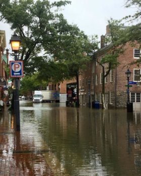
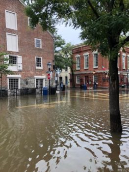
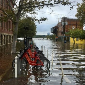
And it just so happened that on Monday evening I had plans to head up to Old Town Alexandria for happy hour and dinner with some real estate agent friends of mine.  I got a text about an hour before heading out that we couldn’t go to our usual haunt since it was under siege by a couple feet of flood water, along with the rest of the Old Town waterfront a couple blocks in from the Potomac River.  (“Uh-oh” I thought, “if this thing is already impacting us this far north, I need to take heed!”)

I immediately called Sunbelt Rentals to see if they had my trailer available for rent, which they did. [BTW, this location happens to be one of the very few out of all their locations that has a trailer wide enough to accommodate the width of the main landing gear].  Since it was right before their closing time, and I still didn’t have an exact update on what Florence was doing, I decided to hold on off on reserving the trailer.  In addition, they open at 6 AM so I could grab it right at opening time if need be.

After dinner I got a Florence update and heard of the non-mandatory evacuation by noon Tuesday, I decided my mission was most likely a go.  I set my alarm for 5:30 AM (Tuesday) and headed off to bed.

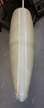
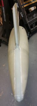
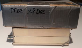
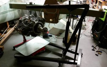
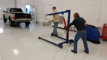
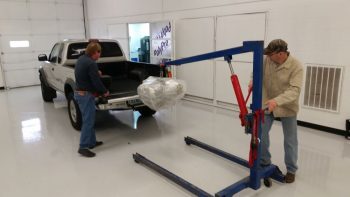
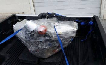
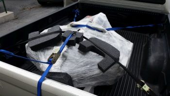
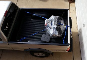
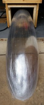
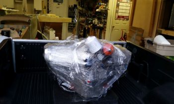
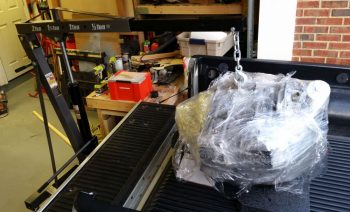
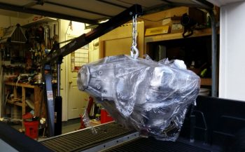
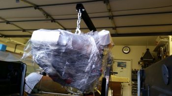
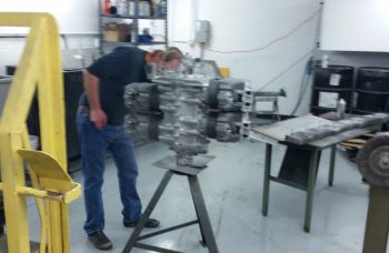
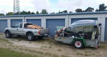
By the next morning it looked very likely that Hurricane Florence was going to hit the North Carolina coast very near my storage unit.  Thus, my fuselage rescue and evac mission was a go.  I got to the rental location just after 6 AM and rented the trailer, did the paperwork, and got it hooked up.  I was then on the road just a bit after 6:30 AM, and arrived my storage unit just before 1 pm.  It took me about 5 hours to load up my motorcycle, fuselage, wing, and miscellaneous expensive stuff (including the baggage pods, wheel pants and my main avionics box!) before heading out of there about 6 pm.

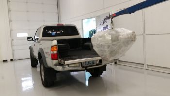
As you can see a bit in the pic below, the weather was beautiful on Tuesday and hard to believe that a hurricane was bearing down on that location.

I then scooted over towards the west side of NC and went to Greensboro for a couple of days, offloading a few things at Stacey’s house before taking off at 3:30 AM Friday (14 Sep) to head north towards home.  For the most part, I had been able to keep the unpainted airplane components out of direct sunlight, so wanting to drive while dark and avoid traffic was my main reasons for leaving so early.  As it turned out, it was a perfect time to depart Greensboro.  I hit 10-15 min of heavy rain just west of Raleigh and maybe a half hour on each end of very light rain, but for the most part it was a dry trip and the fuselage was fairly water free upon my arrival home around 8:30 am.

My friends from the Cherry Point, NC area had also traveled over towards Greensboro and stayed in a hotel, and then followed behind me a couple of hours heading up to my place in Northern Virginia.  It was great having them for the week and a half that we waited out Florence’s shenanigans and ascertained what damage she had wrought.  They then departed on Saturday, 22 Sep.  Needless to say, their visit slowed me down considerably on my house updating efforts in order to prep it to sell.  Moreover, Marco was in town the following Monday (24 Sep) for training and stopped by for quite a few hours to talk shop and have dinner at a Peruvian chicken place that I turned him on to.

During Marco’s visit we discussed Rough River with the underlying assumption that I wasn’t going.  Marco’s Long-EZ is down for engine repairs and he was making plans to fly over to RR with an EAA chapter buddy in his Velocity.  However, after a few “check” flights it turned out that the Velocity was having some avionics issues and needed some tweaking before flying any instrument approaches.  Thus, I got the call just a couple of days later (Wednesday) that Marco was driving to Rough River and really wanted a wing man to come with during the 12+ hour drive there . . . so, not wanting to leave a buddy high and dry, I decided it was acceptable to take a few days off for RR.  Details of the RR trip are covered in the next blog post . . .

[BTW, I learned from both my friends returning back to NC and the owner of the storage unit that miraculously there was no flooding at the storage unit and all my other stuff made it through the hurricane unscathed!]

Chapter 23 – Camshaft bath time!

Today I carved out about an hour from house updating tasks to bake a couple of batches of desiccant to reinvigorate the moisture absorbing power of this magical stuff.

Part of that process was pulling the cylinder dehydrator plugs to replenish them as well with the high-octane desiccant.  I then replaced the freshly pulled dehydrator plugs with spark plugs and then flipped the engine inverted to bath the camshaft and upper areas of the crankcase with oil.

After I inverted the engine I then replaced the bottom spark plugs with the freshly replenished & renewed dehydrator plugs.  As I pulled the plugs on a couple of the cylinders I used a flashlight to take a peak inside the cylinders to check out the condition in there.  The walls and a bit of a piston in both cylinders that I checked were wet with oil and shining bright as a new penny ( . . . or maybe a dime, since it’s silver colored?!).

Happy with what I saw I tried my best to grab a pic of the cylinder wall, which you get a general idea of in the shot below.

I’m really happy with this engine stand and appreciate being able to get the camshaft soaking in a bath of preservation oil.

When I inverted the engine this time around, I made sure to run the output line from the engine dehumidifier into the cold air induction plenum opening, which I then ensured was as taped closed as possible (sorry for the not-so-clear pic!).

I also installed some Lycoming exhaust manifold port covers that I picked up from ACS. They cost a bit but I’ve been so busy –with no time to roll my own– that I went ahead and pulled the trigger on them. Also, as you can see, again I loaded up the dehydrator plugs with fresh desiccant.

[NOTE: At the very bottom edge of the pic below you can see a drop of oil near the clear tubing.  I found that the fuel injection nozzle port was dripping oil so I tried my best to tighten the fittings.  I got a little bit of the main fitting and good bit of the smaller fitting, and slowed the drip down considerably…. but I will need to sinch up the fittings a tad more to ensure the leaking is stopped.]

In addition, I threw away the tired desiccant packs that I had stuffed inside the exhaust manifold ports a while back and should be getting a batch of good-sized fresh desiccant packs within the next day or so to replace the ones I threw out.

I have been meaning to invert the engine for weeks now but of course had to deal with swapping plugs, refreshing the dehydrator plugs, baking desiccant, etc.  I’m really glad that I was finally able to get this done and all still looks spiffy-keen with the engine!


Chapter 19/23 – Baggage pod break

I took a short break this morning to pull the peel ply and clean up the edges of the major CL seam layup on baggage pod #1.

Later this evening I laid up a 4 ply pad of BID on the aft bottom end of baggage pod #1 that will serve to reinforce the lip for attaching the baggage pod aft cone.

I then laid up 3 plies of BID around the main CL seam on baggage pod #2 just as I did on the first baggage pod last night.  I then peel plied the layup.

While I was looking at some pics tonight I found a shot of the cowlings from around 2012 that had a document included that I haven’t seen in quite a while.  While looking for the document I finally completely unwrapped the Berkut-style armpit intakes for the lower cowling.  As you can see, I decided to grab a couple of shots of these to include in this blog post…

Again, with my house updating shenanigans I only have a couple of hours a day that I’m allowing myself to work on the plane build.  However, I figure every hour counts and gets me much closer to the finish line!


Chapter 13/18 – Canopy Wrap-up

To wrap up the nose build (so far), canopy build, and fuselage move down to North Carolina, I threw together a video to cover these topics.

I’m hoping this video will help shed some light on some of my build tasks that may not have been as apparent in my description using just pictures and words in my previous blog posts.

So, with that, I’ll simply say “Enjoy!”


Chapter 3/22/23 – Back at it!

I just returned from my North Carolina sortie late this afternoon.  I of course had to attend to some normal life stuff before getting back into the groove of things.

I would like to actually start out by reporting on a couple things I did/noted before I left for NC.  The first is that before I left out I flipped the engine inverted and recharged the cylinder dehydrator plugs with fresh desiccant.  Since I have 4 of the these dehydrator plugs I removed them from the top plug holes on the cylinders and replaced them with standard aircraft spark plugs before flipping the engine upside down. [This is a previous “stock” pic I took of the engine positioned inverted on the engine stand… it’s mislabeled stating that it was inverted only for a few hours vs 5 days].

After replacing the desiccant in the dehydrator plugs I then pulled the 4 standard aircraft plugs on the bottom of each cylinder (of course facing up at this point) and replaced them with the dehydrator plugs.  Since the oil filler cap was facing downward and the top mounted crankcase vent would leak into the Engine Dehumidifier air lines if I tried to attach it to the inverted engine, I just left both unconnected for the duration of my trip.

In addition, as I was packing up for taking a load of household stuff down to NC, I found my cardboard mockup of the Trig TT22 transponder.  It became readily apparent why I thought the actual TT22 unit was much smaller than I expected as I realized why when I compared the two.  The dimensions for the TT22 unit are given from the tip of antenna jack to the end of the wire mounting spring clip on the other end.  Clearly the box section of the unit is not included in those dimensions, making it much smaller in real life than my mockup.  Just an observation I had in how there always seems to be some sort of wrinkle in the planning of this stuff for the aircraft build.

So I got back home late this afternoon from NC and immediately kicked off an overdue Seattle Avionics chart data update for the GRT HXr EFIS (I missed the previous one… ).

In addition, the desiccant I left in the oven while I was gone was clearly saturated with moisture and had turned a bright light pink, so I fired up the oven to refresh the desiccant to its desired brilliant blue state.  A while later, after letting it cool a bit, I put it back into a sealed container to use in the Engine Dehumidifier after I flip the engine upright tomorrow.

Also upon returning home I found that some packages had arrived, including a digital tachometer and project box (to mount it in) from Ebay for the lathe.  Since I had to make a Home Depot/Lowe’s run I decided to do a quick check of the upcoming tach install to ensure I had all the components I would need on hand…. which I didn’t so I ginned up a list.  While I was at it I spent another 20 minutes mounting the lathe Quick Change Tool Post (QCTP) onto the lathe compound/cross slide/carriage.

Once the heights of the various lathe turning/cutting tools are dialed in, the QCTP will allow me to swap out tools in literally seconds vs tens of minutes.  Below are examples of a parting (“cut-off”) tool [top] and a turning tool [bottom], each in their respective tool holder [the attached tools are from a cheaper carbide tipped “indexable” tool kit I picked up from Harbor Freight, since it had good reviews…. I’ll use these tools as part of my kit starting out so if/when I break them during initial lathe ops, my cost of learning will be cheaper!].

Late this evening I did some final updates on my nose and canopy build task lists and printed those off in prep for starting back on these builds tomorrow.


Chapter 23 – Engine Pickling… MC

“MC” for those of you never having filed a travel voucher for an Air Force mission was always the last 2-digit code annotated and stands for “Mission Complete” . . . which is currently the status of my engine pickling endeavor.

I will note that with the big task of welding up the engine stand mounting brackets and seeing my buddy Greg off over a couple of nights really put a dent in my schedule, and put me way behind the power curve time-wise.  Since I had a locked in rental on a moving trailer, and a locked in timeframe that I needed to be in NC, my back was somewhat against the wall.  Still, the primary goal here for me was to get this engine pickled, and then move what I could in the allotted time I had left.  I just was not going to risk any internal engine corrosion with any more time than was necessary.  In short, it was time to get this engine pickled.

With having removed the engine last night from the fuselage, I then did the limited trial and error dance for getting the bottom engine stand mounting bracket mounted to the engine mount.

However, the top mounting bracket was the big dance, and it took a couple of hours to dial that baby in.  The primary issue was that I forgot how the engine mount stubs –and thus the engine mount extrusions– are at a slight angle to follow the fuselage angle (this is denoted in the plans).

After much wailing & gnashing of teeth, a number of expletives and my new boneyard of broken drill bits (I think one side of the mount ended up so hot that it was in an annealed type state… since drilling a hole into it was like going through stainless steel) I finally got it all put together and then the engine mounted to the stand!

Here’s a better view of the engine mount attached to the engine stand mounting brackets.

And a couple of views from the top.

Ah, yes, and of course here we have a view more from the lower side.

I also drilled a hole through the lip of the oil drain valve to accept a 0.041″ piece of safety wire.  I then threaded the oil drain valve in place.  Unfortunately I was remiss in remembering that this was a Japanese made oil drain valve, and thus metric, so my 3/4″ wrench was just a hair loose on it.  When I really went to snug it up that last little bit I rounded a couple of the wrench flat corners over.  I then grabbed a 19mm wrench to finish up the last little bit of snugging it up tight.

I removed the spark plug cylinder dehydrators from the bottom side of each cylinder and replaced them with standard aircraft spark plugs.  I then removed the top spark plugs while I squirted preservation oil into each cylinder, and then replaced them with standard aircraft spark plugs as well.

I sprayed approximately 2 oz of PolyFiber Engine Storage Oil (ESO) into each cylinder when its piston was in the down (inboard) position.  I will admit that I realized as I was prepping for the pickling of the engine that an optimum solution would have been to have cover plates for both the intake and exhaust manifold ports, but I didn’t have either, and again, since I was in a time crunch I pressed forward and simply placed an oil drip pan underneath the engine for any runoff.

I will say that I shown a pen light into each cylinder with the top plug out, and what I saw on the each cylinder wall gave me a huge sense of relief.  I could see the honing of each cylinder wall with bright shiny metal and NO corrosion…. which I’m very thankful for.

I then poured 3 quarts of Phillips 66 20W-50 oil into the engine, fed in the remainder of the ESO and then poured in an unused quart of Harley-Davidson 20W-50 to top it off.

With my 4+ quarts of oil in the sump, I then flipped the engine upside down and let it sit that way for a good 5+ hours as I loaded up my rented moving trailer.  My goal here of course was to bath the top-mounted camshaft in a bunch of oil.

In my haste I failed to cap the oil heat return fitting so it spit out a bit of oil when I flipped the engine upside down.  Beyond that little issue the engine stand seemed to work exactly as I thought it would in allowing me to wrench on the engine and also rotate it as if it were on an “engine spit.”

Before I left for NC I turned the engine back right side up and attached the hook of the engine hoist to the top engine lifting tab.  I’ll turn the engine back upside down when I return from NC, but since I just welded up the engine stand mounting brackets I didn’t want to test my luck (just in case).

I did leave a bit of a gap between the engine hoist hook and the engine lift tab to allow me to quickly identify if any of the welds on the engine stand mounting brackets gave way while I was gone…. again, just a precaution with an expensive aircraft component.

For the final push on the engine pickling, as I was working on the engine I was also concurrently baking up another batch of pink desiccant.  Once it had turned blue and cooled, I then recharged all the cylinder dehydrators and the main engine dehydrator bin.  I then removed the top spark plugs and replaced them with the spark plug cylinder dehydrators.  Note that now the spark plugs are mounted on the bottom of each cylinder with the spark plug cylinder dehydrators on the top.

Again, I’ll be gone for a few days, and with the engine now off the fuselage and pickled for the time being, when I return I’ll be putting all my energies into building the nose and canopy to finish off the aircraft centerline build.


Chapter 23 – Engine Build: Phase II

I started out this morning at around 0630, packed up the truck with all my engine accoutrements and headed off on my 1.5 hour trek up to Winchester, Virginia for the last phase of my engine build.  I had already talked to the builder, Tom, who let me know that during some down time in between engine builds that they installed the Superior cold air induction sump and the high pressure fuel pump, and sure enough that is exactly what I found when I arrived.

Here’s the high pressure fuel pump mid-picture, just to the right of the PMag ignition.

Here are a couple wider angle shots showing more of the Superior cold air induction sump.

Although it seemed they were eager to pack up the engine and for me to get it out of their hair, I did want them to finish installing the fuel injector nozzles, the fuel injector distribution spider (and bracket) and the 1/8″ stainless steel lines in between.  Another engine builder that I hadn’t met yet, Larry, undertook the task to hook up the fuel injection lines.

With the topside fuel injection components and lines in place, and after Frank I messed around installing, moving and reinstalling some AN fittings for the main oil line and the oil heat system return line, Frank and Larry then wrapped up the engine for its trip to MY shop.

Here’s a shot of the engine wrapping to keep any potential precipitation off of it.

With such a large shop, it was a bit of a trek to get the engine down to the other end to put it in my truck, but Frank and Larry dug deep and somehow mustered the internal strength required to make it happen!

And here we go…. history in the making.

The three of us got the engine set in place with thick foam-rubber pads and then strapped it down.

An hour and a half later, both the plastic wrap and tie-down tasks had worked well, and the engine was still right in place.

I’ll digress just a bit, because before I could unload the engine I had to finish Phase III of my shop cleaning and organizing to have enough room to maneuver the engine hoist. I wanted to move the fuselage dolly so that one end was against the side wall with the other end sticking out in space, which would still be less obtrusive than it’s shown here.

However, with my fuselage dolly also being my canopy storage container, I wanted to get the canopy out of it since I plan on starting the canopy build in the next month or so.

I was impressed at how good of shape the canopy looked after it’s multi-year hibernation in the fuselage dolly.

Plus I would now get the benefit of MORE STORAGE SPACE!

With my shop furniture cleaning and rearranging out of the way, I then got down to business getting the engine out of my truck and into my shop… I started by carefully removing all the tiedown straps.

After a brief 30-min break to recharge the engine hoist with hydraulic fluid, I then backed up the truck to the shop entrance, set the engine hoist in place, and clamped the hook onto the engine.

I carefully lifted the engine up above the truck bed, but since the shop floor slants down, both of engine hoist wheels were over the lip at the door threshold.  No matter what I tried, I just didn’t have a good angle to get the wheels over the lip.  I chocked the engine hoist wheels to ensure it didn’t move, and then very slowly and carefully pulled the truck forward.

With the application of some basic fulcrum and leverage techniques, using some spare dunnage, I was able to get the engine where it belongs . . .

IN MY SHOP!!!

Here’s one of many pics of the engine.

And another after I closed the main door and got to work checking out a number of things on the engine.

I spent a good bit of time assessing how the Silver Hawk fuel injection servo would get mounted to the cold air induction plenum.

Here’s another side view with the fuel injection spider lines somewhat visible.

Also, I was VERY happy that the guys at AERO Engines hooked me up with a short dipstick and oil filler neck! Thanks guys!

Although a minor detail, I also thought it was great of them to actually install a new oil filter and wire tie it in place for me…. as you can see in the below view of the accessory case end.

Here’s a low-angle shot of the front of the engine with the cold air induction oil sump and plenum in view, as well as the high pressure fuel pump.

Although I mentioned it on my last engine post, I really like the snazzy chrome style “Titan” valve cover plates vs the old metal painted Lycoming ones…. just my preference of course.

I then temp-mounted the starter to check out the fit and also see what hardware I would need to order for mounting it, if any (I actually need to order ALL the hardware for it).

I then mounted the alternator to check for fitting and potential hardware requirements.  Moreover, I wanted to check the mounting distance from the alternator to the starter which would tell me which B&C cross link I would need to order.

In addition, I mounted the spark plug dehydrators, put desiccant in a bunch of the open orifices and taped them closed with painters’ tape.

I am very happy that this significant piece of the puzzle in my build is essentially in place.  Of course there are still a myriad of minor bits to acquire, installations to do and deconflicting issues to be done, but it’s a great feeling having this thing in MY shop!

Tomorrow a goal is to get the engine dehydrator hooked up and ensure I keep the internals on this engine DRY.

Ok… back to it.


Chapter 22 – Time for lace!

Wire lace that is!

Today I started off by performing some slight of hand that, quite honestly, at this point & time I don’t remember quite how I found this out.  I do remember the originator of this idea gave some specifics, which was basically purchasing a stainless steel bathtub handle that includes some requisite flanges that magically allows it to be turned into a firewall pass-thru for electrical wiring.

The trick is rather simple, extricate the amount of tube and flange from the handle grip section, and Voila, you’ve got yourself a mountable stainless steel firewall pass-thru with approximately 1.1″ ID.

And here it is after I performed my magic (with a Dremel Tool cutoff wheel).

And another shot. As you can see, I wanted just enough were I could mount a length of fire sleeve around the outside of the tube and secure it with a hose clamp.

The next item on my list that I accomplished was to relabel the power busses upon where I had mixed up the connection assignments to move my IBBS from the main bus to the E-Bus.

Speaking of moving the IBBS to the E-Bus, I then spent a bit of time responding to some forum posts in my attempt to figure out a good auto-cutoff for the IBBS charging circuit when I flipped the switch to activate the SD-8.  I have to say that I am very grateful for the information that I have received from the Aeroelectric Connection forum, but it’s not without aggravation or a cost of time.  Questions asked about specifics often result in your entire system architecture getting thrown into a court of public opinion based upon mere speculations of what you have or don’t have component and/or system design-wise.  In short, my question was answered only as to the negative for why it shouldn’t be done (which is something of note)…. but when it came to providing a way of how to do it, the unwarranted recommendations of upgrading to a larger battery, ridding myself of an “unneeded” IBBS, etc. became too much and I shut down the discussion.

I then moved on to try my hand at something I have not yet done on this build, or ever quite frankly: wire lacing.  I started this journey by removing the Mini-X wiring harness to use it as my first guinea pig.

Here are a couple of shots at my first attempt at wire lacing.  Not bad I’d say, and it definitely will do the job.

The next items on my list were to trim and terminate the ground wire to the EIS4000 and then power up the unit to enter in the fuel flow software enabling codes that I received from GRT the other day. I started by extricating the black ground wire from the EIS wiring harness bundle.

I then trimmed the ground wire much shorter.

I then stripped the end and terminated it with a D-Sub pin.  This is all an effort to mitigate the long ground wire runs to the Hell Hole from the D-Deck/GIB headrest area and consolidate all these grounds at the new G6 ground bus that I just constructed.

I then hooked up the EIS4000 to 12V power . . .

and then fired it up.  I then proceeded to double check all the settings to ensure that they were zeroed out.  When I hit the 2 separate screens that required the discreet codes from GRT to enable the fuel flow meter, I entered in the codes.  I then did one more double check to ensure I got everything inputed correctly and then powered down the unit.

With that brief respite out of the way, I then went back to the panel mock up and removed the GRT HXr EFIS wiring harnesses.  On the B connector I relabeled a couple of the wires and then terminated and added a new wire.  Besides relabeling a couple of the wires used for the auxiliary analog ports, the new wire I just added is a cross connection between the HXr and the Triparagon-mounted J4 jack for the last unused HXr analog port… just in case I want to use that spare port for something later on in the future.

I then cable laced the first leg of the HXr wiring harness.

And then eventually got through all the separate legs of the HXr wiring harness, before finally bringing them altogether as much as I could in one grouping.

Here’s another shot of my last official task of the evening: cable lacing the HXr wiring harness.

Since tonight was Super Bowl Sunday, I took a few hours off to go down to a local watering hole and watch the game.


Chapter 22 – “Starter ON” Warning

Yesterday I got some rubber “T” molding that is used at the edge of auto windshields and the window frame for sealing a windshield edge.  I bought it off of Ebay because it was the only source of supply I cold find (I looked a while!) and had it shipped in from China.  I checked it out a bit last night, then this morning I trimmed it and mocked it up atop my pilot seat headrest (which will get repainted with my now standard interior scheme color later).  The molding looks like it will do a great job for it’s intended purpose of securing the GNS480 GPS antenna puck cover (aka “radome”) in place, given that I don’t have any glue, tape or anything securing the pieces together in the pic below.

I spent a few hours this morning replying to emails and updating my electrical diagrams in what appears to be a fairly controversial move on my part.  I’ll start by providing some background on my quest to find information on optimizing the firewall components’ layout and engine wiring transition through the firewall.

I remember reading about Brian DeFord’s Cozy burning up on the ramp due to an electrical issue at the firewall. I’m still not 100% clear as to what caused it, as he may not be either.  It was a tragedy and I’m sure heartbreaking for Brian, but I’m glad both he and his beautiful family were safe from harm in this incident.  One thing that Brian mentions is that he did not turn off the master switch at the first telltale signs of smoke, and within 20 minutes his stellar Cozy IV lay in a pile of ash with only the engine and winglets pretty much left.

This led of course to some major discussions on the Cozy forum and other venues about hot wires transiting through the firewall.  In my research I discovered a question asked by Greg Norman [I know Greg from RR16] to the Cozy forum specifically about mounting the starter contactor/solenoid on the cold side of the firewall.  There was fairly overwhelming consensus in those that replied that stated mounting the starter solenoid on the cold side of the firewall kept from having to have the big power wire traverse the firewall.

As I assessed this, I came up with a number of pros as to why I concurred that it was a good idea:

  1. In keeping the main power cable from transitioning through the firewall, it simplifies the corrective action for smoke or malcontent coming from the engine compartment in that the only hot wire going through the firewall (before start… after start there is of course the alternator B lead) is caused by the starter button/switch being engaged. To remedy a hot wire to the starter and cut power one merely STOPS pressing the starter button/switch.
  2. As per above, this makes turning off the Master Switch less of a critical step to remedy something electrical-related being amiss in the engine area to more along the lines of probably a good idea thing to do.
  3. The ancillary logistical benefits of moving the starter contactor to the cold/forward side of the firewall in routing wires is quite significant. It simply makes for running less wires through the firewall, wire runs to the Hall Effect sensor for both the primary and SD-8 backup alternators are optimized, and it places more items in the rather empty Hell Hole area and gets them off a very crowded firewall, just to name a few benefits.
  4. Below is a diagram I made to explain this.  Prior to my decision to move the starter contactor forward to the cold side of the firewall, everything in the diagram below was mounted on the hot/aft side of the firewall.  The main big power cable coming from the nose mounted battery contractor is the big line at the very top left half of the diagram.  Now that I’ve moved the starter contactor (planned, not executed …. yet) everything in blue is on the cold/forward side of the firewall while the alternator and starter are of course still mounted to the aft side of the engine.

Thus, in short, moving the starter contactor forward to the cold side of the firewall just really appears on the face of it to make for an easier install and a safer operational setup. Honestly, I might not have done it if there wasn’t the overwhelmingly increased ease of wiring it provides.

[I should note that I posted this as a question on the AeroElectric Connection forum, and in my discussion with Bob Nuckolls he does NOT seem to be a fan of moving the starter contactor to the forward side of the firewall.  I will also state that I have not received any clear reason from anyone, including Bob, up to this point as to why it would NOT be a good idea.  I have had a number of Cozy/Canardians say that they are or have done this, and are glad to have made the change.  Understandably, the folks who seem the most unenthused about this idea are not canard/pusher pilots/builders, but tractor aircraft drivers].

Moving on from the controversy, today I received the missing EGT probes from GRT…

and the missing CHT probes.  Thus I’m calling The Case of the Missing EGT & CHT Probes SOLVED!

I then got to work on at least getting one electrical task knocked out today.  Since I was already dealing with the starter contactor I decided to build the circuit that is used by the AG6 warning annunciator to alarm during engine start with a “Starter ON” annunciation.  If this red alarm annunciation does not turn off after engine start, or after a failed start attempt, then it tells me that the circuit is still live and that I need to take immediate corrective action (probably very close to what happened to Brian DeFord in his Cozy burning-up incident).

The circuit for the AG6 Starter ON warning cohabitates with the Starter lead on the downstream side post of the starter contactor, starting off with a 2 amp inline fuse [Note: The wiring diagram for my task here is shown in the diagram above on the right side of the page].  I grabbed another mondo-wired inline fuse assembly and assessed its eventually mounting in the vicinity of the starter contactor.

I then trimmed one leg down a bit, stripped the wire back and crimped a blue PIDG 0.25″ ring connector onto the end of the trimmed inline fuse leg.  When I crimped the terminal in place I clocked it so that it would be vertical while the body of the inline fuse housing was flat against the firewall.  Of course I had preloaded the wire with a piece of red heat shrink to place over the terminal after I crimped it.

Here’s another shot of the 2 amp inline fuse for the AG6 “Starter ON” warning annunciation lead.

I then hacked off the other leg a little over half-way.

I stripped a big portion of the insulation away.

I then teased out around 4 wires to create a pigtail for wrapping around the component leads for a tight junction when they would get soldered onto the lead.

When I talked to Rich at Aircraft Extras regarding the installation of the resistors for the AG6 warning input leads, he said the install manual required 2K Ohm 1/2 watt was a good ballpark for what can be used.  After that discussion, I’ve used 1.5K Ohm and 1/4 watt resistors on other AG6 leads without any concern.  But here, with this being connected on the same post as the one item that sees the biggest inrush current on the entire aircraft, I wanted to go with what’s called out in the AG6 install manual…. as a minimum.

The problem was I was out of 2K Ohm 1/2 watt resistors.  Hmmm?  Ok, well, I guess two of those 1K Ohm 1/2 watt resistors in series will just have to do!  So, I improvised, adapted and overcame … and pressed forward with my 2 resistors in series.

I then soldered the two 1K Ohm 1/2 watt resistors together….

and trimmed the excess leads.

I then (mistakenly . . . sheesh!) tied the resistor set and a diode together at the end of the 2A inline fuse lead.

And soldered that up.  But something wasn’t right.  Yep, strange things were afoot at the Circle K.  When I checked my diagram I quickly noted that I had tied in the diode at the wrong point.

So I snipped the diode off and soldered it in parallel with the white/orange lead that heads off to join up with the white/orange lead from the 6-wire cable that heads up to the panel avionics area.  The diode that I relocated is a protective diode that simply goes to ground and protects the line from any massive amounts of juice from frying anything.

I then added protective heat shrink to the whole shebang and called it good.

And then did some labeling of the inline fuse housing (“IF007”) as well as the inline fuse housing I configured for the SD-8 the other day (“IF008″… not shown).  Of course when I get some more wire labels here in another week or so I’ll label up all the unlabeled wires I’ve just created over the past week.

Besides all my crazy antics above, I also did a fair amount of research and identifying what to buy for the next round of electrical tasks.  I really think the parts requirements for the electrical system will continue to dwindle exponentially over the next few months as I get closer and closer to dialing in the electrical system to its final state.  And again, tomorrow will be more of the same on knocking out electrical system tasks.


Chapter 23 – Engine Build Phase I

Ok, let’s get started . . .

It was a dark & rainy morning (really) this morning when I loaded up the truck and I got on the road around 0630.  The rain made the typically slow DC-area drivers drive even more slowly, so I got to the main A.E.R.O Engines office at Winchester airport just a hair after 0800.  It didn’t matter though because the owner, Tom Schweitz was over at the engine assembly building across the airfield.  So I drove over and met Tom, who then introduced me to one of his master engine builders, Frank.

They showed me my engine with the crankshaft already mounted up in the crankcase on the build stand.  Since there was some confusion over whether I should have 1/2″ or 7/16″ prop flange bolts, they installed a brand new 340 strokered crankshaft with 1/2″ prop bolt flange into the Lycoming crankcase that I had bought from Tom back in July 2013 (right before I went to Qatar for a year). [NOTE: There was a bit of confusion on my side as well, so when I sent the prop extension back to Sam at Saber Manufacturing to have 3/8″ prop bolt mounting holes drilled for a Hertzler Silver Bullet prop, I also had Sam drill out 1/2″ prop flange mounting bolt holes in-between the 7/16″ holes.  In the end, it cost a bit more, but it all worked out and I can now use a lot of different props on a lot different engines with this prop extension]

And here’s the 4 brand new cylinders and pistons, that come as a matched set for flow and weight.  I had originally planned on going with tapered finned cylinders for weight reduction, but in the end decided against them since these below not only cool better (obviously more surface area) but if I ever have just one jug go bad on a trip, I can simply replace the offending cylinder with a common Lycoming/Superior/ECi vs having to track down a tapered fin cylinder (from Continental now since they bought out ECi).

The pistons are a standard low compression piston ~8.5:1 but when strokered the output is equal to 9.2:1 higher compression pistons.  This configuration alone will typically dyno out at 185 HP.   But add cold air injection and RAM air and it should result in numbers well over 190 HP, so I don’t need to thrash the cylinders with even higher compression pistons just to add a few more horses.

Luckily I grabbed a couple of quick pics of the crankshaft in the case and all 4 ECI cylinder/piston assemblies (above), because by the time I got out the door & back with a load of some of my engine goodies Frank already had one jug and piston mounted to the crankcase/shaft.

Here’s a look at the first jug in place on the crankcase.

And here’s another look at the cylinders with each respective piston inside its cylinder.  This setup makes it much easier and faster to build the engine since there’s no messing around with wrangling oil rings to get the pistons into the jugs.

Again, another load of my engine accoutrements and yet another jug in place!

Here is Frank on jug #3 (I’m not going by cylinder #s, just order mounted).

And cranking down the myriad of bolts that hold these beasts in place.  I have to tell you, the specialized tools this shop has made this job look REALLY easy!

Here’s a closer look at the top of the valve springs and cylinder heads.

About the time I finally got my engine gear situated, cylinder #4 was in place with the bolts getting torqued to final specs.  As bantering ensued, I was a bit relieved that the conversation turned to what color paint I wanted the engine, INCLUDING the cylinder barrels.  We had a good laugh when I conveyed that I had been having some initial concerns over the odd color combination.

Here’s the bottom of the engine where the Superior cold air induction oil sump will get mounted.  Unfortunately, we discovered that the one I had ordered from Tom got scarfed up on some other build, so Tom had to order a new one that won’t arrive until next week.  Yes, for all you Air Force types: “Flexibility is the key to airpower!”

A longer shot of the completed cylinder mounting.

Frank then pulled out a somewhat raspy looking accessory case.   He explained that just like the engine core, a lot of larger components get reused during builds, and that the cleaning/degreasing process actually makes them look a little rough . . .  and thus part of the common practice of painting of the engine cases!

On the engine side, the two separate idler gear posts are placed on either side of the smaller oil pump gear.  The larger gear towards the bottom of the screen is the camshaft gear.

You can see on the idler gear posts the bend up tabs that are used quite often in lieu of safety wire.

Then the idler (“mag”) gears slip in over the idler gear posts and get marked and placed in relation to each other and TDC.

Frank then lubed up the internal oil pump gears and mounted the oil pump assembly into the accessory case.

Then applied some RTV-type sealant in a few spots around the crankcase & accessory case interface, threw a gasket on and proceeded to mount the accessory case in place.

A shot of the bottom bolt attach points for the Superior cold induction oil sump on the bottom of the accessory case.

And a shot of the gears inside the accessory case housing.

We then wrapped up the jugs and placed protective plates in place, including the large piece of cardboard on the engine bottom, to prep the engine for paint.  In the background in the pic below you can see a large 6-cylinder Continental motor being built.  I wasn’t overly thrilled with the blue/gray color (it wasn’t terrible, but I preferred a color that conveyed a bit more of “Formula 1 race car” and a bit less “tractor” to me), they didn’t have the high grade black engine paint on hand (they don’t buy it because Tom hates painting motors black!) . . . so, I went for that Continental silver in the background (anyone who knows me… and my truck, knows that I really like silver vehicles.  So it worked out great.)

Another shot of the engine prepped for paint.

We then picked up the whole engine, stand and all, and moved it down the long building to the paint booth.

Here’s the engine in the paint booth ready for a makeover.

And here it is sporting its new sexy silver color… love it!

Again, in different light.

We found a couple of small spots that Frank missed, so back to the paint booth for some touching up on the paint job.

Again, love this silver . . . very nice (IMO).

We then got to work on the accessory case by mounting the 90° oil filter adapter.

Here’s another shot of the oil filter adapter.  As a point of note, only the plate on the far right is real.  All the others are simply covers to keep the paint out of the holes.

I took this shot just to show some of the concurrent engine builds they have going on… incredible.  If you’re not sure, my engine is the one on the right…. (big smile).

A close-up of my engine build in progress . . .

We then installed the SD-8 backup alternator on the vacuum pad.  This was done after Frank had installed all the valve lifters & tubes, valve rockers, and some outstanding Titan covers that Tom dug up (no painted “Lycoming” valve covers for me! <grin>)

Another shot of the engine build in progress.

I then dug out my brass fitting insert that has a very small outlet hole and serves as the transition from cylinder head to braided manifold pressure tubing.  Below the brass fitting insert you can see the hex plug that will get removed so the brass manifold fitting insert can be installed.

I then installed the brass manifold fitting insert.

Here’s a longer view of the brass manifold fitting insert and the mounted SD-8 backup alternator.

We then set our sites on the “mags.”  I have to say it was an interesting environment because, although it was very loose and fun with the guys, they don’t do or understand the experimental world.  The stuff I brought was all very new and a mystery for most of these engine builders (except for Tom…. thank goodness, since he often served as my “interpreter”).  Thus, I double-checked the manual on the Electrair electronic ignition Mag Time Housing installation . . .

to ensure we got installed correctly in relation to TDC.

Since we didn’t require a Mag impulse coupler on either side, both sets of long threaded studs had to be removed out of the accessory case and replaced with shorter ones.  In the pic below I’m holding one of the longer studs, with the shorter ones already installed.

We then installed the P-Mag.

We then installed the Andair mechanical tach port cover.

Another wider angle shot of the population-increasing accessory case.

I took this pic below to show what it would like to view the engine from the side, as it sits in the aircraft.

Another view of the bottom side of the engine.

A side view . . .

A quarter view.

A slightly fuzzy shot of the increasingly populated accessory case, with the P-Mag, 90° oil filter adapter, SD-8 backup alternator and Electroair MTH all installed.

Here’s a closer shot of the shiny “Titan” valve covers indicative of the IOX-340S engines.  Again, stylistically I’m glad that they had these on hand (as a very busy build facility for certificated engines they just don’t keep a lot of experimental stuff around… for long at least).  I much prefer these than the dull painted ones with “Lycoming” stamped into them.

Here’s one more quarter view of the right side of the engine.

And one more quarter view of the left side of the engine.

The weather will remain somewhat cold for a bit, so tomorrow I’ll press forward with finalizing my EIS4000 and HXr engine parameter input swap and configuration, as well a few more minor electrical system tasks that I have.