I started out today by doing a bit of electrical system administrivia until I could call GRT Avionics. I then called them and left a voicemail detailing my tale of woe regarding the AHRS not talking to the HXr EFIS. Within 15 minutes Mark from GRT called me back and within a minute I had the AHRS online. It was simply a matter of setting the baud rate to 19200 (which I couldn’t find in the documentation) and it was off to the races from there.
While I had Mark on the phone we also worked through how to set & label some of the analog ports for my specific inputs such as the GIB thigh support fuel sump low fuel alarm. He had to do some digging around but he found the info that allowed me to set all my unique analog port inputs.
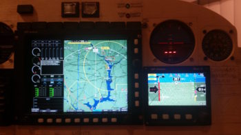
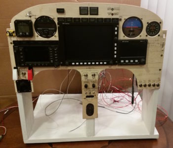
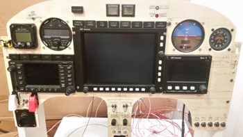
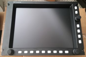
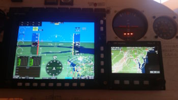
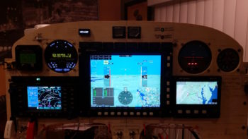
Here’s another shot with some slightly different screen views than above.
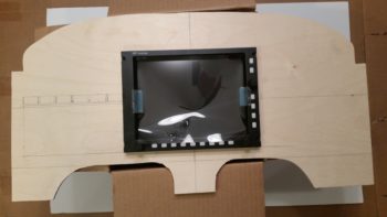
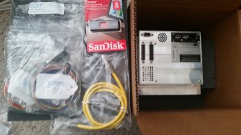
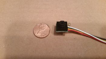
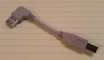
Upon checking my mail I found that I had received the 4″ USB dongle I ordered to connect the HXr EFIS display to the 4-port USB hub. The USB hub connects items such as the Radenna SkyRadar ADS-B IN Receiver and by adding a little nub of a USB device also provides Bluetooth capability for the GRT EFIS system. Specifically, with a small Android tablet the GIB will be able to see essentially the same info on the PFD as I do up front.
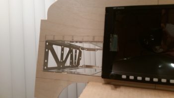
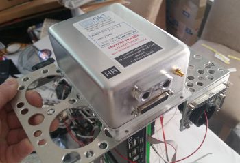
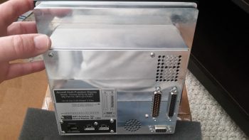
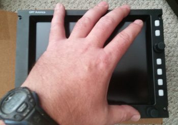
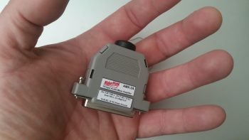
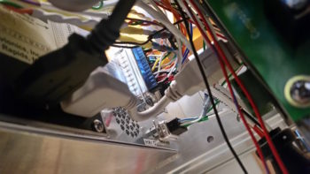
I then installed the USB dongle . . . this is the HXr EFIS side
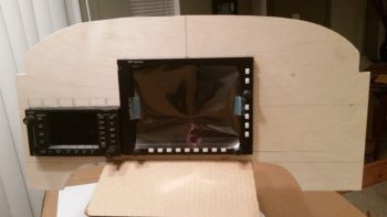
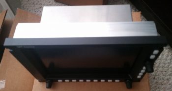
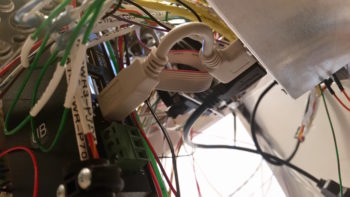
And here is the 4-port USB hub side. You can see there is not a lot space behind (again, technically “in front of”) the EFIS display unit.
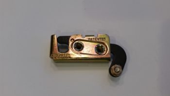
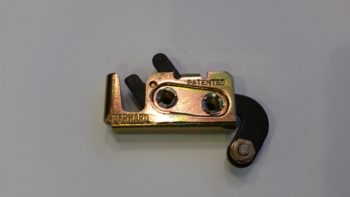
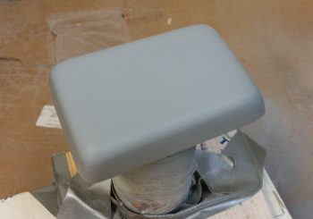
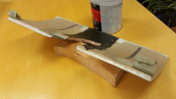
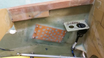
I also received the parts from ACS that I was remiss in ordering in a timely fashion. With the #2 CAMLOC receptacle in hand I then pressed forward with the pilot thigh support cover CAMLOC locking tabs installation. Two items worthy of note on these CAMLOC tabs is that, first, I realized I did not have countersunk rivets large enough to mount the CAMLOC receptacles to the tabs…. hmmm? I quickly determined that a #6 countersunk screw would do the trick so I rounded up some of those (I only had the fancy SS hex drive #6 screws that would work) and some locknuts and got to work.
The second issue was that the left tab would not sit flush with the lower instrument panel cross piece and that it really required some force to get the thigh support cover to seat down in its proper position. Of course I didn’t notice this until the receptacles were mounted in place and the CAMLOCs were installed tightly. I fiddled around with it for a bit and realized it just wouldn’t work with the bracket at a 90° angle since it was obvious the angle must be more acute. I don’t really like bending composite components with heat because things can go south quickly, but I bit the bullet and did just that. I used a scrap piece of wood to mount the bracket to and then judiciously applied heat and was able to bend the bracket into a more acute angle and . . . Voila! . . . worked like a champ!
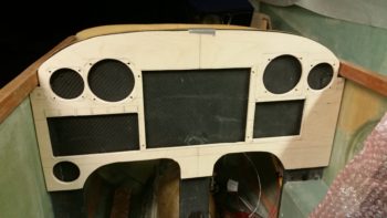
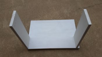
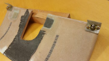
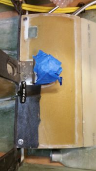
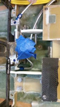
Here’s another shot with the thigh support CAMLOC brackets ready to be floxed into place into the fuselage at the base of the instrument panel bulkhead.
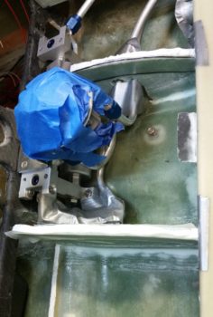
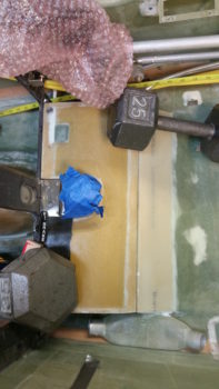
Ahhh, this familiar site! What could it be?? Well, this time around of course it’s the thigh support CAMLOC brackets floxed into place and curing.
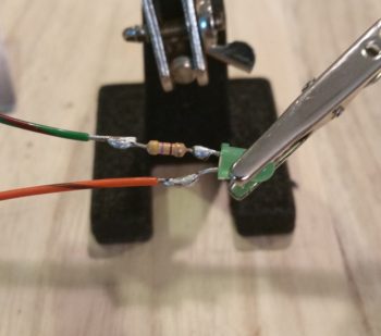
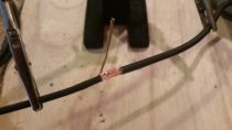
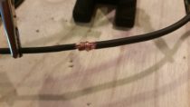
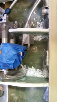
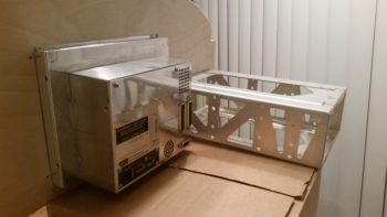
While the thigh support CAMLOC brackets cured, I prepped the Trio autopilot pitch servo for removal. I needed to remove it for a twofold purpose: 1) I needed to repair 2 of its P3 connector pins that were NOT toning out, and 2) I needed to hook it up to the panel-mounted Trio autopilot control head for testing.
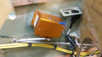
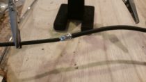
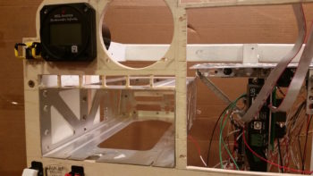
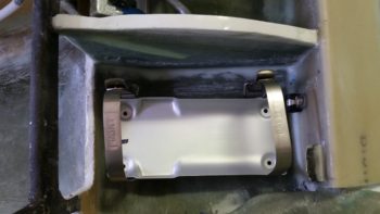
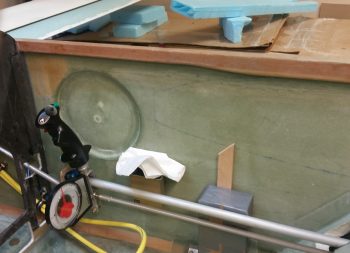
I forgot about the cool looking base floxed into place inside the right side of the nose, so I figured I would grab a currently rare shot of no pitch servo mounted on the side wall.
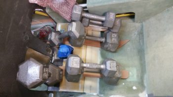
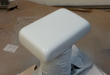
A bit later, after I confirmed the flox had cured, I pulled the weights off of the pilot thigh support cover and checked the fit of the now CAMLOC-secured cover. Bottom line, as my buddy Dave B. from OZ would say, “It works a treat!”
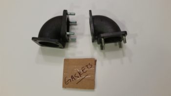
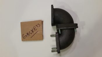
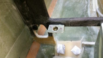
Here are the left and right CAMLOC receptacle brackets now permanently floxed in place at the base of the instrument panel.
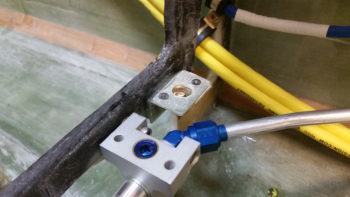
And here’s a shot of both thigh support CAMLOC receptacle brackets.
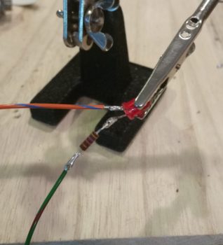
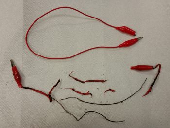
As I finished wiring up the Trio Pro Pilot autopilot into the instrument panel mockup, I first repaired the 2 errant connector pins on the pitch servo and then connected both servos to the Trio autopilot control head.
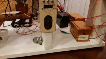
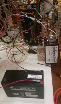
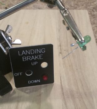
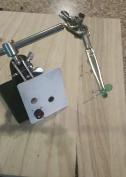
I also ginned up a quick little mount for a temporary autopilot disconnect switch just in front of the intercom. I picked this spot since my actual autopilot disconnect switch is on the control stick.
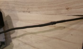
BTW, the connector you see in the Adel clamp attached to the outside upright of the instrument panel mockup base is the P5 connector, which attaches to the control stick cable connector.
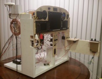
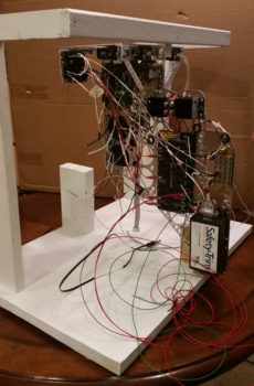
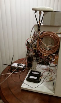
Although I temp-mounted the GNS480 GPS antenna puck last night, I thought I’d get a shot of that and the newly connected Radenna SkyRadar-DX ADS-B IN receiver sitting down low in front of the instrument panel mockup base. You can see that I zip-tied its own GPS antenna puck to the top of it, this making GPS antenna puck number 5 that is currently connected to this panel mockup! If you’re curios, here’s the list:
1—GNS480 GPS Receiver
2—HXr AHRS
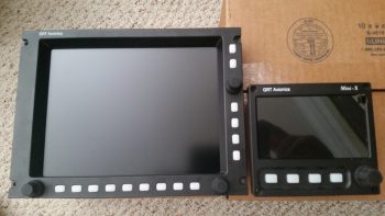
3—Mini-X EFIS
4—TruTrak ADI
5—Radenna SkyRadar-DX ADS-B Receiver
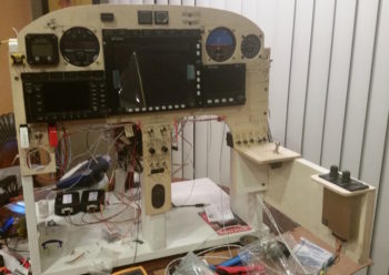
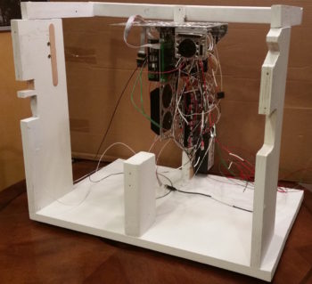
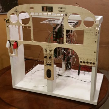
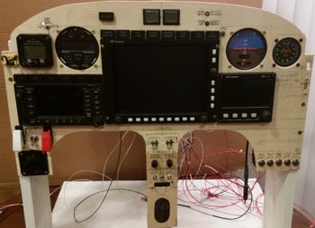
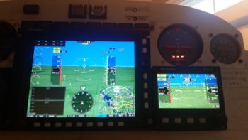
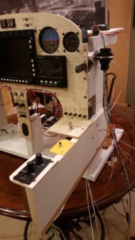
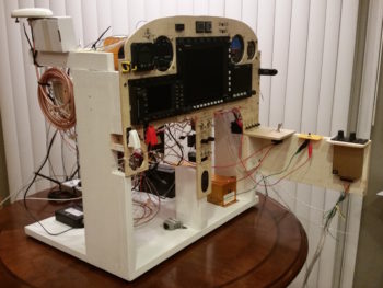
Ok, so here’s the latest shot of the mocked up instrument panel, ready for official power-on test #2 . . . which means that I am really just checking out my Trio autopilot wiring installation.
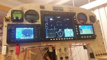
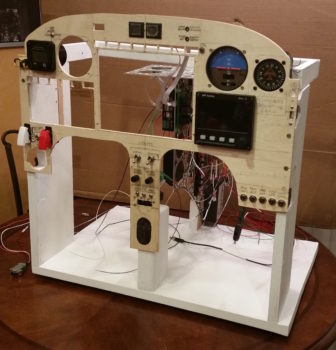
And here’s the panel with power fired up again. A quick note that not only did I resolve my AHRS connection issue, but I was able to tweak my GNS480 external annunciator lights and rewire the OAT probe on the MGL clock, so all of my 3 issues from yesterday are resolved.
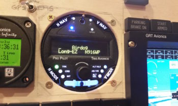
My last act of the evening, as I was doing some minor configuration inputs on the Trio autopilot, was to personalize that sucker to make it MINE! [Note the blue GPSS LED light lit up as the Trio AP is talking to the GNS480 GPS receiver…]
Alrighty then my friends, tomorrow I plan to work on both the thigh support cover piece that will wrap around the fuel selector valve to finish off the thigh support install, and also work on finalizing the Dynon intercom wiring connections as much as possible.