Chapter 13/22/25 – Pitch trim actuator install

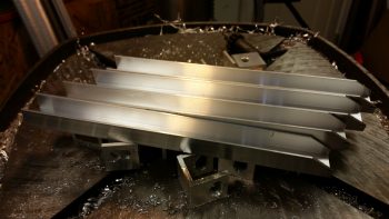
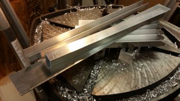
I actually took the first 2 pics yesterday, but since I was heading out to meet some friends, and was trying to field an influx of phone calls, I missed my window to mount the pitch trim hardpoint into the sidewall.

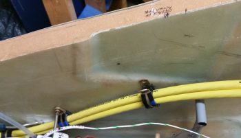
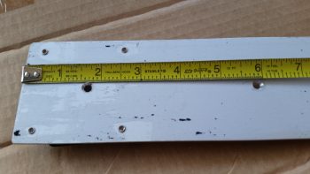
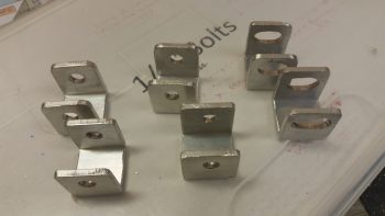
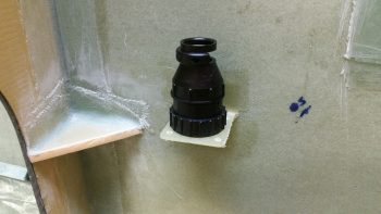
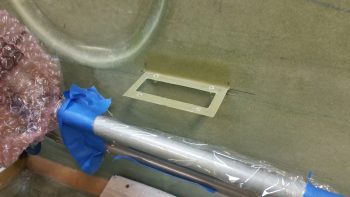
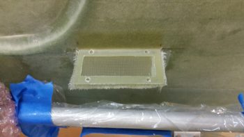
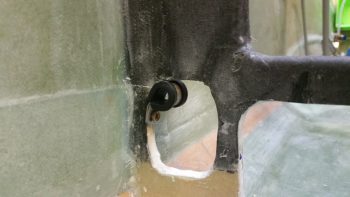
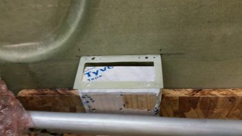
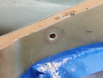
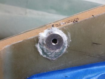
No worries since it just gave me more time to figure out my exact plan on how to embed the pitch trim hardpoint into the right sidewall.  Below you can see that I started drilling out the hole where the hardpoint will get floxed/micro’d/flocro’d into place.

Today I finished the pitch trim actuator assembly hardpoint install, although when I got home my phone was dead, and it being my current camera I didn’t get a few key intermediate pics… and I really needed to proceed with this install since I’m falling behind schedule on this build!

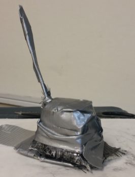
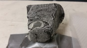
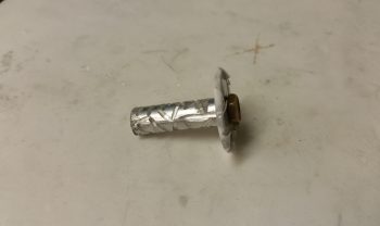
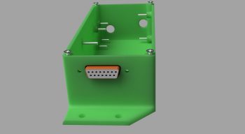
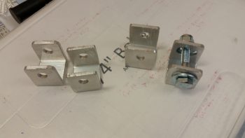
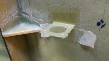
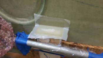
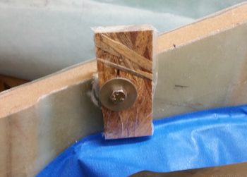
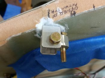
I took a scrap piece of wood, drilled a 1/4″ hole into it, then covered the outboard side with packing tape.  Not shown is the clamp and the wedge that I used to keep the head of the bolt fairly parallel with the aircraft CL, and the face of the mounting hardpoint near 90° vertical.  This pic was taken a little while after I had removed the clamp and the wedge, when clearly my phone was recharged.

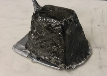
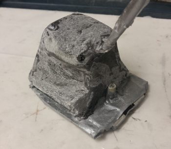
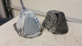
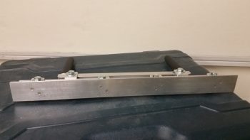
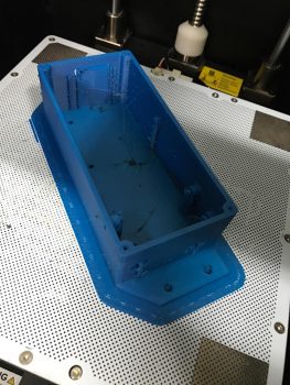
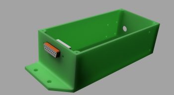
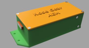
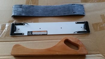
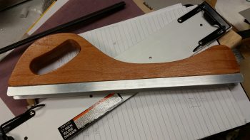
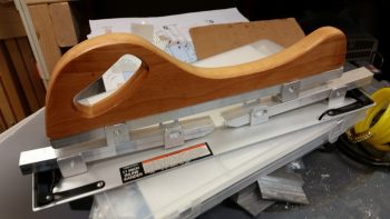
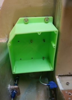
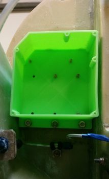
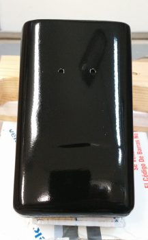
While I let the pitch trim mounting hardpoint cure, I wet sanded the tool box with 500 grit wet/dry sandpaper, let it dry, then mounted it, and hit it with 2 good coats of clear coat.

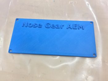
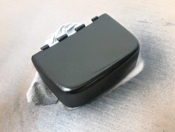
While the lower tool box body clear coat was drying, I then wet sanded the tool box lid, which of course proved to be a bit more stubborn than the tool box body in smoothing out the surface imperfections.  I got to a point where I just needed a bit of clean up around the corners when of course –although being VERY careful– I broke through the black paint to the primer below.  This tool box lid truly is proving to be the problem child from hell!  So, I dried it off and hit the corner edges with 2 more coats of black paint.  I’ll let it dry a few days before wet sanding it again and hopefully getting a few good coats of clear on it!

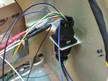
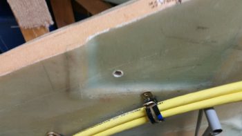
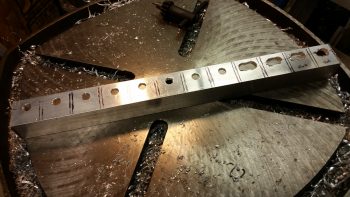
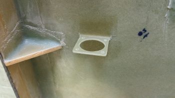
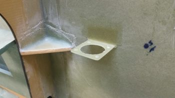
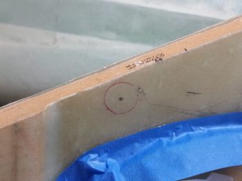
Here’s another something that I didn’t get a pic of earlier.  Apparently, when I drew my install point target circle, the geometry of how the mounting hardpoint fit into the sidewall was different when I could actually test fit the hardpoint piece IN the sidewall.  The original hole started in the lower left corner in relation to where I eventually mounted the hardpoint, which of course meant backfilling the open area of the hole with spare Divinycell foam.

I also knew that even though I drove the position of the mounting hardpoint as far forward and up as I could, that I still may very well need to rewicker the mounting bracket to get the spacing and/or alignment of the pitch trim assembly correct.  In addition, I know this hard point install won’t win any beauty contests, but just keep in mind that this will all get sanded, floxed, and covered with 2-3 plies of BID when the nose top gets constructed.

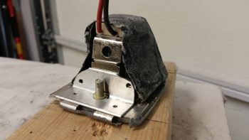
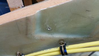
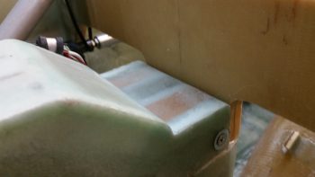
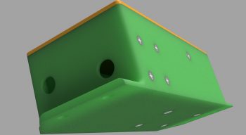
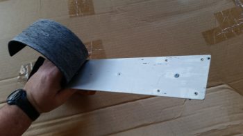
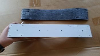
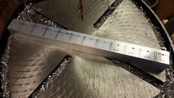
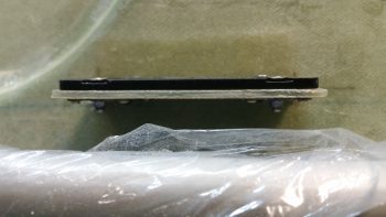
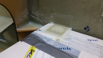
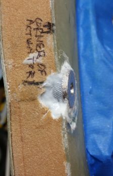
Here’s a downward shot of the pitch trim mounting hardpoint showing the mounting face of it straight in comparison to the sidewall.  Also, although hard to tell in the pic, the face is also vertical where the sidewall tapers out slightly as its height increases.

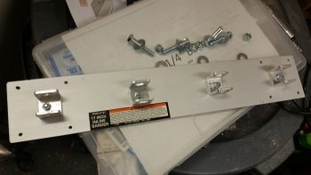
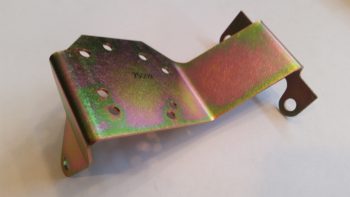
With the micro & flox pretty much cured, I then attached the mounting bracket to test fit this sucker!

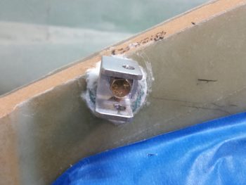
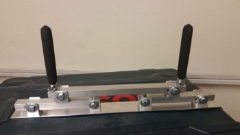
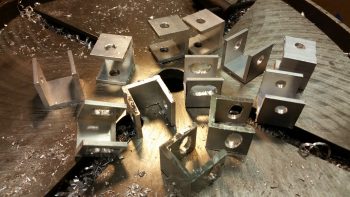
I took about 10 minutes to file down both the top & bottom edge of the swivel bracket to allow for a better fit inside the U-channel mounting bracket.  Below you can see it swiveled inboard.

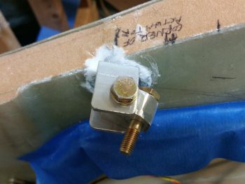
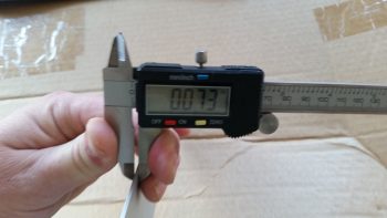
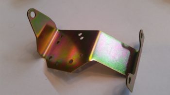
And here it’s swiveled outboard.  If it doesn’t look like it’s swiveled outboard much, you’d be right!  I still need to shave down the width of the swivel bracket on the outboard side by about 0.10″ so that it has clearance to swivel outboard the required amount.

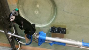
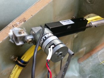
I then mounted the pitch trim actuator and assembly.  I could instantly tell that this entire assembly was sitting about an inch low.  My suspicion when mounting the hardpoint proved correct, meaning I’ll have to rework the mounting bracket assembly.  I’m still very happy with this install though since I’ve refined my target positioning from about 50 meters down to 5 meters . . . meaning that while not in it’s final, spot-on position, it’s very close and very workable!

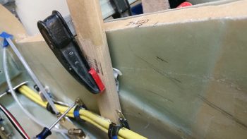
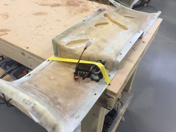
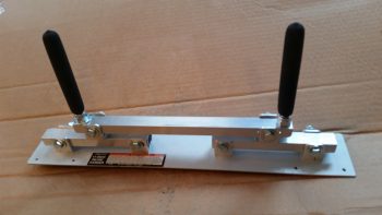
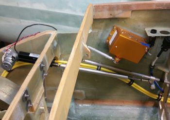
Here’s a wide angle shot of the entire pitch trim assemble.  In his install directions, Vance Atkinson states to mount the pitch trim assembly at a point on the elevator control tube about 1.5″ forward of where the control tube passes through the instrument panel.  Right now, I’m about 3/8″ (0.375″) forward of that (so, 1-7/8″ forward of the panel).  I’m hoping since Vance had his assembly pretty much parallel with the aircraft waterline, and mine is much more aligned with the actual angle of the elevator control tube, that the added 3/8″ won’t be an issue.

[Note: As I understand it, some Strong pitch trim units installed in the same position where I’m mounting mine proved to be a little problematic, with resulting minor oscillations and difficulty in trimming the aircraft.  Of course I’m not using a Strong unit, but nonetheless I’ll keep my eye on these potential issues and work to correct them if need be.]

Ok, although not a slam dunk right out of the gate, I am –again– very happy with how the pitch trim unit install is going.  I like it up front here because although it’s tight quarters where I’m installing it, it moves weight forward, keeps the aft part of the airplane more clear of components, results in much shorter power wires, and should keep my comms clearer & more noise free due to the motor works being away from any of my comm circuits.


Chapter 22 – A lighter EZ day . . .

First off, I want to apologize for the first two pics being out of focus.  It’s hard to tell sometimes how they look on the phone screen until later on.  I think there’s plenty enough detail to get the idea of what I’m on about with these pics though.

I started off today wiring up the remaining cavities in the P5 connector, which routes all the wires for the pilot Infinity control stick grip.  The proof is in the pudding when completing these bigger wiring tasks, as so too it is when you finally get down to wiring up these connectors to the end components.  I spent a fair amount of time working over the pinout diagrams beforehand to make sure they were as spot-on as possible, but when the wiring starts –like any best laid plans– things change. Wiring sizes, wiring colors, wire size or color availability on-hand, routing, etc.

In addition, since my new nose gear system is operational, I’ve been scavenging the longer, terminated wires off of the old nose gear wiring harness to use in both the P5 (and P4) connectors.  This changes the wire colors sometimes since re-utilizing good terminated wires that may have a different random color than the first random color I chose is more important to me than sticking to an arbitrary random color!  To be fair, some colors (power & ground) are a bit more sacrosanct to me, but the other random stuff I swap out in a heartbeat.

As you can imagine, there are a lot of rabbit holes to chase down to get all the wiring accounted for in these harnesses.  With the P5 (control stick) and P4 (throttle) connectors being two behemoths in this wiring system, they really do interface with a lot of system end components. For example, although not a jaw-dropping number, if you look at the wires (there’s 3) in the lower left corner of the pic below of the associated Trio Pro Pilot Autopilot wiring harness, one goes to the P4 connector and the other two are terminated together into the P5 connector.  To terminate these wires, a general idea of the routing and a quick mockup is in order to figure out the length. Obviously the length doesn’t have to be perfect, but longer is always better (EZ’er) than shorter.

After figuring out, verifying, and finalizing all the wiring connections, terminations & routing on the P5 connector, I then set my sights on the P4 connector.  It too deals with a myriad of electrical system end components in and around the panel, including Triparagon-mounted items, GNS480 GPS, and even the Landing Brake (see below).  It took me a bit of time to verify the connections on these wires as well, but I confirmed all that was good, and tweaked a few things that had been superseded yet not annotated (by me!).

All in all it was a good day, and I’m really glad to have knocked these two connectors off of the list of prerequisite items that need to get completed before I start on the nose top.  To be certain, in each connector there are a few wires that I actually didn’t mount into the actual connector cavities.  However, I did cut all those wires to length and terminated them, so they are ready to go.  This might help explain why you don’t see the wires wrapped with flightline tape nor any of the cable clamps mounted.

One thing that finalizing the P4 connector wiring above allowed me to do with minimal extra effort was to test out the operations of the Landing Brake using the throttle-mounted landing brake switch.  I haven’t actually run the landing brake in (I think) going on almost 5 years now!  So, to knock some of that rust off . . .  here goes:

I do have about a half dozen connectors to terminate on the end unit side (mostly on the roll trim relay board), which I plan on getting to later tonight or earlier tomorrow.  I’ll also be mounting some Adel clamps and wire-securing hardpoints in the avionics bay (area between the panel and F22) tomorrow as well.


Chapter 22 – Taxi light cover salvaging

Today was the Big Reveal day for the taxi light cover.  Since my layup was practicing the truest form of accelerated entropy last night, I simply covered it with Saran wrap and taped it up profusely!  This morning I took off the long cross pieces of tape that I used to keep the whole layup from squeezing up the sides of the taped form, really making the cover unusable if it had.  I was now at the precipice of finding out what I had underneath of all this tape.  Would it be usable?  Would have I have to start all over again from square zero?Let’s find out . . .

Ok, so here’s the result in Airdog’s crazy layup experiment emporium.  Quite an interesting specimen I’d say, but it really does look usable.  As I’ve mentioned many times before, so much of these one-off custom jobs are ITERATIVE processes!

I grabbed my sanding block and my Perm-A-Grit tools and went to town on the taxi light cover.  I knew that I would most likely create some holes in this cover to get the shape worked out correctly . . . and I was right.  It is interesting that the resulting pics all look quite a bit like snake skin.

Here’s the opposite side.  It may be a bit difficult to see, but because I taped the top of the cover down, it resulted in 2 actions:  One negative, and one ok.  The negative action was that it created “shoulders” on each side of the cover just below the top.  My plan was to cut these off and layup a ply of BID that will bridge across the resulting hole.  The squashing of the top resulted in the 2nd action, which was that it pushed the sides just below the “shoulders” inboard more…. which was fine and actually allowed for a tighter fitting cover (i.e. takes up less room).

Here’s the sanded taxi light cover next to the taped up taxi light that I used as the cover form.

Also, here’s a shot of the inside of the taxi light cover.  Aside from scratches from the scribe I used to pry the cover off, the carbon fiber really looks nice.  Overall, this pic again has a snakeskin look to it (Marco also pointed this out when he saw it).

After assessing the cover’s usability –including cover mounting & removal– I decided that because the lips on each side clamp around the flanged base of the taxi light bulb mounting assembly, that I it was not practical to keep the forward side of the cover in place.  I cut off the forward face of the cover to simply allow the cover to be slid on from the bottom (if it’s deployed/out) or aft (retracted) side of the taxi light.  After testing this configuration I could tell immediately that I had made the right call on removing the forward cover side.  Much easier!

I then prepped it for more glass (repair layup, if you will . . .) by sanding it to shape.  This prep also included using the Fein Saw to remove the right “shoulder” just below the cover top, which left a decent-sized hole in the cover.

To keep this story line flowing, I’m jumping ahead here with my pics.  The pic below is exactly what I did above, but on the cover’s left side.  The yellow epoxy spreader is being employed as a form weight to keep the overhanging glass flat against the side lip.  Besides wrapping around the taxi light bulb mounting base to keep the cover securely in place, this side lip will get drilled in 2 places, and be held in place with two 4-40 screws.

In addition to the taxi light cover, I continued to work on securing the 2 big power cables (one + power and the other – ground) that start in the nose battery compartment and end at the firewall & starter, respectively.  Again, I had to reroute these cables up and over my rudder pedal (you can see in the pic how they get in the way if not wrangled) in an arch/ Bell curve fashion.  With the 1st added Adel clamp in place, I marked the position for the 2nd additional Adel clamp.  Note in the upper right hand corner of the pic my markings for the Atkinson pitch trim actuator mounting.  You can see that I need to get these power cables as high up on the nose sidewall as possible, but still remain clear of the pitch trim actuator mounting.

After marking the spot, I then drilled the hole in the nose sidewall.  This area was a bit tougher to drill since, if you recall, that indented area that this hole was placed has additional plies of BID to beef it up for the mounting of the pitch trim actuator.

I then performed the “poor man’s” knurling of the 10-32 threaded aluminum insert that will be used to mount the Adel clamp in this location.  I wanted to use this threaded insert since it’s a bit more robust than a RivNut.

I then whipped up some flox and mounted the threaded insert assembly (including a taped washer mounted to it with an AN3 bolt).  I then clamped it in place to ensure it would be level with the surrounding sidewall surface when it cured.

Here’s a shot about 10 hours later after it cured to about 80-90%.  The flox was still just barely soft enough to be easily removed with a razor blade (there was an entire ring of it around the perimeter of the taped washer).

Although it’s a bit slow going, I am getting through all the electrical related taskers on my list.  I expect about another week, maybe 2 at the most, before I’m ready to get back to the big chapter build items again.


Chapter 22 & 25 – Done, Done & Done!

Today I got a few things checked off the list.

First, I finished constructing a micro spreader to hopefully accelerate the finishing of the aircraft surface in prep for painting when the time comes.

Here’s a shot of the actual bottom plate working surface.  You can see I used 2 counter sunk aluminum rivets per bracket to hold the bottom spreader plate to the 4 individual brackets.  I figured 2 rivets per bracket would be enough since the primary force on the spreader plate is from the top as it pushes the micro over the aircraft skin.  If there is any issue I can of course beef up the bracket attach points.

Next, I got this pic from Marco showing my finished Nose Gear AEM box and a United Airlines bear he picked up for my little 7 year old buddy (a friend’s daughter) who loves flying.

Finally, the box Marco 3D printed for me for the Nose Gear RCU had a slight blemish on the lid, so I’ll hope he’ll forgive me for me filling it in a bit and painting the lid black.  Here’s the finished Nose Gear RCU box ready for mounting into the aircraft.  I will of course have to terminate the wires on the “B” side of the connector.

With my bridge sander, micro spreader and RCU box distraction projects out of the way, I can now get back to my list of electrical system related taskers that need to get knocked out.


Chapter 22 – 3D Printing AEM Box

Not me of course!  I just got these updates from Marco.  After some trials and tribulations with his 3D printer he was finally able to get a good print on both the AEM box . . .

… and the AEM box lid.

Since I pulled the trigger on the Laserware SF11/C laser altimeter I will soon have all the components required to implement Marc Zeitlin’s new nose gear Auto Extend System, with a twist of course: the backup battery emergency gear extension feature.

To get an idea of what it will look like installed, this is Marc Z’s laser altimeter installed on the inside of his Cozy gear leg cover.  Of course the Long-EZ doesn’t have this gear leg cover, so my laser altimeter will get installed inside the hell hole near the gear.  Also, note in the pic below that Marc mounted the 12V-5V converter near the laser altimeter, whereas my converter will be located in the AEM box above.

Finally, in a discussion I had with Marco I send him this pic of my GRT Mini-X Magnetometer.  Since I had it on hand I thought I would post it here.

It’s been a bit of effort to get Marc Z’s new gear system implemented, especially with redesigning the 1.2A backup battery emergency extend circuit back into Marc’s scheme. But in the end I think all this extra effort will definitely result in a much more refined, simple, optimized and user-friendly nose gear system.


Chapter 22 – Nose Gear AEM Box

Here’s the latest status on the Nose Gear Auto Extension Module (AEM) that will replace Jack Wilhelmson’s original AEX feature.  First off, I sent this pic to Marco to help show him why I had a requirement that the AEM box be 1.8″ or less: since the AEM box will be mounted in the old AEX box spot, where I have a notch in the top aft side of my NG30 cover that is just a hair wider/deeper than 1.8″.

After a number of discussions back & forth with Marco on the particular specs of the AEM box he was able to generate these fantastic renderings of the box.

Here’s the initial rendering.

Then one with the lid and raised letter labeling.

One of the aft, left and top side.

Finally, one showing the internal standoffs for the two airspeed switches and mounting screws.  As you can see, he has included the 15-pin D-Sub connector in the renderings as well.

In the next few days Marco will 3D print this AEM box when he gets a chance.  I just really have to say that everything for the new nose gear wiring & AEX system is going exceedingly well!


Chapter 25 – Self-rolled Bridge Sander

I took a bit of break from my normal build actions to do a quick tool building project. Starting yesterday & finishing today I’ve been working on constructing a bridge sander as Nick Ugolini spells out how to do on his blog.  Once again, I was notified of this brilliant contraption by the watchdog of the canard world, my friend Dave Berenholtz who is blazing through his Long-EZ build down in OZ (check out his blog here).  Coincidentally, Mike Beasley also built one of these as he was finishing up the major sanding of his Long-EZ as well.

For the base, Nick calls for using 1/16″ thick x 1-1/2″ wide aluminum that you can easily buy from Lowe’s, Home Depot, etc.  I did pick up some of that aluminum for the micro spreader, but for the sander it just wasn’t wide enough for me so I picked up a cheap automotive rigid sander at Harbor Freight after assessing that the aluminum base looked as if it would be amenable to getting pressed into service as a flexible sanding board.  As for parts, one other point of note: Nick calls out for 1″ square tubing to be turned into 6 U-channel pieces and then a separate piece of 7/8″ U-channel to be used inside the 1″ share tubing/U-channel above.  Well, I found the 1″ square tubing, but not the 7/8″ U-channel so I ended up using some 1″ wide U-channel I had on hand with 1/8″ walls, then buying 3/4″ U-channel to go inside that.  Just a slight variation that worked out really well.

I started off by ensuring that I could dismantle the Harbor Freight sander to ensure I wouldn’t destroy it in the process.  I peeled the rubber pad off the bottom of the base to gain access to its 4 handle mounting screws.

I simply used my fingers to pry off the bottom rubber pad, with an occasionally use of my utility knife to round up any errant pieces of rubber that decided to stay on the aluminum rather than come with the rubber pad.

With the sander broken down into an acceptable number of pieces, I then did a final assessment on whether the aluminum base would be flexible enough to be used in this type of sander.

Since the base off the HF sander is only 0.01″ thicker than the 0.063″ (1/16″) called out for by Nick, it looked as if my eevil plan was going to work!

An added bonus in using the HF sander was that the screw holes in the base for holding on the wood handle are at the perfect dimensions that Nick calls for on his blog: approx. 1-1/2″ and 6″, respectively, from each end.  Pretty cool.

I cut enough of the brackets and aluminum pieces for two of these things since I’ll also be building the micro spreader, but I wanted to get the sander under my belt first.  I marked up the U-channel for 12 each 0.9″ wide brackets, 6 for the sander and 6 for the micro spreader.  Of the 6 brackets for each, 4 will get normal holes drilled through them while 2 will require slots.  Since I’m using cheaper Zinc bolts, 1/4″ is the smallest diameter I could get (versus the 3/16″ AN3 hardware Nick used).

For easier drilling of the holes and the slots, I drilled them all before I cut the U-channel into the respective brackets.  Yes, since I don’t have a mill my slots are pretty sloppy, but for this purpose I’m sure they’ll work fine.

I then cut 12 brackets from the U-channel

And then cut the 3/4″ U-channel into the approximate lengths for the first layer of cross supports.

Finally, I cut the 1/16″ x 1-1/2″ aluminum for the micro spreader to 16-1/2″ long.  I also cut 2 longer lengths of the 3/4″ U-channel stock for the top cross supports/handle bases.

I drilled the 4 holes through the U-channel for my bridge sander and mounted the handle base.

And then started the arduous process of cleaning up each bracket.

I cleaned up 4 straight-holed brackets and 2 slot brackets for the bridge sander, and left the 6 brackets for the micro spreader for later.

I then mocked it all up to see how it would look.  Not bad!

I then drilled a hole in each of the bottom brackets that attach to the base for mounting.  I drilled them just a bit off-center to allow for mounting one countersunk rivet through the base into each bracket to keep the alignment straight.  This was the last action of the evening since I wanted to ponder on the handle a bit.

I called it a night, but I couldn’t help but get the feeling that I needed to go with the “traditional” 2-handled setup vs. using the HF sander’s wooden handle.   So this morning I used the handle base/cross support 3/4″ U-channel stock that I had cut for the micro spreader and drilled the final holes into it to allow it to be bolted to the two sander cross supports, and also add two 3/8″ bolts for handles.  I cut about an inch off the top of each handle bolt to allow me to use rubber slip-on grips from McMaster-Carr.

It looked good, but my quick testing of it proved to me that it’s the downward force against the surface being sanded that determines the conformal action of the sanding base, not the actual configuration of the handles.  So my initial hunch was right, and thus I’ll drill up the the base with the wooden handle to see how that works.

I have out-of-town company so the build will be a bit slow over the next few days, but I am happy that I got this reportedly invaluable finishing tool constructed.


Chapter 22 – Final Brackets, this time!

After the BID glass cured on the Throttle Handle electronics cable P4 connector bracket, I pulled the peel ply and razor trimmed the glass.  As I was redrilling the connector mounting holes I set this connector body in place to ensure the spacing was good.

So, here’s the final product for Throttle Handle electronics cable P4 connector bracket.

I then did pretty much the same thing for the Dynon Intercom bracket: pulled peel plied, razor trimmed, redrilled holes and sanded it all to clean it up.  I then set the intercom in place to see how it fit.  I’m definitely happy with how this intercom mounting is turning out so far.

What I’m not happy with is the forward right bracket nutplate.  It’s giving me fits and I’m going to have to drill it out and remount just a hair forward and inboard for it to align correctly with the intercom mounting hole.

Of course the other 3 nutplates went in without any issues, unlike the last one!

Besides redoing the 4th nutplate, I’ll also assess whether or not I need an angled strut at one or either end of the bracket to help support the cantilevered intercom.  I must say that this bracket is amazingly strong, but with vibrations abounding in flight I think I’ll throw on one small corner bracket to bolster it a bit.  It will weigh next to nothing but will add a lot of structural support.


Chapter 22 – More Brackets & RCU

I started off today by razor trimming the bracket for the Throttle handle electrical cable P4 AMP CPC connector.

I did the same thing for the right armrest-mounted Dynon intercom bracket that I just glassed in using 2 plies of BID.  On both of these brackets I was able to knife trim them right at their curing sweet spot, so the glass was definitely more on the cured side, but still just a tad pliable . . .  so it cut well.

I then laid up 2 plies of BID on the bottom side of the Throttle handle electrical cable connector bracket.  I used a small flox fillet in the corner and peel plied the glass junction with the sidewall.

I did pretty much exactly the same thing on the Dynon intercom bracket only for a bit more strength I used 3 plies of glass on the bottom side.

Speaking of brackets, I just received this today so I thought I’d throw it on the blog.  This is the fuel injection spider mounting tab that goes on the top centerline of the engine.  Yet just another item that will go on the shelf for the time being.

With my bracket glass curing, I started in on mounting the 4 beefy relays into the gear Relay Control Unit (RCU) box . . . fitting name, eh?!  The first relay to go in was the clear cased 3 pole Auto Extension (AE) relay, RL000.  It handles the actual engagement of the gear Auto Extension feature and also is a pass-thru for all the major electrons running the gear up or down.

I ordered this relay specifically with bottom mounting tabs, with the corner of the left tab needed trimmed diagonally just a hair for it to fit properly.   It mounts with a 4-40 screw on each side, each coming in externally from the back.  All the mounting screws coming in from the back side are countersunk to allow the back surface of the box to remain flat, which facilitates ease of mounting the box to the aft side of the Napster bulkhead.

Next relay up to get mounted inside the box was RL003, or the AX relay.  This relay is the one I added back into the mix that charges the small 1.2A backup battery that was provided in Jack Wilhelmson’s original design.  Relay #3 takes control of the system in case of a power emergency to drop the gear down using the 1.2A backup battery for power.  In Marc Zeitlin’s new gear wiring design he doesn’t use this relay since his system incorporates a manual (ratchet) drive for emergency gear extension.

Finally, as for relay #3, I mounted this guy first since it has a unique feature that needed to be dealt with that the other two black relays don’t: down along the top side of the relay is the RXEF-250 wafer style fuse soldered into place that’s used during backup battery charging.  Getting under this fuse to install the K1000-6 nutplate would have been a lot more difficult if I couldn’t get in from the side (where the other two relays sit) to mount the nutplate.  After I mounted this relay, I put some double sided foam sticky tape underneath the wafer style fuse to keep it mounted to the front of the relay for anti-vibration.  I also tipped the box right side up and glopped some E6000 adhesive (yep, the stinky stuff) onto each edge of the fuse to keep it secure to the relay, banned the box outside on the deck for a few hours while it cured and I took off to run some errands.

Upon returning from my errands (which included buying parts for the flexible sander Nick Ugolini describes how to build on his blog) I installed the last two relays: RL001 & RL002 [Note: Simply for space I truncated the relay IDs and labeled them on the actual relays with RL0, RL1 … etc.).  As you can see, these two relays simply control gear up and gear down, respectively.  All went well except for the life of me I couldn’t find a 6th K1000-6 nutplate to use on the top side flange of RL002.  After searching for a good while, and simply not finding the pack of 23 I show having on hand (simply maddening!), in order to get this thing wired up tonight I improvised, adapted and overcame by using an aluminum binder stud, cutting off the top and then quickly Dremeling a not-so-pretty slot for a bladed screwdriver.  I doused it with a good measure of blue Loctite and in it went… Voila!

Here’s another shot of my mounting improvisation . . .

Over the next couple of hours I confirmed & verified the wiring in this box matched exactly what was on the diagram.  Having had to pull all the terminals off their posts, I used a pair of channel lock pliers to compress the terminals just a bit to ensure their clamping pressure was nice and tight.  I then slowly replaced all the terminated wiring back onto the relay posts, performing a continuity check as each set of wires went back in.  After all the wires were back in place, I zip-tied them into place to ensure no wires would be vibrating and wreaking some future electrical havoc by gnawing through a neighboring wire, etc.

Here’s just a closer shot of the internal RCU box wiring . . .

I then cut & terminated all the wires with AMP CPC sockets.  Again, as I finished each wire I performed a continuity check to ensure all was electrical good on that wire circuit from source to connector.

With all the RCU box wiring set to be terminated into the AMP CPC connector, I called it a night.  I may have actually done a bit more but it was quite late and I was collaborating online with Marco (who was in Hawaii for work!) on the specs for the AEM box.


Chapter 22 – RCU Box & Brackets

I didn’t get the intermediate steps documented since I’ve been out & about this weekend with friends.  Here is the final result of the Clickbond mounting for the Nose Gear RCU box.  Again, I used 3 plies of BID along the top row (2 Clickbonds) . . .

. . . and 3 plies of BID along the bottom row (3 Clickbonds).  After curing, I pulled the peel ply and cleaned up the goobers.  Thus, the RCU box is officially mounted.

A little sideline tasker I completed was to drill and flox in place this Adel clamp for the Throttle electronics cable that terminates into the P4 Connector.

After pre-drilling the 4 screw holes and the 8 holes for the K1000-6 nutplates, I then did a final trim & sanding on the Dynon Intercom bracket.  I determined where its position needed to be and marked the sidewall.  I then 5-min glued the intercom bracket to the sidewall.

I then laid up 2 plies of BID (pre-pregged of course!) on the top side of the intercom bracket, and peel plied it.

I pretty much followed the same steps for the Throttle handle electronics cable P4 connector bracket just forward of the instrument panel on the left side.  After 5-min glueing it to the wall, I laid up 2-plies of BID and peel plied it.

These tasks above are all on a list of 10 electrically-related items that I want to have finished before I move on to the wheel pants.  Once these brackets and the RCU box wiring are completed, I’ll be down to about a half-dozen items on the list.