Chapter 22 – Armchair Pilot?

….GUILTY!

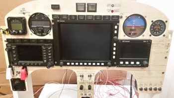
Since my last update I’ve been continuing down the path of finalizing my EFIS checklists, to include my education on how the GRT HXr, Mini-X, Trio autopilot and GNS480 GPS all play together during normal sorties, and specifically during instrument approaches.

Since the “online” checklists on the GRT HXr are simple small-sized text files, it means that A) they take up very little thumb drive space, and B) I can add virtually as many as I want. Since the integration of my glass cockpit comes with a decently high learning curve, this led me to make crib notes for the pertinent functions, especially the ones that had either befuddled or eluded me for various reasons (typically ignorance, ha). I’m seriously under no illusions, knowing that after another 6 months of in-depth building I’ll have forgotten the majority of what I just learned… thus, hopefully my crib notes will facilitate glass cockpit mental reintegration much more quickly!

Besides continuing to add to my checklist library, it also got me back into the manuals and other various reference material specifically focusing on GRT EFIS-based instrument approaches. Case in point, a gold mine I found on the GRT forum from a response that Bob Turner (resident forum non-GRT-employee EFIS guru) provided a GRT newbie was a 3-page how-to for setting up the autopilot, managing climbs & descents, shooting precision & non-precision instrument approaches, and missed approaches.  The only catch was that Bob’s notes were specifically geared towards an HX EFIS, which is close to the HXr, but requires a bit more button pushing.

In addition, my first real scheduled 28-day cycle navigation data update from Seattle Avionics was due, so while I fiddled about with figuring out the idiosyncrasies –and there’s a distinct few– of that process [I tried to do it overnight as Seattle Avionics recommended, but that didn’t work…. but I think I can get it to next time] I went to work concurrently testing out Bob’s 3-page knob-twisting and button-punching EFIS how-to on instrument approaches.  I finally got the multi-hour Seattle Avionics nav data download completed [this data covers approach plates, airport diagrams, sectionals and IFR low charts] and was still into documenting pertinent information nuggets into my “online” (EFIS) crib notes, and morphing Bob’s instrument approach how-to’s into a GRT HXr and Mini-X based document that I could use.

It felt good dialing in the process for getting the first set of nav data downloaded from Seattle avionics and then uploaded onto the HXr’s thumb drive.  Moreover, through the process of verifying and/or modifying Bob’s procedures, I learned a ton more about the EFIS/GPS/Autopilot functions and interfaces, nav modes, approach sequencing and just general familiarity with my panel systems.  Also big was my more in-depth understanding of the capabilities of my Mini-X backup EFIS.  All good stuff, which of course was fed into the checklists for yet another round of updating.

To perhaps express a bit clearer on these checklists, the minor issue in updating them is one of format.  I prefer, if possible, for a checklist item to only be on one line of the checklist … I guess harking back to my military days of focusing on ABC for any communication: Accuracy, Brevity, Conciseness.  So, when I say format, besides optimized verbiage, I often mean the difference between a physical one or two line checklist entry can be had by denoting “on” as “ON”, “On” or “on”. Or GPH vs gph, etc. Minor issue yes, but it’s one that I simply clean up on the fly as I add more info into my online checklist/crib note library.

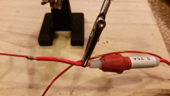
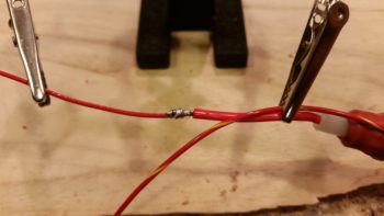
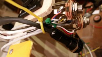
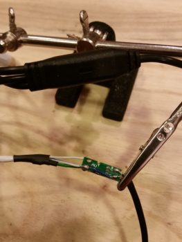
I also engaged in some direct collaboration with Eric Page, ala Aeroelectric Connection forum, on maximizing the output of a Voltage “Deslumpifier” (brown-out circuit module) based on Eric Jones’ (perhiheliondesigns.com … and one of my electrical system mentors) original design.  Initially Eric came back and stated that the specs for his new & improved Deslumpifier design just wouldn’t work for the GNS480.  Then Joe Gore jumped into the forum conversation and sparked an offline discussion between me and Eric on building a supercharged version of his new & improved Deslumpifier, specifically for my GNS480 configuration.  Over the last two days, Eric was able to spec out some higher powered capacitors (5-Farad per) that would both fit his board and give us nearly double the output for my supercharged (in comparison) Deslumpifier.  Of course the proof will be in the pudding if it actually works or not, but based on Joe Gore’s provided numbers, it looks very, very promising… and again, all for much less than TCW’s Intelligent Power Stabilizer (again, not bashing TCW– great products).

So yes, alas, I have gotten very little done in the shop.  But to be honest, I don’t mind straying from the playbook a bit during the cold winter months because it does save a ton of money from having to heat up a cold shop (or try to work layups all under heat lamps). And I have to admit it’s been really gratifying digging deep into these systems and learning their true, no-kidding operational capabilities.


Chapter 22/24 – Off the rails!!!

Today I made a hard right turn in regards to my current tasks to get the cockpit component installs squared away now, so I don’t have to do them later after the install sites are buried underneath top nose foam/glass and/or behind the strakes.

I started off today with the intent of just knocking out wiring up one of micro-video cameras with an extension length of wire (a run to get from the camera which will be positioned just forward of the fuel site gage to behind the instrument panel). Why today, you may ask…. well me digress just a bit:

When I tested out the micro-video camera a few months ago I discovered that the image was definitely clear enough to incorporate for viewing not only of the respective left & right fuel site gages, but also a top camera –mounted in the pilot headrest– looking aft at the engine, prop and top cowling [perhaps a view of the GIB’s face too to ensure they’re ok].  I then decided to add a camera to view the bottom of the aircraft from the nose area looking aft, again to verify all is good down below.

With 4 onboard cameras, I needed (read: “wanted”) a way that I could bring all the cameras’ video lines together into one component to feed the HXr’s RCA-to-USB video input feed device.  I talked to GRT and they stated that their USB video feed device only accepts one input.  Moreover, I wanted my video feed combiner –that feeds the GRT device– to auto cycle through the cameras, showing a video feed for 3-5 seconds on each camera, before moving to the next camera.  Lastly, I wanted to be able to cycle quickly to one of the 4 specific cameras to watch its video.

I posted my question on Bob Nuckolls’ AeroElectic Connection forum and besides Bob himself, got tons of interest on creating a RCA IN-to-RCA OUT video feed device that would control & cycle n number of cameras for 3-5 seconds each (user set), and would be simple to control.  Bob opened up an official project file on this device and two very electronic tech savvy forum members took on the project based on my requirements. Pretty helpful (and cool) to be sure, but at this point the most pertinent part of this story is the two guys honchoing this project need camera, video feed and system data . . . from me.

Now, since I know from UPS tracking that my GRT USB video feed device will be delivered tomorrow, I decided to prep the micro video camera a bit to see if swapping out the typical bulky RCA cord for shielded 2-conduit aircraft grade wiring would work.  However, as is often the case, this is the same wiring that might be required to finish off the Intercom connections . . . ok, long story to state that I felt I should finalize the Intercom wiring –a goal when I started the panel mockup wiring anyway– to figure out how much wiring that I had on hand to use for the micro camera’s video feed test.

So on to the prerequisite intercom wiring, I started off by crimping a D-Sub socket to the end of the Dynon Intercom power wire.

Although I could have done the next step with the wire strippers much easier beforehand, I then used a razor knife to cut away the Tefzel conductor to expose about 1/4″ of bare wire (pic #1 below).

I don’t yet have a Bose noise cancelling headset… yet, but I wanted to go ahead and get the Bose LEMO headset jack wired in with the traditional standard style headset jacks. The Bose LEMO headset jack powers the headset so that you don’t need the bulky battery pack sitting in your lap and in the way [again, not much room in a Long-EZ!).  For the Bose LEMO headset power, I then spliced and soldered an inline fuse holder for a 0.25 amp fuse that is required as per the Bose connector install instructions.  Of course they don’t make ATC fuses (to my knowledge) that small, so I had to go old skool with a glass fuse.

Here’s the final solder splice, connecting the Bose LEMO headset jack input power feed parasitically to the Dynon Intercom’s power wire.

I then spent a few hours, involving 4 batches of printed heat shrink wire labels (around 8 labels per batch) with the majority of those applied, knocking out the wiring connections of on the Dynon Intercom wiring harness D-Sub connector.  Since most of these wires are shielded, it took a bit of time finalizing all these wiring cross-connects.  In the pic below, the Intercom wiring bundled together on the table are the cables for the GIB headset jacks and the COM2 radio.

Regardless, I’m calling the Dynon Intercom wiring harness complete, with some options open for future connections (i.e. remote music jack for GIB, direct EFIS audio input, etc.).

The last push on knocking out the Intercom wiring was to connect the 2 standard headset jacks (phone & Mic/PTT) and the Bose LEMO headset connector.  Besides a power & ground wire, the latter simply ties into the 2 standard headset jacks.

Here’s a bit closer shot of the headset jack wiring.  My soldering won’t win any beauty contests, but it’s definitely good enough to work.

After spending quite a few hours getting the Intercom wired, including power, all the cross connects, and the headset jacks, I finally got to my initial task: wiring up the micro video camera.  I had originally removed the plastic shroud –shown intact on the unmodified camera wiring above my science experiment– covering the mini circuit board that feeds the camera.  While removing this plastic encasement, I nicked the circuit board and cut the thin foil circuit that connects the exterior video feed to the camera video feed.  Thus, when I attached the long aircraft wiring feed to the circuit board, I also had to do a little cross connect wire addition to repair the wayward neanderthal damage I had caused earlier.

When I tested out the extended aircraft wiring connection, the camera was much grainier than the unmodified camera.  Ironically, all the trouble I went through to ensure I had enough shielded wiring on hand was probably for naught.  My instinct is telling me that the shielded cable that I’m using for ground is inducing too much resistance and that I need to try using just regular wire for the ground lead.  Still, I’ll continue to play with it some more to see if I can get the cameras to work using aircraft wiring for the longer leads.

It was getting late and I had yet to make the requisite amount of noise that I usually do in the shop, so I carefully cut out the front top of the left armrest that I had marked the outline of the heating switch panel onto.  I then test fit the armrest in place over and around the now permanently installed heating switch panel, with of course then mandated rounds of sanding, fitting, etc.

I then mounted the cupholder and test fitted the left armrest in place again.  It fits ok, but there is definitely some fine tuning required over the next day or so to get all these components dialed in and playing nicely with each other fit & finish-wise.  Still, this gives you a good idea of the configuration on the front half of my left armrest.

Tomorrow I plan on being back in the shop for most of the day, and then fiddling about with the GRT HXr RCA-to-USB video input feed device later in the evening.


Chapter 22 – Fun’s over…back to work!

I started out today by re-drilling the holes in the pilot seat thigh support CAMLOC receptacle mounting tabs where I had added 2 plies of BID (no pic).  I was ready to install the mounting tabs with CAMLOCs in place, but realized it wasn’t the best idea with only one CAMLOC receptacle on hand.  Obviously I need to order one, so I added it to the small ACS order that I’m compiling.

I then started reviewing what I had left to finish my panel mockup.  With the 2 AG6 warning annunciators, I’ve ridded my panel of all extraneous warning lights save 2 (one red, one green) that specifically are allowed on my panel for the JBWilco Gear & Canopy warning system.  Interestingly, out of all the LED panel assemblies I have in stock, I did not have a green light.  I had the nice Cadillac of LED panel lights that my friend Eric at Perihelion Designs peddles, of which I have a Red & Amber version of, but I don’t have a green.  I went to Eric’s site, but alas I didn’t see them on there (I’m sure even if I missed it he would sell me one).  Interestingly I found Eric’s nice LED assembly on Stein’s site… ok, I had an identified source of supply for my green light!  Check.

So I marked up the panel using the sexy red LED panel light assembly I had on hand … Uh, Houston we have a problem, and it’s space…. not outer space, but space for the fancy robust flange included with Eric’s LED light assemblies.  They could easily fit, but at almost 0.45″ in diameter, they do take up some real estate!

In my quest for a green LED, I did run across Jack Wilhelmson’s Landing Brake switch plate that included a red and green LED… bingo!  Of course I had to rid the LEDs of their soldered component webbed matrix bondage stuff, but after I whittled them all down I ended up with a green and red LED light, albeit with short, solder-encrusted stubby leads. Knowing how these lights look in a panel, plus the diminutive plastic “grommets” used to hold them in the panel, I decided to go with these.  Plus, I really like repurposing stuff that might otherwise just end up in an old parts bin!

I checked Jack’s included landing brake wiring schematic (I’m too lazy to attempt deciphering the resistor color band codes) to determine that he did in fact use a 470 ohm resistor . . . perfect!  Thus, I reused that as well in my evil plan here.  I soldered Jack’s repurposed resistor to Jack’s repurposed green LED.  I then added the appropriate color-coded 22 AWG wire leads by soldering those into place as well.

I then soldered one of my benchstock 470 ohm resistors to the red LED, and also soldered on the appropriate color 22 AWG leads.

While I had the soldering iron fired up & soldering kit ready to go, I knocked out a quick soldering task that I had open on the books: I ridded myself of a big, bulky, heavy and unnecessary deutsch connector that resided on the ground wire to my ElectroAir EIS Controller.   To be clear, in my latest phone call with the ElectroAir bubbas, I specifically asked if this would present any issue: obviously they stated no, the connector was simply in place for ease of installation.  In my case, it would not make installation easier . . .

So, I unceremoniously lopped off each side of the deutsch connector.

I stripped the wires and prepped them for splicing (notice the longer 3-strand “tail” on the top wire).

I then joined the wire together, wrapped the lead (“tail”) around the joined wire bundles to secure the wires together tightly, and then soldered the whole affair.

I then added a piece of heat shrink to finish out my ElectroAir EIS Controller ground wire streamlining . . . Voila!  Aaah, much better.

Unlike my cleaned up ground wire above, my next task was to add complexity to the instrument panel mockup base by creating a mounting frame for the Triparagon, since it’s such an integral part (read: epicenter) to the electrical and avionics systems.

I added a top frame assembly that mimics the F28 bulkhead, including a mounting tab for the Triparagon.  On the forward bottom side I simply screwed a small block of wood in place.  I then slathered on a couple quick coats of white primer to make it all match and let it cure while I was drilling and cutting out mounting holes in the panel mockup.

Quite a few hours later, I brought the dry instrument panel mockup base upstairs, since it was ready to be pressed into service.

I then mounted the Triparagon in place.

Here’s an aft/side shot of the Triparagon.

I then mounted the ELT control head (bottom component on center strut), switches and circuit breakers into the panel mockup.  Right as I was getting ready to mount the panel into the base, I realized I had left out the diminutive Push-to-Test button for the top row Korry lights [I haven’t even address the actual wiring for the GNS480 external Korry light annunciators yet].  So after figuring out it’s exact location, I hauled the panel down to the shop and quickly drilled the mounting hole (with some requisite panel-thinning immediately behind it so it would fit depth-wise).  I then mounted the panel onto the base front uprights.

I then mounted the compass card, GRT Mini-X EFIS, TruTrak ADI, and MGL clock.

I didn’t realize it until much later, but for some reason I inexplicably mounted the MGL clock on the front (outside) of panel vs from the back.  After looking at it for a bit, I realized that I really like it this way.  I will try mounting in the traditional manner and assess, but I am really liking how it looks mounted on the front side of the panel.

I then went offline for a bit panel-wise and had to dig into the Garmin GNS480 unit manual for the details on installing the backplate onto the mounting tube (bracket).  My GNS480 came with the tube and an entire new mounting kit replete with a myriad of tiny screws, washers, etc. to assemble the backplate, D-Sub connectors and antenna connectors.

Once I got the backplate installed onto the mounting tube, I then mounted the tube into the panel mockup.

I then spent the next 2+ hours installing the remaining panel components: GNS480, GRT HXr EFIS, and Korry indicator lights.

I also mounted the 2 LED warning lights that I soldered up previously.  Here’s a shot of just the instrument panel . . . closer to what you would actually see in the plane.

And an even closer shot of the panel components.

Over the next few weeks/months I’ll do all the wiring and cross connects for the panel & Triparagon.  I would like to get it wired to the point that in the next 7-10 days I can fire it up and check out the HXr to ensure all is good with it.  As for now, I’m done with my major digression and will get back to working on the pilot seat area & left pilot armrest console in my continuing quest to finish off the lion’s share of interior cockpit component installs and configuration.  This will of course facilitate closing up the top of the nose and getting the canopy installed.


Chapter 22/24 – ELT mounting base

As I was getting started in the shop I heard the UPS guy drop off my VAN’s O-320 engine baffle kit.  It was another hour before I could collect it up and inventory all the parts.  I know I will have to make both the standard mods to the baffling kit (i.e. trim for EZ cowling), but I’ll specifically have a significant mod in the forward right hand corner where RVs have their oil cooler located.

Still, I’m extremely happy I got this kit since it gets me about 80% there on getting the baffles finished and installed.  (I’d like to recognize and thank Buly again for his tip to go this direction!)

As for the build, I dug out the foam a hair over 0.25″ deep in the area at the bottom left fuselage bulkhead that I had previously “flattened” to allow for the ELT mounting bracket to be installed.

I then traced out the shape, grabbed a piece of H250 foam (to add more strength back into this somewhat critical area) and then trimmed the foam to fit.  The foam piece I grabbed wasn’t big enough so I back filled the corner with a crescent shaped piece.  For all the OCD’ers out there grabbing their inhalers, out of curiosity I just checked the price of H250 on ACS: $175 for a 2’x2′ piece!  The first piece I bought was just under $100 back in 2011, and the second piece less than $120 back in 2013.  So, it’s NOT cheap and I’m not wasting any to make something that’s getting buried in glass look perfect!

Note that you can see the 2 dots I marked up that show the front bolt positions for the ELT mounting bracket.

I then used some spare G10 Garolite pieces I had lying around to make up these 2 forward nutplates for the ELT mounting bracket.  These nutplates will get buried under the uber expensive foam above.

I then marked and cut depressions into the bottom of the H250 foam to allow the nutplates to sit flush.  I then 5 min. glued the nutplates into the H250 foam.  As the 5 min. glue was curing, I then made up a another, narrow 2-nutplate mounting plate out of G10 Garolite.

I then test fitted all my pieces/parts in prep for glassing in the H250 foam into the foam divot I started out making this AM.

After prepping the nutplates by stuffing them with plastic wrap to protect them from nasties, I then flocro’d the H250 foam –with nutplates attached– into place.  I then glassed 1 ply of UNI with the threads running in a nose-to-tail fashion, and then covered that with 1 ply of BID.  I then of course peel plied the layup.

A few hours later I pulled the peel ply, cleaned up and did some judicious sanding on the freshly cured layup.

I then shaped a piece of urethane foam for the aft 2/3rds of the ELT mounting bracket base.  At the very tail end of this aft foam piece will sit the longer, narrow 2-nutplate mounting plate.  I taped up the bottom of the nutplates in this plate, set it in place in the urethane foam and then checked the front bolt marks through the front bolt holes on the ELT mounting bracket.

When the configuration looked good, I then micro’d the urethane foam base in place to the fuselage floor with the ELT mounting bracket set in place on top (to ensure the bolt holes were aligned).  I then slid a 2×4 piece down the center of the ELT mounting bracket, ensuring that none of the bolt holes were covered up (ensuring alignment).  I then placed weights on top of the 2×4.

Here’s another shot.

After a couple of hours, I removed the weights and cleaned up a bit of excess micro that had oozed out.  I then sanded the top of the urethane foam base to match the top angle and elevation of the forward embedded foam base.

After getting a good prep in, I then glassed the aft ELT mounting bracket urethane foam base into place with 1 ply of BID.

During the evening I was able to add a bit to the mockup instrument panel.  If you notice, I redrilled the 2″ hole for the heating vent so that now it is located just above the left armrest intersect point.   I then drilled the holes for 3 switches right above the newly relocated heating vent.  I also drilled and mounted my 2 dimmers (center of center post).

Tomorrow I’ll continue on my quest to get the pilot seat area knocked out.  Now that the lion’s share of effort is out of the way on the ELT mounting bracket base, I can get back to the pilot thigh support seat and get the corner CAMLOCs installed.


Chapter 22/24 – If it pleases the panel

I started off today by pulling the peel ply off of the 7-ply bracket stock, and in turned pulled the bracket stock off of the taped-up 4130 1×1″ square tubing form.  As you can see, it came out just fine.  I just need to sand the inside, trim it up and cut it into individual brackets.

Here’s an end view shot of the 7-ply bracket stock.  Note the CAMLOC that I’ll be using the bracket stock to install.

I had to run some errands, including returning a motorcycle trailer I borrowed from a friend of mine… that took quite a few hours.  When I returned, I essentially spent the rest of the evening figuring out tweaking the component locations on the mockup instrument panel.  I think I’m really getting this panel dialed into where I want it!

I did have to make one major change so far: you can see in the lower left hand side where I filled the 2″ diameter heat vent hole back in by sanding down one of the 2-1/4″ instrument hole plugs that came out when I drilled the upper holes.  I then glued the new 2″ round plug back into place (I wanted to get this done so it would cure overnight).  The reason for doing this is that I decided the switches below the vent need to be higher for easier access, especially since the throttle handle will hinder easier access to that lower area just above the left armrest.

Tomorrow I’ll start back on the ELT mounting bracket and then probably do a lot more on this panel.  I want to get the panel to the point where I can get some serious wiring done in order to power up and check out all the instruments that I have on hand.


Chapter 22/24 – Ribs are done!

Today I started by . . . yep, adding the last bit of dry micro to the last 2-3″ middle area of each micro cap on the pilot thigh support ribs.  These things looked like twins with their shiny micro midsection glaring away, untouched and unspoiled by the thigh support top plate.  So, after sanding the middle micro areas on each each rib top dull, I then whipped up another round of dry micro and applied it.  All in all, I seriously only needed 1/8″ to 3/16″ more micro here, but man this is one of those things in the build that wants to be stubborn!

As the dry micro cured atop my ribs, I got to work finalizing the instrument cutouts for the mockup instrument panel that I’m constructing.  This panel will not only allow me to test instrument, avionic & component placement –and FIT!– but also put them all in their near-final position to allow me to wire them up.

After a few hours I finally saw what I’ve been looking for the last couple of days: no flat or untouched micro atop both my thigh support ribs… yeah!  I started cleaning them up by literally shaving the sides of the overhanging micro like you would a big block of cheese.

Once I got the sides close, I then switched to a sanding block to finalize the sanding of the added micro top.  I may add one more ply of BID just in the center areas for strength, but primarily to keep these from getting chipped away over the years.  Regardless, this part is DONE!

I then tested out the ELT location using the mounting bracket that was included in the ACK E-04 Retrofit kit (read: “starter” kit, IMO) that I just received today [perfect timing!]. The kit also included the panel mounted control head, so I’ll be mounting that in the mockup panel as well.

I also received the Eberhard latch that I’ll be using for the nose hatch.  This is close to the one I saw on Rick Hall’s Cozy IV at Rough River.  I added the wire clamp nut assembly making it pretty much ready for install [Note: I might take the drill to it and drill a few lightening holes since this thing is a bit heavy for its size].  Below the latch is in the hatch closed & locked position.

Here’s the Eberhard nose hatch latch in the hatch open position.

I also cut some uprights for the base of the mockup instrument panel.  I’m making this panel mounting stand a bit taller than just the main instrument panel area to allow for mounting the Triparagon behind the panel, since it plays such a key role in the panel instruments’ wire cross connections.  I went to dinner with my buddy Rob tonight, so before I left I spent about 15 min. painting this base with some white primer to hide all the unsightly water marks and wear on these “trash” pieces of wood that I used.

Tomorrow I plan on continuing with the seemingly unending saga of getting the pilot thigh support top plate installed.  My main task is to get some tabs glassed onto the lower aft side of the instrument panel to allow mounting 2 CAMLOC fasteners that will secure the front side of the seat support plate in place.  I’ll be working on the base for the ELT mounting bracket as well, shaping the fuselage floor to permanently install nutplates to secure the ELT bracket.


Chapter 22/24 – Pile the weight on!

I started out today spending well over an hour doing some research, answering questions, and providing info to Bob Nuckolls, et al. in response to a question I asked on the Aeroelectric Connection forum.  The question I asked was on how to create or modify a 4-into-1 video splitter to channel the micro cameras I’ll have on ship for viewing the back seat left & right fuel site gages, top side looking aft (at engine/prop), and bottom side looking aft (at engine/prop).  This device will then feed a GRT-integrated USB video module that will allow me view the video feeds in a small sub-window on my EFIS either auto- cycling through (that was one of my questions how) or by manual select.

I then got to work on round 2 of the pilot seat thigh support rib tops.  I took the profile of the bottom of the thigh support cover’s underside contour and then cut a cardboard template out so I had a good 1″ wide rib top edge profile to then cut the 1-ply prepregged BID tapes for each side of each rib.

Below you can see I’ve got the 1-ply layups + peel ply on the left rib (bottom) and on the side of the right rib, with the plastic still yet to be pulled.  I know I’ll have to add around 3/16″ -1/4″ more dry micro on top of the existing micro, so I laid up these edge plies of BID so they stuck up above the existing micro a bit.

Once the layups cured for about an hour, I then trimmed them a bit, cleaned them up and then added another round of micro.  I then of course had to add massive amounts of weight to the thigh support cover plate . . . Why?  Because I could …. (grin)

During my shop shenanigans I heard a delivery truck stop by.  A little while later I did in fact find a couple packages on my doorstep.  The first one was from Airflow Performance and had the 90° and 85° air intake elbows that I ordered, with the associated gaskets.

These elbows make up the physical mount and air intake for the air coming out the of Silver Hawk fuel injection servo into the Superior cold air plenum.  In the pic below, the nose of the aircraft would be to the left, prop to the right.  Since all the cold air induction plenums are built for forward facing engines, to incorporate one I had to get my air turned around.

To be clear, this isn’t something I did willy-nilly, although I know a number of Cozy builder/ drivers have done it with reportedly good success.  I conferred with Kevin Murray at Sky Dynamics, my IOX-340S engine builder, Tom Schweitz, and just within the last week I had a good discussion regarding getting this air turned around with Pete at Precision Airmotive, the maker of the Silver Hawk fuel injection system.

I’ve also been discussing this quite a bit with Chris Seats, a fellow Long-EZ builder.  While Chris is not using the Silver Hawk FI (he’s using the EFII system) he is using the Superior cold air induction plenum, so he has to turn the air around as well.  Chris is constructing his own air intake duct out of Carbon Fiber, but was curious about the weight of these combined elbows… which is 1.7 lbs. total.

The other package contained the 2″ high “EXPERIMENTAL” vinyl label that will eventually go on the inside bottom frame of the canopy rail.  It’s kind of hard to tell, but the lettering is simple black letters with a white shadow.  If you’re wondering why I bought this now, remember I had 2 weeks to do nothing but research and figure some of the smaller issues out… so while I had the opportunity I played around with my vinyl decal styles and pulled the trigger on a couple orders.

While my second round of micro on the thigh support ribs cured, I then spent a good amount of time determining the exact location of my GRT HXr EFIS on my panel mock-up blank.  I then cut the PFD mounting hole in the panel and test fit the HXr.

After a gazillion tweaks on the dimensions, trying to ensure every component gets a spot at the (panel) table, I then cut out the mounting hole for the Garmin GNS480 GPS unit that you see “installed” here.

Here’s a shot of the GRT HXr EFIS and GNS480 mounting tube behind the panel.

And another shot of the GNS480 mounting tube.  I’ll have to play around with getting the tube mounted in this panel mock-up blank, since it is a different configuration than how it will actually get mounted in the real panel.

I then spent another couple of hours dialing in the remaining panel avionics, instruments and components.  Since it was too late to do another inevitable round of micro, I left the weights in place on the thigh support cover and hit the rack.  Tomorrow I’ll continue with my primary push to get the pilot’s seat and fuel valve cover completed so I can move on to the left armrest (which, in turn, when finished will allow me to do a final mount of the GIB heating & air ducts).


Chapter 22/24 – Heat & Seat

Today I started out by doing a fair amount of research on my ELT placement, which was why I didn’t want to glass in the outboard thigh support tabs last night.  I’ve planned out my ELT location under the left side of the thigh support, but of course that can change if it doesn’t go in as planned.  I’m installing an ACK E-04 ELT, so I called them today and confirmed the mounting parameters.  I also learned that ACS sells a retrofit kit for this ELT, which is also a “starter” kit with just about everything but the actual ELT module.  I went ahead and ordered the retrofit kit so that I could get my hands on the mounting bracket to install that as early on as possible.

With my ELT info in hand, I then prepregged out another 2 setups of 4 plies of BID + a ply of CF.  I then glassed in the outboard thigh support tabs, placed the cover back on and weighed it down.

Here’s the results a few hours later.

While the outboard thigh support tab layups were curing, I grabbed my 1.25″ thin walled (0.035″) 6061 tubing and cut it in order to make a “T” duct for my heating system.  This “T” duct piece will sit upside down just in front of the left side instrument panel.  The air will flow straight to get to my left foot, and up to get to my upper body (via a vent).

I then entered my data on the online metal calculator, printed off a template, and then taped it to the shorter piece of tubing.

I then used my Dremel Tool to shape the end of the tube.

I then used the shaped tube to mark the longer tube.

I then Dremelled a hole in the longer tube.

My “T” duct fitting is ready to be joined.

With some excess micro, I joined the two pieces of tubing together.  I didn’t glass or rivet it, because these are such light pieces I think micro will do fine to hold them together. Plus, this is also not a critical flight component so I’m more concerned with weight than I am if it happens to break at some point in the future (again, which I highly doubt it will).

I then prepped the tops of both the left & right pilot thigh support ribs.  The task here will be to pile up dry micro and then press it down to the correct height using the thigh support top as a form.  I dug out the foam edges and then vacuumed them, plus all the foam bits scattered all about.

Here’s the whole shebang ready for some micro!

I whipped up a bunch of dry micro –after micro-slurrying the foam edges– and piled it on the top of each thigh support rib.  I then placed the top back on (see a trend here?!) and weighed it down.

A couple of hours later I pulled the pilot seat thigh support top/floor off and was quite surprised at what I found.  The micro was barely touched!  That means A) my ribs are WAY too short! and B) my thigh support top/floor plate is way sturdier than I ever imagined!

So I cleaned up the sides of the micro piles, made them even with the rib sides, and knocked off some rough spots.

I also noted that the epoxy that I had applied to the protective duct tape on the lid wasn’t even touched… I’m still surprised at how low & off these ribs are!

I was wondering a bit on just how to glass the rib sides over the new micro, but now that I have a sense of just how high the ribs need to be (there were a scant few spots of micro that were flattened), I’ll prep the micro first, then glass the sides, then add more micro… tomorrow!  From there, I’ll call it a day on the ribs because I think they’ll be in actual contact and nice and strong.

Another task I did tonight was to cut out an instrument panel blank from a piece of 1/4″ plywood.  I’ll use this as my initial test base for panel instrument placement and wiring.

I also spent a good 45 min working on the placement of my panel components.  Here you can see where I placed the instruments on the back side of the panel.  Also note that I quickly mounted the Triparagon back into place to verify how the instrument panel instruments align with it.

With the Triparagon mounted, I did a quick test fit on the GRT HXr EFIS GADAHRS.  It looks like it will fit in its planned spot nicely.

I then double checked the elevation of the GADARHS unit… also good.

Tomorrow will be more of the same!


Chapter 24 – I’m back! :)

After I got home yesterday from my running around the mid-Atlantic region for the past 2 weeks, I of course had a number of chores to take care of.  I then decided to update some of the build pages on this site, and got prepared for today.  I also caught up with some other builders, read the latest CSA, and did a quick bit of research.

Tonight I wanted to get a quick layup in as a foundation for tomorrow’s build endeavors.  I had originally planned to glass in 3 tabs along the top edge of the front side of the thigh support wedge duct.  However, I decided to wait on the onboard tabs and focus on the middle one.

Why am I putting tabs along the front edge of the wedge duct?  Well, if you think about the original plans pilot thigh support, first of all it’s actually glassed into place. Next, the most common configuration is to either have the thigh support floor/plate/top hinged on the aft side so that it swings up & aft, or at a minimum at least removable and not glassed in . . . so what do these all have in common?  The aft edge of the thigh support floor/plate/top is supported along its entire length.

Mine is not.

So I just want to give a little extra support to the top plate so that it doesn’t balk at me or my pax stepping on it during ingress/egress ops!

Thus, I prepregged two sets of 2 plies of BID and decided to throw another “trash” piece of carbon fiber in the middle for added rigidity, making 5 plies total.  I then wet out the glass, combined my sets into one set with the plies as follows: 2 BID/1 CF/2 BID.  I set it in place, making sure it was high enough on the wedge duct, and then added a little flocro in the corner where it bent back (actually forward) away from the wedge duct.

I then placed the pilot thigh support floor/plate/top in place (with tape on the bottom where it interfaced with the glassed tab). I then weighed down the thigh support floor.

Since I used fast hardener, after a few hours it was cured.  I pulled the weights and then the thigh support floor off the layup and it looked great.  I had peel plied both the face and the front of the support tab, so I pulled the peel ply.

Here’s the center thigh support center support tab in it’s raw form.  I should note that when I laid up the tab in place, the 5-ply glass pad measured 2″ x 2″.

I then did a quick trim on the support tab while the glass was still in its “green” state.

Tomorrow I’ll continue to finalize the installation of the pilot thigh support to then allow me to get on with installing the left pilot armrest & components.


Chapter 24 – Pilot seat floor glassed!

This will be my last build post prior to Rough River!  And since I’ll be on the road visiting folks in North Carolina and Virginia, I won’t be home for another 2 weeks…. so quite the break in build action.

Today I pulled off the boards that I had clamped in place to help straighten out a rather wavy looking foam piece that I shaped into a curve for the pilot seat floor piece, which also happens to make up the majority of the pilot thigh support.

I then cleaned up the initial Kevlar layup and test fitted the floor seat piece without the boards in place.  It looks good, but still needs just a bit more persuasion to be close to spot on.

I also rounded the aft edge into a radius that I assessed as a “pleasing shape” since I plan on doing all glass to glass edges on this seat floor piece.

I then did the round #2 top seat floor layups on both the front and aft side of the piece, overlapping onto the initial Kevlar layup.  The duct tape squares you see in these pics that you might be curious about are 2 pieces of 1.1″ x 1.1″ duct tape plies covered by another 2 plies of just slightly wider duct tape.  These duct tape pads are to provide clearance on the underside of the seat floor piece for the 2 ends of the EFII fuel pump frame that juts aft. The foam over these 2 tape pads, and of course the tape itself, will be removed before I layup the underside of the seat floor.

So, at the outset of the round 2 layups, I set a square of peel ply over each of the duct tape pads and then laid up a 2″ x 2″ ply of reinforcement BID over each of the pads.  I then laid up the separate front side single plies of glass (1 BID & 1 CF) to reach aft enough to cover the tape pads.

Once I got the layups completed and peel plied, I then set the seat floor back in place and clamped it again to try and knock out some of the waviness incurred by heating it up in the curve-shaping process.

You may note that I used some carbon fiber over on the left side.  This is due to the fact that I had some scraps of carbon fiber hanging around, and I also wanted to really lock in that corner and tame an indention over on that side.

A few hours later, when the glass was about 90% cured, I removed the clamps and checked out the layups . . . all good!  Moreover, the slight indention on the left side was in fact tamed and is no longer an issue.

I then pulled the peel ply and cleaned up the layups.  Here’s a test fit of the pilot seat floor after round 2 of the top side layups.

Then it was on to round 3.  I micro slurried what little bare foam was left, and made some transitions (as I had on round 2) with thicker micro between the edges of the Kevlar and the foam.  I also filled in the divot created in the upper right hand corner where the clamp piece of wood made a distinct edge.  I actually liked the depression, but glassing it could have been a bit difficult, so I simply filled it in with dry micro.

I then glassed the second and final ply of BID on the seat floor top.  For some reason I felt like going rogue again and did NOT peel ply the entire layup, just the inside edge that will have a mini wall glassed in around the fuel selector valve.

A few hours later, after the final BID layup on the top of the seat floor cured, I then razor trimmed and cleaned up the edges, and set it back in place for a test fit.  So far I’m really happy with how this is turning out.  To be clear, it’s not perfect, but definitely good enough for this combat builder!

With the top done I got on with the task of shaping the front edges and sides of the underside of the foam seat floor.  Just like the top aft edge, these 3 sides will have a radius that will allow the glass to curve around the edge in one continuous piece to make up the edges of the plate.  Thus, every side of this seat floor plate will have micro’d corners for strength.  This obviously mandated that I had to spend a bit of time making the angled trenches along literally every exterior edge (minus the center U-shaped notch) of the seat floor plate.

I then spent a bit of time as well pulling the tape & peel ply out of the divots I created for the fuel pump frame jut-outs that I needed clearance for.  Once all the remnants of the last bit of “clinging-for-dear-life” peel ply was extracted (with much difficulty at times I might add!) I then used my ever trusty and ever awesome Perm-A-Grit tools to shape the foam edges of the 2 divots.

I should note that although the top was glassed with 2 plies, relatively there is so little mass in the U-shaped notched area that wraps around the fuel selector valve & bracket, that it was surprisingly “flimsy” for lack of a better word.  I decided to reinforce the center narrow area with a patch of BID on the bottom side, but alas I didn’t have any scrap pieces big enough . . . but then again, I did have one last piece of scrap CF hanging around.  I figured CF would provide even greater stiffness here so I threw it on there . . .  at the beginning of the 1-ply BID layup on the underside of the seat floor.  I know it may look a little unorthodox (read: nasty) but in my defense it’s the MGS epoxy’s fault, since if I had used EZ-Poxy you would have never known what it looked like!  hahaha!

Also, before I laid up the final large piece of BID on the underside seat floor, I also again laid up a scrap patch of approximately 2″ x 2″ BID over each divot & overlapping onto the foam to add reinforcement to these glass-to-glass only areas (5 plies of glass total when all is done).

It took a bit of time just to micro slurry the foam face, and then stuff thicker micro all along the mini trenches I had created along all 4 sides.  After the micro went on, to be honest, glassing up the large ply of BID was the EZ part.  However, getting the glass around the corners and sticking to the edges was a bit trickier, but in the end I got it all in place.

A number of hours later, after it all cured, I then razor trimmed the glass, sanded and cleaned up all the edges.

I have to say that I’m ecstatic with how the pilot seat floor plate layups came out!  I didn’t want bare foam on the edges that I would simply have to fill in with micro anyways, since if you’ve seen older plastic airplanes with bare foam edges on parts… well, they look really old, dry and unattractive (I guess that’s what folks say about us ‘ol dog pilots too, eh?!).

Anyway, here’s 3 pics showing the front, aft and side edges of the pilot seat floor plate:

I then of course mocked up the finished seat floor.  Ah, it fits great!

Here’s a closeup shot of the right underside divot where you can actually see the fuel pump frame jut-out (bottom pic) through the glass.  As you can tell, there’s plenty of clearance between the fuel pump frame and the seat floor plate.

Well, nothing left to do on this thing at this point other than try ‘er out!  So I set the seat floor in place, threw a towel and some padding on the pilot seat, grabbed my throttle handle quadrant and climbed in.

This first shot is exactly what I was aiming for!  The fuel selector valve is aft enough and high enough that I can actually easily see it and manipulate it during flight!  Hoo-ah!  Also, I should point out that my fuel selector valve bracket is only about 1/2″ max total farther aft than the stock plans fuel valve plate.  The difference: my valve is located at the very aft end of the plate, obviously about an inch higher, and not located center of mass on the valve plate as the plans valve is.

I then mocked up the throttle location to test it out.  I messed about with the throttle for a bit and determined that for me I had in fact picked the optimum location for this throttle quadrant setup.

Here’s a shot of the throttle handle/quadrant, fuel selector valve and control stick. Again, I’m extremely satisfied with the location, ergonomics and functionality of all these controls!

And here’s my parting shot of this post.  The throttle handle and quadrant in its planned left armrest location.

Again, this will be the last build post for the next couple weeks.  When I get back –renewed, refreshed and re-motivated– I will continue my quest to finish up the internal fuselage component configuration and install before starting on the nose & canopy!