Chapter 22 – More panel stuff

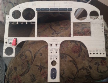
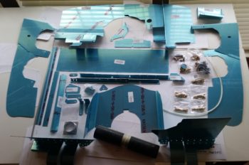
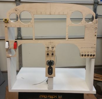
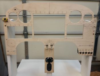
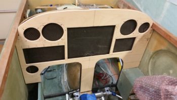
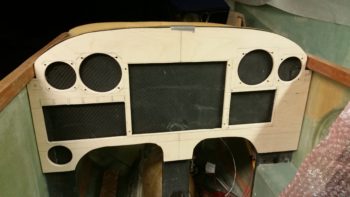
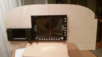
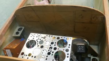
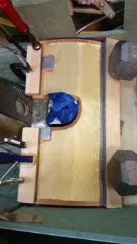
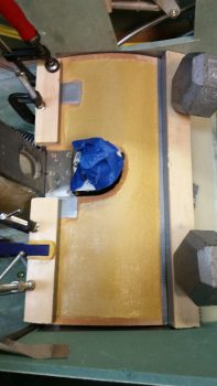
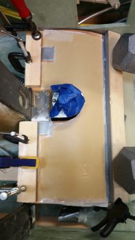
Today was still all about the panel mockup.  With a number of changes I’ve made to the wiring on the back side of the panel, I needed to check those changes to ensure they would fit my design requirements.  Once I determined that I was heading in the right direction, I made the changes which required a fair amount of pulling wires out primarily out of the PQD P6 connector and then re-adding them to other connectors and/or splicing them directly into the Triparagon side wiring.

The main reason behind all this is I had a major rethink on the process of removing the panel.  I had giant brain blank earlier when I didn’t take into account that my removable panel component wiring wouldn’t be routed through one giant opening in the panel, since the current composite “shadow” panel will in most respects mirror the outer 0.063″ 2024 aluminum panel overlay.  This means as wires from each instrument traverses their respective holes to a common connector point, then if I tried to remove the panel after disconnecting that one connector (eg PQD P6), all the wires would get hung up at the connector as the panel was being removed.

Hard to follow?  Think of an octopus on the back side of the panel reaching each of his 8 tentacles through a different hole on the panel. Then think of him grabbing ahold of 8 rods larger than each hole.  You can’t pull the octopus away from the aft panel unless he releases all the rods, and you can’t pull the rods away from the front of the panel without squishing poor Mr. octopus against the back of the panel.  In this scenario though, all the rods (instruments) are attached to the front panel overlay and Mr. octopus represents the panel quick disconnect (PQD) connector, while his tentacles represent the respective wiring to each instrument… hope this analogy makes sense.

Ok, so I removed the PQD P6 connector out of the equation for my MGL Clock, TruTrak ADI, and a few other panel mounted components.  Thus, instead of A→B, B→C, I now simply have A→C with B (P6) cut out of the pic. Of course this change entailed lopping off wiring terminating pins & sockets and then re-terminating the wires by splicing them together.  It also required a fair amount of wire relabeling as well.

My new method of panel removal for these smaller components will be to simply remove the connector at the back of each component.  In the end, it should only add a few minutes to panel removal, and will also allow me a cleaner wiring harness overall since I won’t have as many convoluted wiring runs.

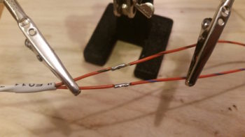
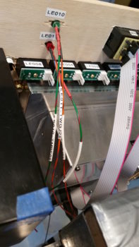
In line with all I stated above, I finished the wiring for the red & green Gear/Canopy warning system wires that I initiated yesterday.  I soldered spliced the wires together for a straight shot from LED light to warning module on one side, and LED light to E-Bus power on the other.  I of course labeled all the wires as well.

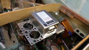
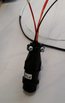
If you recall, I have 3 connectors that make up the Panel Quick Disconnect (PQD) connectors: 24-pin AMP CPC, 37-pin D-Sub, and 15-pin D-Sub.  On the PQD scheme, I switched things up a while back by claiming the 15-pin D-Sub to handle the GRT Mini-X wiring only, while the 37-pin D-Sub handles the GRT HXr wiring only.  However, since I didn’t have enough pins in the 37-pin D-Sub for all the HXr connections, I decided to separate out the 4 power/ground wires and connect them through a mini-Molex connector.

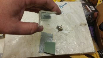
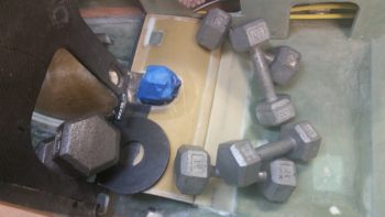
Thus, since the 24-pin PQD P6 connector is an AMP CPC connector, when I pulled the main, secondary, tertiary and ground wires from the P6 connector, I would need to cut off these connectors to re-terminate the wires for the new 4-pin mini-Molex connector. I then remembered that I possibly had a spare 4-pin AMP CPC connector, and after some searching around –Voila!– I did.  I weighed the AMP CPC vs the mini-Molex and the difference was the AMP CPC being 0.08 oz heavier.  With a much better & more robust connection, plus not wasting a couple of dollars in lopped off connectors (which I’ve already had a fair amount of!) I pressed forward with simply removing these wires out of the P6 connector and popping them into my new P7 connector.  So HXr power wires on the Triparagon side are complete.

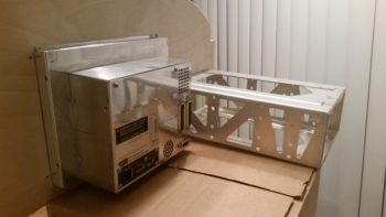
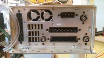
I guess my old military side came out because I then went through and labeled all the D-Sub and antenna connectors on the back panel of the GNS480 GPS unit.

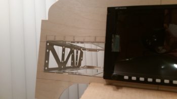
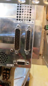
And the back panel of the GRT HXr EFIS.

The moving of wires off of one connector onto another connector, or connecting straight to a wire lead all required a ton of annotations on my connector pinout diagrams.  I have company coming in tomorrow, and a heavy social calendar this weekend, but I will try to get all these changes on my electrical system updated ASAP.  After I get the required adminstrivia updated, then I can get back to actual shop work.

Chapter 22/24 – ELT bracket installed

I started out today pulling the peel ply from the ELT mounting bracket base layup.  I then cleaned up the layup and drilled access holes for my 4 embedded K1000-6 nutplate assemblies.  Finally, I pulled the plastic wrap out of the mounting holes to reveal nice, ready to go screw mount holes.

I then did a test install of the ELT mounting bracket.  All was good except at the front, where the existing floor of the fuselage slanting forward up to, and including, the bottom panel bulkhead lip (the stuff that I cut out to make the ELT sit flat) was physically too close to the mounting bracket and was keeping the mounting clip from getting inserted onto the latch hook.

It took me 3 rounds of cutting, grinding and sanding to finally get it dialed in just enough where I could get the upper latch ring down over the lower latch hook.  With that action, my ELT mounting base is officially installed!

I took a quick shot showing the clearance to the left of the ELT mounting base with the left armrest console sidewall.

I then grabbed my digital level and tested the angle of the ELT mounting base: only 2.9° nose high… I’ll take it!

With ELT mounting bracket “sideline project” out of the way, I started on the final task #3 of my 1-2-3 task list that I ginned up early last week for getting the pilot seat thigh support finished.  In my mind this 3 item list was going to take 2 days . . . and here we are almost a week later!

Anyway, task item #3 is getting a CAMLOC installed in each forward corner of the thigh support top/cover plate (or “floor” as it’s called in the plans).  I rounded up a 3/8″ thick piece of foam that was glassed both sides to mimic my thigh support cover.  I also rounded up the 7-ply glass bracket stock I had made up this past weekend.

I marked the bracket stock to cut out a bracket for the CAMLOC receptacle, which I only have one for testing purposes at this point [NOTE: All my other “CAMLOC” receptacles for the engine cowlings are the SkyBolt variable adjustable type].

I then trimmed the bracket stock and lopped me off a nice bracket from it.

A bit later, here’s my 2 CAMLOC brackets for the pilot seat thigh support, with holes drilled for the receptacles.  As you can see I also grabbed another stud and grommet, which I’m also testing to determine my preference.

I then drilled the stud/grommet thru-holes both left & right in the forward corners of the thigh support cover plate.

Here’s a shot with both stud/grommets in place on the thigh support cover.

I then did some multi-faceted layups.  I started by slathering flocro in the thigh support corner stud/grommet thru-holes (after I prepped the holes by digging out the foam around each hole).  I worked the flocro in nice and good so that it was set inside & past the edges of each hole.

A few hours later I redrilled the thigh support corner stud/grommet thru-holes for nice strong holes with very clean edges.

I needed some more surface area for my thigh support CAMLOC receptacle brackets to mount to, so as part of my multi-faceted layups I used some flocro to mount a couple ~5/16″ thick foam pieces (that I previously shaped) into the upper outboard corners of each of the panel bulkhead’s “map pockets”.  I then glassed patches of BID –2 plies front, 1 ply aft– over these newly inserted corner pieces.

I then peel plied the layups and left them to cure.

A number of hours later I pulled the peel ply and razor trimmed the freshly glassed CAMLOC receptacle brackets’ backplate mounting extensions.

The last bit of glassing I did on the days’ big layup-palooza was to added 2 plies of BID to the top of each thigh support CAMLOC receptacle bracket.  I noted when the CAMLOCs where in the closed/fastened/locked position, that the stud was just slightly proud of the grommet.  I figured 2 plies would get me acceptably closer to a flush stud inside the grommet.  Plus I’ll have paint on the thigh support cover, so I should be able to dial in the depth of the stud to match the grommet on each side.

With my shop work complete for this evening, I then spent over 2 hours working on my mockup/test instrument panel.  I drilled out & jig sawed the 8 holes above the HXr EFIS (PFD) for the Korry status lights, and then another 6 holes above the GNS480 GPS unit for the external GPS annunciator lights (also Korry).

I then spent a good amount of time figuring out where the remaining panel components, mainly switches, will go.

Tomorrow I hope to finish up the pilot seat thigh support CAMLOC install and the instrument panel mockup configuration.  For the panel I’ll probably construct a behind-the-panel cross bracket to mimic the F28 bulkhead so that I can install the Triparagon on the panel mounting base.


Chapter 22/24 – ELT mounting base

As I was getting started in the shop I heard the UPS guy drop off my VAN’s O-320 engine baffle kit.  It was another hour before I could collect it up and inventory all the parts.  I know I will have to make both the standard mods to the baffling kit (i.e. trim for EZ cowling), but I’ll specifically have a significant mod in the forward right hand corner where RVs have their oil cooler located.

Still, I’m extremely happy I got this kit since it gets me about 80% there on getting the baffles finished and installed.  (I’d like to recognize and thank Buly again for his tip to go this direction!)

As for the build, I dug out the foam a hair over 0.25″ deep in the area at the bottom left fuselage bulkhead that I had previously “flattened” to allow for the ELT mounting bracket to be installed.

I then traced out the shape, grabbed a piece of H250 foam (to add more strength back into this somewhat critical area) and then trimmed the foam to fit.  The foam piece I grabbed wasn’t big enough so I back filled the corner with a crescent shaped piece.  For all the OCD’ers out there grabbing their inhalers, out of curiosity I just checked the price of H250 on ACS: $175 for a 2’x2′ piece!  The first piece I bought was just under $100 back in 2011, and the second piece less than $120 back in 2013.  So, it’s NOT cheap and I’m not wasting any to make something that’s getting buried in glass look perfect!

Note that you can see the 2 dots I marked up that show the front bolt positions for the ELT mounting bracket.

I then used some spare G10 Garolite pieces I had lying around to make up these 2 forward nutplates for the ELT mounting bracket.  These nutplates will get buried under the uber expensive foam above.

I then marked and cut depressions into the bottom of the H250 foam to allow the nutplates to sit flush.  I then 5 min. glued the nutplates into the H250 foam.  As the 5 min. glue was curing, I then made up a another, narrow 2-nutplate mounting plate out of G10 Garolite.

I then test fitted all my pieces/parts in prep for glassing in the H250 foam into the foam divot I started out making this AM.

After prepping the nutplates by stuffing them with plastic wrap to protect them from nasties, I then flocro’d the H250 foam –with nutplates attached– into place.  I then glassed 1 ply of UNI with the threads running in a nose-to-tail fashion, and then covered that with 1 ply of BID.  I then of course peel plied the layup.

A few hours later I pulled the peel ply, cleaned up and did some judicious sanding on the freshly cured layup.

I then shaped a piece of urethane foam for the aft 2/3rds of the ELT mounting bracket base.  At the very tail end of this aft foam piece will sit the longer, narrow 2-nutplate mounting plate.  I taped up the bottom of the nutplates in this plate, set it in place in the urethane foam and then checked the front bolt marks through the front bolt holes on the ELT mounting bracket.

When the configuration looked good, I then micro’d the urethane foam base in place to the fuselage floor with the ELT mounting bracket set in place on top (to ensure the bolt holes were aligned).  I then slid a 2×4 piece down the center of the ELT mounting bracket, ensuring that none of the bolt holes were covered up (ensuring alignment).  I then placed weights on top of the 2×4.

Here’s another shot.

After a couple of hours, I removed the weights and cleaned up a bit of excess micro that had oozed out.  I then sanded the top of the urethane foam base to match the top angle and elevation of the forward embedded foam base.

After getting a good prep in, I then glassed the aft ELT mounting bracket urethane foam base into place with 1 ply of BID.

During the evening I was able to add a bit to the mockup instrument panel.  If you notice, I redrilled the 2″ hole for the heating vent so that now it is located just above the left armrest intersect point.   I then drilled the holes for 3 switches right above the newly relocated heating vent.  I also drilled and mounted my 2 dimmers (center of center post).

Tomorrow I’ll continue on my quest to get the pilot seat area knocked out.  Now that the lion’s share of effort is out of the way on the ELT mounting bracket base, I can get back to the pilot thigh support seat and get the corner CAMLOCs installed.


Chapter 22/24 – If it pleases the panel

I started off today by pulling the peel ply off of the 7-ply bracket stock, and in turned pulled the bracket stock off of the taped-up 4130 1×1″ square tubing form.  As you can see, it came out just fine.  I just need to sand the inside, trim it up and cut it into individual brackets.

Here’s an end view shot of the 7-ply bracket stock.  Note the CAMLOC that I’ll be using the bracket stock to install.

I had to run some errands, including returning a motorcycle trailer I borrowed from a friend of mine… that took quite a few hours.  When I returned, I essentially spent the rest of the evening figuring out tweaking the component locations on the mockup instrument panel.  I think I’m really getting this panel dialed into where I want it!

I did have to make one major change so far: you can see in the lower left hand side where I filled the 2″ diameter heat vent hole back in by sanding down one of the 2-1/4″ instrument hole plugs that came out when I drilled the upper holes.  I then glued the new 2″ round plug back into place (I wanted to get this done so it would cure overnight).  The reason for doing this is that I decided the switches below the vent need to be higher for easier access, especially since the throttle handle will hinder easier access to that lower area just above the left armrest.

Tomorrow I’ll start back on the ELT mounting bracket and then probably do a lot more on this panel.  I want to get the panel to the point where I can get some serious wiring done in order to power up and check out all the instruments that I have on hand.


Chapter 22/24 – Prepping ELT install

Today I started off with the main task of installing a CAMLOC in each corner of the pilot thigh support plate, with an associated mounting tab underneath glassed to the lower instrument panel bulkhead.  Well, I quickly realized that to know exactly where the left side CAMLOC mounting was going to reside, I needed to the details of the ELT install.  For example: If the ELT couldn’t be set in low enough under the thigh support, then the CAMLOC assembly might sit too low to allow clearance for the ELT and have to be mounted farther inboard.  Also, if I did install the CAMLOC mounting tab, that’s just one extra extrusion to bloody my knuckles on as I worked on installing the ELT mounting bracket . . . see where I’m going with this?  It’s all sequencing, right?!

Alas, it was time to work on prepping the lower instrument panel and fuselage floor for the ELT mounting bracket.  The ELT is 7.75″ long, so it will extend out from under the seat just a tad, but not enough to get in the way while ingressing and egressing the plane.  I also confirmed with the ACK ELT techs that a “few degrees” up or down is not going to affect proper ELT operation. And to be clear: the manual states that left & right should be no more than 10° off centerline, so for up & down I consider anything less than 10° to be ok (the tech didn’t provide an actual value).

I started the process by marking a channel for the ELT mounting bracket.

I then cut the very bottom of the instrument panel bulkhead, that makes up the bottom cross piece of the “map pocket,”  which I removed right after I snapped this pic.

Then, over a few cycles, I trimmed the glass a little and then sanded the channel in the floor down.  I kept doing this until I constantly got the angle of the ELT mounting bracket to about 3.5° nose high.  I’m definitely going to call that a win.

I have a 3″ x 3″ x 7.75″ cardboard mockup that I made of the ELT.  I tried that out a number of times during the floor channel excavation.  Not one time did I have any clearance issues at the aft end of the thigh support channel.  Actually, if you look in these pics the only issue I had was when I was re-leveling the fuselage at the longerons.  My electronic level fell into the cockpit and put a nice divot in my front seat, then it slammed into the wedge duct top corner and dinged it up pretty good too.

I need to ponder a little more and assess just how I’m going to install the ELT mounting bracket.  I have some ideas, but I wanted to let them germinate a bit before glassing this all up.

Today I also cut 2 small side pieces and the center strut for the mockup instrument panel. I then glued them in place at the bottom of each panel area (L, C, R) with wood glue. An hour or so later I did a quick mock up in the fuselage to see how the mockup test panel compares to the real one.  Looking pretty good!

I also did a number of things with the panel mockup, such as mount it to its base (sorry, no pics… yet).  I also installed the GNS480 mounting tube and test fitted the 480… which installed nicely.

I’ll need some mounting brackets for the CAMLOCs to hold the thigh support cover plate in place, so I took my 1″x1″ piece of 4130 steel and taped it to a glassing board.  I then covered the top and outer edge with a piece of clear packing tape.

Then I laid up 7 plies of glass: 6 BID and 1 UNI, to make up a 1x1x8″ angled composite mounting bracket… which will of course get cut into 8 little mounting brackets.  Once I laid up the glass plies, I of course peel plied the layup.

Tomorrow I have to run some errands and visit some people, so I won’t be back in the shop until the afternoon.  But I do plan on setting the nutplates and glassing in the base for the ELT, and possibly getting a couple of 90° mounting brackets made up and ready for installing the CAMLOCs.


Chapter 22/24 – Ribs are done!

Today I started by . . . yep, adding the last bit of dry micro to the last 2-3″ middle area of each micro cap on the pilot thigh support ribs.  These things looked like twins with their shiny micro midsection glaring away, untouched and unspoiled by the thigh support top plate.  So, after sanding the middle micro areas on each each rib top dull, I then whipped up another round of dry micro and applied it.  All in all, I seriously only needed 1/8″ to 3/16″ more micro here, but man this is one of those things in the build that wants to be stubborn!

As the dry micro cured atop my ribs, I got to work finalizing the instrument cutouts for the mockup instrument panel that I’m constructing.  This panel will not only allow me to test instrument, avionic & component placement –and FIT!– but also put them all in their near-final position to allow me to wire them up.

After a few hours I finally saw what I’ve been looking for the last couple of days: no flat or untouched micro atop both my thigh support ribs… yeah!  I started cleaning them up by literally shaving the sides of the overhanging micro like you would a big block of cheese.

Once I got the sides close, I then switched to a sanding block to finalize the sanding of the added micro top.  I may add one more ply of BID just in the center areas for strength, but primarily to keep these from getting chipped away over the years.  Regardless, this part is DONE!

I then tested out the ELT location using the mounting bracket that was included in the ACK E-04 Retrofit kit (read: “starter” kit, IMO) that I just received today [perfect timing!]. The kit also included the panel mounted control head, so I’ll be mounting that in the mockup panel as well.

I also received the Eberhard latch that I’ll be using for the nose hatch.  This is close to the one I saw on Rick Hall’s Cozy IV at Rough River.  I added the wire clamp nut assembly making it pretty much ready for install [Note: I might take the drill to it and drill a few lightening holes since this thing is a bit heavy for its size].  Below the latch is in the hatch closed & locked position.

Here’s the Eberhard nose hatch latch in the hatch open position.

I also cut some uprights for the base of the mockup instrument panel.  I’m making this panel mounting stand a bit taller than just the main instrument panel area to allow for mounting the Triparagon behind the panel, since it plays such a key role in the panel instruments’ wire cross connections.  I went to dinner with my buddy Rob tonight, so before I left I spent about 15 min. painting this base with some white primer to hide all the unsightly water marks and wear on these “trash” pieces of wood that I used.

Tomorrow I plan on continuing with the seemingly unending saga of getting the pilot thigh support top plate installed.  My main task is to get some tabs glassed onto the lower aft side of the instrument panel to allow mounting 2 CAMLOC fasteners that will secure the front side of the seat support plate in place.  I’ll be working on the base for the ELT mounting bracket as well, shaping the fuselage floor to permanently install nutplates to secure the ELT bracket.


Chapter 22/24 – Pile the weight on!

I started out today spending well over an hour doing some research, answering questions, and providing info to Bob Nuckolls, et al. in response to a question I asked on the Aeroelectric Connection forum.  The question I asked was on how to create or modify a 4-into-1 video splitter to channel the micro cameras I’ll have on ship for viewing the back seat left & right fuel site gages, top side looking aft (at engine/prop), and bottom side looking aft (at engine/prop).  This device will then feed a GRT-integrated USB video module that will allow me view the video feeds in a small sub-window on my EFIS either auto- cycling through (that was one of my questions how) or by manual select.

I then got to work on round 2 of the pilot seat thigh support rib tops.  I took the profile of the bottom of the thigh support cover’s underside contour and then cut a cardboard template out so I had a good 1″ wide rib top edge profile to then cut the 1-ply prepregged BID tapes for each side of each rib.

Below you can see I’ve got the 1-ply layups + peel ply on the left rib (bottom) and on the side of the right rib, with the plastic still yet to be pulled.  I know I’ll have to add around 3/16″ -1/4″ more dry micro on top of the existing micro, so I laid up these edge plies of BID so they stuck up above the existing micro a bit.

Once the layups cured for about an hour, I then trimmed them a bit, cleaned them up and then added another round of micro.  I then of course had to add massive amounts of weight to the thigh support cover plate . . . Why?  Because I could …. (grin)

During my shop shenanigans I heard a delivery truck stop by.  A little while later I did in fact find a couple packages on my doorstep.  The first one was from Airflow Performance and had the 90° and 85° air intake elbows that I ordered, with the associated gaskets.

These elbows make up the physical mount and air intake for the air coming out the of Silver Hawk fuel injection servo into the Superior cold air plenum.  In the pic below, the nose of the aircraft would be to the left, prop to the right.  Since all the cold air induction plenums are built for forward facing engines, to incorporate one I had to get my air turned around.

To be clear, this isn’t something I did willy-nilly, although I know a number of Cozy builder/ drivers have done it with reportedly good success.  I conferred with Kevin Murray at Sky Dynamics, my IOX-340S engine builder, Tom Schweitz, and just within the last week I had a good discussion regarding getting this air turned around with Pete at Precision Airmotive, the maker of the Silver Hawk fuel injection system.

I’ve also been discussing this quite a bit with Chris Seats, a fellow Long-EZ builder.  While Chris is not using the Silver Hawk FI (he’s using the EFII system) he is using the Superior cold air induction plenum, so he has to turn the air around as well.  Chris is constructing his own air intake duct out of Carbon Fiber, but was curious about the weight of these combined elbows… which is 1.7 lbs. total.

The other package contained the 2″ high “EXPERIMENTAL” vinyl label that will eventually go on the inside bottom frame of the canopy rail.  It’s kind of hard to tell, but the lettering is simple black letters with a white shadow.  If you’re wondering why I bought this now, remember I had 2 weeks to do nothing but research and figure some of the smaller issues out… so while I had the opportunity I played around with my vinyl decal styles and pulled the trigger on a couple orders.

While my second round of micro on the thigh support ribs cured, I then spent a good amount of time determining the exact location of my GRT HXr EFIS on my panel mock-up blank.  I then cut the PFD mounting hole in the panel and test fit the HXr.

After a gazillion tweaks on the dimensions, trying to ensure every component gets a spot at the (panel) table, I then cut out the mounting hole for the Garmin GNS480 GPS unit that you see “installed” here.

Here’s a shot of the GRT HXr EFIS and GNS480 mounting tube behind the panel.

And another shot of the GNS480 mounting tube.  I’ll have to play around with getting the tube mounted in this panel mock-up blank, since it is a different configuration than how it will actually get mounted in the real panel.

I then spent another couple of hours dialing in the remaining panel avionics, instruments and components.  Since it was too late to do another inevitable round of micro, I left the weights in place on the thigh support cover and hit the rack.  Tomorrow I’ll continue with my primary push to get the pilot’s seat and fuel valve cover completed so I can move on to the left armrest (which, in turn, when finished will allow me to do a final mount of the GIB heating & air ducts).


Chapter 22/24 – Heat & Seat

Today I started out by doing a fair amount of research on my ELT placement, which was why I didn’t want to glass in the outboard thigh support tabs last night.  I’ve planned out my ELT location under the left side of the thigh support, but of course that can change if it doesn’t go in as planned.  I’m installing an ACK E-04 ELT, so I called them today and confirmed the mounting parameters.  I also learned that ACS sells a retrofit kit for this ELT, which is also a “starter” kit with just about everything but the actual ELT module.  I went ahead and ordered the retrofit kit so that I could get my hands on the mounting bracket to install that as early on as possible.

With my ELT info in hand, I then prepregged out another 2 setups of 4 plies of BID + a ply of CF.  I then glassed in the outboard thigh support tabs, placed the cover back on and weighed it down.

Here’s the results a few hours later.

While the outboard thigh support tab layups were curing, I grabbed my 1.25″ thin walled (0.035″) 6061 tubing and cut it in order to make a “T” duct for my heating system.  This “T” duct piece will sit upside down just in front of the left side instrument panel.  The air will flow straight to get to my left foot, and up to get to my upper body (via a vent).

I then entered my data on the online metal calculator, printed off a template, and then taped it to the shorter piece of tubing.

I then used my Dremel Tool to shape the end of the tube.

I then used the shaped tube to mark the longer tube.

I then Dremelled a hole in the longer tube.

My “T” duct fitting is ready to be joined.

With some excess micro, I joined the two pieces of tubing together.  I didn’t glass or rivet it, because these are such light pieces I think micro will do fine to hold them together. Plus, this is also not a critical flight component so I’m more concerned with weight than I am if it happens to break at some point in the future (again, which I highly doubt it will).

I then prepped the tops of both the left & right pilot thigh support ribs.  The task here will be to pile up dry micro and then press it down to the correct height using the thigh support top as a form.  I dug out the foam edges and then vacuumed them, plus all the foam bits scattered all about.

Here’s the whole shebang ready for some micro!

I whipped up a bunch of dry micro –after micro-slurrying the foam edges– and piled it on the top of each thigh support rib.  I then placed the top back on (see a trend here?!) and weighed it down.

A couple of hours later I pulled the pilot seat thigh support top/floor off and was quite surprised at what I found.  The micro was barely touched!  That means A) my ribs are WAY too short! and B) my thigh support top/floor plate is way sturdier than I ever imagined!

So I cleaned up the sides of the micro piles, made them even with the rib sides, and knocked off some rough spots.

I also noted that the epoxy that I had applied to the protective duct tape on the lid wasn’t even touched… I’m still surprised at how low & off these ribs are!

I was wondering a bit on just how to glass the rib sides over the new micro, but now that I have a sense of just how high the ribs need to be (there were a scant few spots of micro that were flattened), I’ll prep the micro first, then glass the sides, then add more micro… tomorrow!  From there, I’ll call it a day on the ribs because I think they’ll be in actual contact and nice and strong.

Another task I did tonight was to cut out an instrument panel blank from a piece of 1/4″ plywood.  I’ll use this as my initial test base for panel instrument placement and wiring.

I also spent a good 45 min working on the placement of my panel components.  Here you can see where I placed the instruments on the back side of the panel.  Also note that I quickly mounted the Triparagon back into place to verify how the instrument panel instruments align with it.

With the Triparagon mounted, I did a quick test fit on the GRT HXr EFIS GADAHRS.  It looks like it will fit in its planned spot nicely.

I then double checked the elevation of the GADARHS unit… also good.

Tomorrow will be more of the same!


Chapter 24 – Pilot seat floor glassed!

This will be my last build post prior to Rough River!  And since I’ll be on the road visiting folks in North Carolina and Virginia, I won’t be home for another 2 weeks…. so quite the break in build action.

Today I pulled off the boards that I had clamped in place to help straighten out a rather wavy looking foam piece that I shaped into a curve for the pilot seat floor piece, which also happens to make up the majority of the pilot thigh support.

I then cleaned up the initial Kevlar layup and test fitted the floor seat piece without the boards in place.  It looks good, but still needs just a bit more persuasion to be close to spot on.

I also rounded the aft edge into a radius that I assessed as a “pleasing shape” since I plan on doing all glass to glass edges on this seat floor piece.

I then did the round #2 top seat floor layups on both the front and aft side of the piece, overlapping onto the initial Kevlar layup.  The duct tape squares you see in these pics that you might be curious about are 2 pieces of 1.1″ x 1.1″ duct tape plies covered by another 2 plies of just slightly wider duct tape.  These duct tape pads are to provide clearance on the underside of the seat floor piece for the 2 ends of the EFII fuel pump frame that juts aft. The foam over these 2 tape pads, and of course the tape itself, will be removed before I layup the underside of the seat floor.

So, at the outset of the round 2 layups, I set a square of peel ply over each of the duct tape pads and then laid up a 2″ x 2″ ply of reinforcement BID over each of the pads.  I then laid up the separate front side single plies of glass (1 BID & 1 CF) to reach aft enough to cover the tape pads.

Once I got the layups completed and peel plied, I then set the seat floor back in place and clamped it again to try and knock out some of the waviness incurred by heating it up in the curve-shaping process.

You may note that I used some carbon fiber over on the left side.  This is due to the fact that I had some scraps of carbon fiber hanging around, and I also wanted to really lock in that corner and tame an indention over on that side.

A few hours later, when the glass was about 90% cured, I removed the clamps and checked out the layups . . . all good!  Moreover, the slight indention on the left side was in fact tamed and is no longer an issue.

I then pulled the peel ply and cleaned up the layups.  Here’s a test fit of the pilot seat floor after round 2 of the top side layups.

Then it was on to round 3.  I micro slurried what little bare foam was left, and made some transitions (as I had on round 2) with thicker micro between the edges of the Kevlar and the foam.  I also filled in the divot created in the upper right hand corner where the clamp piece of wood made a distinct edge.  I actually liked the depression, but glassing it could have been a bit difficult, so I simply filled it in with dry micro.

I then glassed the second and final ply of BID on the seat floor top.  For some reason I felt like going rogue again and did NOT peel ply the entire layup, just the inside edge that will have a mini wall glassed in around the fuel selector valve.

A few hours later, after the final BID layup on the top of the seat floor cured, I then razor trimmed and cleaned up the edges, and set it back in place for a test fit.  So far I’m really happy with how this is turning out.  To be clear, it’s not perfect, but definitely good enough for this combat builder!

With the top done I got on with the task of shaping the front edges and sides of the underside of the foam seat floor.  Just like the top aft edge, these 3 sides will have a radius that will allow the glass to curve around the edge in one continuous piece to make up the edges of the plate.  Thus, every side of this seat floor plate will have micro’d corners for strength.  This obviously mandated that I had to spend a bit of time making the angled trenches along literally every exterior edge (minus the center U-shaped notch) of the seat floor plate.

I then spent a bit of time as well pulling the tape & peel ply out of the divots I created for the fuel pump frame jut-outs that I needed clearance for.  Once all the remnants of the last bit of “clinging-for-dear-life” peel ply was extracted (with much difficulty at times I might add!) I then used my ever trusty and ever awesome Perm-A-Grit tools to shape the foam edges of the 2 divots.

I should note that although the top was glassed with 2 plies, relatively there is so little mass in the U-shaped notched area that wraps around the fuel selector valve & bracket, that it was surprisingly “flimsy” for lack of a better word.  I decided to reinforce the center narrow area with a patch of BID on the bottom side, but alas I didn’t have any scrap pieces big enough . . . but then again, I did have one last piece of scrap CF hanging around.  I figured CF would provide even greater stiffness here so I threw it on there . . .  at the beginning of the 1-ply BID layup on the underside of the seat floor.  I know it may look a little unorthodox (read: nasty) but in my defense it’s the MGS epoxy’s fault, since if I had used EZ-Poxy you would have never known what it looked like!  hahaha!

Also, before I laid up the final large piece of BID on the underside seat floor, I also again laid up a scrap patch of approximately 2″ x 2″ BID over each divot & overlapping onto the foam to add reinforcement to these glass-to-glass only areas (5 plies of glass total when all is done).

It took a bit of time just to micro slurry the foam face, and then stuff thicker micro all along the mini trenches I had created along all 4 sides.  After the micro went on, to be honest, glassing up the large ply of BID was the EZ part.  However, getting the glass around the corners and sticking to the edges was a bit trickier, but in the end I got it all in place.

A number of hours later, after it all cured, I then razor trimmed the glass, sanded and cleaned up all the edges.

I have to say that I’m ecstatic with how the pilot seat floor plate layups came out!  I didn’t want bare foam on the edges that I would simply have to fill in with micro anyways, since if you’ve seen older plastic airplanes with bare foam edges on parts… well, they look really old, dry and unattractive (I guess that’s what folks say about us ‘ol dog pilots too, eh?!).

Anyway, here’s 3 pics showing the front, aft and side edges of the pilot seat floor plate:

I then of course mocked up the finished seat floor.  Ah, it fits great!

Here’s a closeup shot of the right underside divot where you can actually see the fuel pump frame jut-out (bottom pic) through the glass.  As you can tell, there’s plenty of clearance between the fuel pump frame and the seat floor plate.

Well, nothing left to do on this thing at this point other than try ‘er out!  So I set the seat floor in place, threw a towel and some padding on the pilot seat, grabbed my throttle handle quadrant and climbed in.

This first shot is exactly what I was aiming for!  The fuel selector valve is aft enough and high enough that I can actually easily see it and manipulate it during flight!  Hoo-ah!  Also, I should point out that my fuel selector valve bracket is only about 1/2″ max total farther aft than the stock plans fuel valve plate.  The difference: my valve is located at the very aft end of the plate, obviously about an inch higher, and not located center of mass on the valve plate as the plans valve is.

I then mocked up the throttle location to test it out.  I messed about with the throttle for a bit and determined that for me I had in fact picked the optimum location for this throttle quadrant setup.

Here’s a shot of the throttle handle/quadrant, fuel selector valve and control stick. Again, I’m extremely satisfied with the location, ergonomics and functionality of all these controls!

And here’s my parting shot of this post.  The throttle handle and quadrant in its planned left armrest location.

Again, this will be the last build post for the next couple weeks.  When I get back –renewed, refreshed and re-motivated– I will continue my quest to finish up the internal fuselage component configuration and install before starting on the nose & canopy!


Chapter 24 – Airplane baker man!

I started out today by pulling the peel ply and cleaning up the pilot thigh support ribs. I also cut out the glass from the mouse hole on the aft side of the right rib along with the overhanging glass from the layups.

I then trimmed the bottom of the right armrest to provide clearance and eliminate any rubbing on the fuel lines.

I also notched the bottom center of the left pilot armrest with a triangular opening to allow the armrest wall to fit over the pilot thigh support wedge duct when installed.  I also had to narrow the thickness of the wall on the outboard side of it that was adjacent to the air vent plenum duct in order for it to fit in its planned location.

I then got to work on shaping the pilot thigh support seat floor.  First, I copied the thigh support rib profile onto a template.  Then I used the template to mark up a scrap piece of OSB chipboard to cut out 4 thigh support rib jigs.

I then cut out the pilot seat thigh support floor piece from 3/8″ foam, and then clamped the 4 thigh support rib jigs to the bottom of the floor piece.

I then baked the jigged & clamped pilot seat thigh support floor piece in the oven for an hour at 280°.  In hindsight, it may have a been a bit too long to bake it, but in my defense there was no bake time listed in the plans!

I had to run out for a while after I turned the oven off and the floor piece started cooling down.

When I returned, I noted that there was a bit of waviness in the front & aft edges of the floor piece since the heating of the foam apparently produced some sagging in between the clamped rib jigs.  Moreover, these “scalloped” edges were significant enough that I thought about scrapping this floor piece and remaking another one.  But I don’t like wasting foam and to be honest, I kind of like the challenge of fixing a piece that’s less than perfect and make it work.

I pressed forward with the floor piece install and started working it until it proved to be unworkable, to see if it would . . . but it didn’t.

I wanted to lock in the CORRECT floor piece profile, so I decided to do a multi-part layup starting on the top of the floor piece surface (plans has you layup the bottom surface first). Since I needed to clamp both the front and aft edge to lock in the correct shape, I further decided to start with a large central ply of Kevlar –specifically to add puncture strength to a piece that gets stepped on every ingress & egress of the plane– and then add a strip of BID on both the front and aft edges after the center area floor piece profile was better locked into shape.  After these first pieces are laid up, I’ll of course lay up a ply of BID over the entire top surface of the floor piece.

As for the Kevlar layup, I started out by microing the surface of the floor piece top where the Kevlar ply will get laid up.

I then set the ply of Kevlar in place on the top of the pilot seat floor piece.

I then wet out the Kevlar.

And then peel plied the Kevlar layup.

Tomorrow I’ll continue to glass the pilot seat seat floor piece in my attempt to both get it installed, but also to straighten out some of the front and aft edge waviness that was introduced during my heating of the floor piece foam plate.  Still, I think it should be fine.