Chapter 22 – Introducing: The X-Bus!

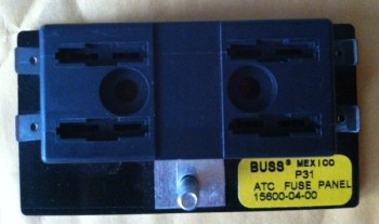
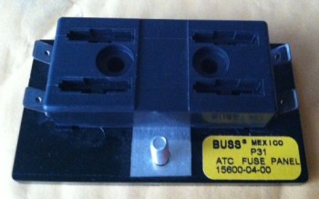
I mentioned in my previous post that I created a new mini-buss to facilitate power handling and circuit protection for my Integrated Back-up Battery System (IBBS) that’s depicted on WireBook Drawing #15: IBBS.  Here’s a closeup shot of the new mini-bus, that I’m sure by now that you’re aware that I have affectionately dubbed it the “Extended Buss,” or X-Bus for short.  And if you’re wondering what all the hoopla is about, all I can say is, “Hey, com’n … this is the first electrical buss I’ve ever created!” 

Chap 22 - X-Bus

You may also remember that I mentioned I was able to grab one of these babies–the same make & style as my other 3 busses from B&C–off of eBay for around $10.  Here is the actual 4-gang ATC fuse holder that I bought off of eBay.

Chap 22 - X-Bus

Behold, the new X-Bus!

Chap 22 - Extended Buss (aka "X-Bus")


Chapter 22 – More Electrical Subsystems

Over the past week I’ve continued on in my quest to complete all my wiring diagram pages for my wiring book before I leave the Middle East here within about 6 weeks!  Once I return to the states, pull my Long-EZ build out of stasis, and start sniffing epoxy fumes again I won’t have the forced luxury of time (unless I take time off from actual building) to get down into the weeds of each subsystem–electrical & otherwise–that I’ve been able to do while separated from my actual project.

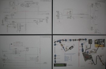
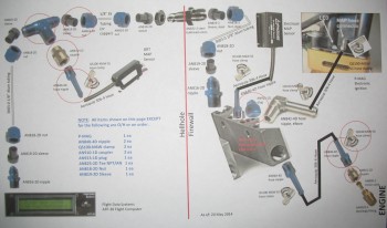
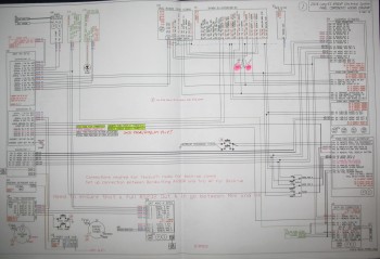
Over the past week I’ve completed the Integrated Back-up Battery System (IBBS), the Charging System, and the Landing/Taxi/Nav/Strobe/Wigwag Lights System electrical diagrams.  Also, within hours of posting last week’s MAP & Vacuum system diagram, I found during a relook at the installation instructions that my GRT MAP Sensor was mounted on the wrong side of the firewall: the hot side.  Unlike the Electroair MAP sensor, which is fine on the hot side of the firewall (and that’s exactly where the builder is told to install it), the GRT MAP sensor must be on the cold side of the firewall.  Although I had ordered the majority of the connectors, I found during my redesign that I would still use all that I ordered, so for the project manager in me it felt good to know I hadn’t wasted any (more!) money on the stuff I did order.  Like last week, in the pic below I show the 3 newly completed wiring diagrams and my updated hack Manifold Pressure system PowerPoint diagram.

Chap 22 - Electrical System

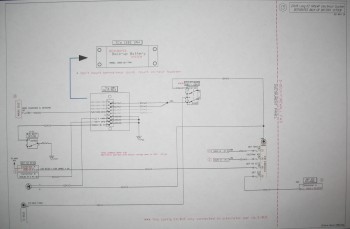
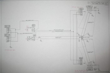
Below is a shot of my Integrated Back-up Battery System (IBBS) wiring diagram page. Note that TCW’s new 3AH IBBS is the backbone of my back-up battery system.  Also, a long time issue that I had was exactly how to wire up my panel components to have them on back-up power during engine starting (thus not having to power them down during start), but also provide current protection and the ability to switch them between IBBS power and E-bus power at will.  I guess this is the power behind subsystem diagrams, because after drawing it all out, reviewing the install manual & my past communications with Bob at TCW, I was able to see that I needed to create another mini-buss to solve my issue.  The new mini-buss is a 4-gang ATC fuse holder ($10 off eBay with shipping!) and is exactly the same make as my other buses.  I call the new mini-buss my Extended Buss, or X-Bus for short.  The X-Bus works perfectly in allowing me to fulfill all my design criteria for my IBBS:

Chap 22 - Electrical System

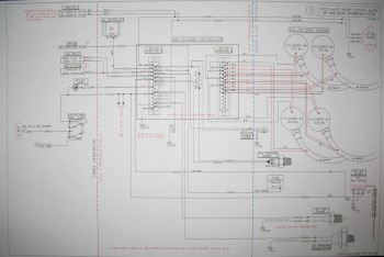
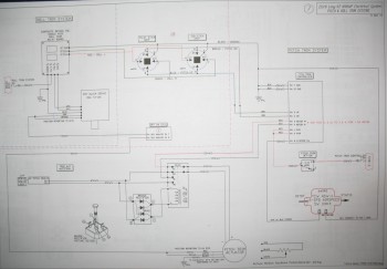
Here’s a shot of my Landing/Taxi/Nav/Strobe/Wigwag Lights System wiring schematic:

Chap 22 - Electrical System

Below is the updated list that I shared last week (again, green denotes completed or mature, yellow is currently being worked):

Z.  Z-13/8 Electrical System
–    Switch Configuration
1.  Panel Components
2.  Radio & audio system
3.  Main Bus
4.  Batt Bus
5.  E-Bus
6.  Nose Gear
7.  Pitch & Roll Trim Systems
8.  Lights: LDG, TAXI, NAV, STROBE
9.  Engine Info Management
10. Fuel System
11. Cockpit Lighting
12. Landing Brake
13. Throttle Switches
14. Control Stick Wiring
15. Integrated Back-up Battery System
16. Alarm & Warning Systems
17. Charging System
18. Heater System
19. Electronic Ignition
20. P-Mag Ignition
21. Component Interconnects
22. Starting System

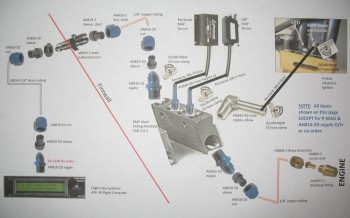
And finally, here’s another shot of my upgraded Manifold Pressure system design:

Chap 23 - MAP System


Chapter 22 – Electrical Subsystems Wire Books

In the past week I’ve completed a few more wiring diagram pages for my wiring book: the Electroair electronic ignition, the P-MAG ignition and the Engine Info System (GRT EIS4000).  In addition, I took quite a few hours to sit down to figure out what components I needed for my Manifold Pressure & Vacuum system design.  In the pic below I show the 3 newly completed wiring diagrams and my hack PowerPoint diagram that I made to keep track of all the bits n pieces required to build the Manifold Pressure system.

Chap 22 - Electrical & Chap 23 - Engine

Here is a shot of my Engine Info Management wiring diagram page:

Chap 22 -Electrical System

Along with knocking out some wiring diagrams, I also added a couple more diagrams to the list of subsystem diagram pages for the Wiring Book.  I broke out the Starting system to its own page, and to keep track of all the wiring and to have a holistic, systemic, wire-focused (vs component-focused) view of my system, I added a Components Interconnect page.  Below is the updated list that I shared last week (again, green denotes completed or mature, yellow is currently being worked):

Z.  Z-13/8 Electrical System
–    Switch Configuration
1.  Panel Components
2.  Radio & audio system
3.  Main Bus
4.  Batt Bus
5.  E-Bus
6.  Nose Gear
7.  Pitch & Roll Trim Systems
8.  Lights: LDG, TAXI, NAV, STROBE
9.  Engine Info Management
10. Fuel System
11. Cockpit Lighting
12. Landing Brake
13. Throttle Switches
14. Control Stick Wiring
15. Integrated Back-up Battery System
16. Alarm & Warning Systems
17. Charging System
18. Heater System
19. Electronic Ignition
20. P-Mag Ignition
21. Component Interconnects
22. Starting System

Here is a shot of my professional quality PowerPoint (ha!) showing my Manifold Pressure system design:

Chap 23 - Manifold Pressure System


P-MAG it is!

In creating my Electroair Electronic Ignition wiring diagram and digging down into the weeds of it all, I kept coming across an issue that on the surface might not seem that difficult to fix.  And honestly, perhaps it’s not for some folks.

So let me give a little background.  For my ignition system I had planned to install an Electroair electronic ignition system in lieu of one Slick magneto on one side, but still go with a Slick magneto on the other side.  I had talked at length with Kevin at Sky Dynamics and few other engine gurus on simply replacing the Slick mag with a P-MAG when that dreaded “500” hour mag overhaul came due.  They understood the economy of using what was available and cheaper in the near term, but going with a much better solution in the long run.  In short, the feedback was that it wasn’t a bad plan.

This ignition configuration then became my plan for quite a while.  However, in my recent focus on this system, I’ve run across a couple of things threw a wrench into my planning process.  The final result though, is a more optimized install and system anyway, IMO.

First, after talking to a couple builders and reading a few accounts of swapping a magneto out for a P-MAG, or any other electronic ignition, probably made my statement, “Oh, I’ll just swap out the mag for a P-MAG” maybe just a bit too simplistic.  Can it be done?  Certainly. And of course it’s not an insurmountable job.  The problem though really comes down to space & access.  There is simply not a whole lot of room between the engine accessory case & the firewall in an EZ.  Again, it doesn’t place the swap-out in the realm of the impossible, I’ve just heard (most recently from my buddy Dave Berenholtz) that it’s a real PITA!  And I don’t know about you, but I try to avoid PITA situations as often as possible!

Second,  I had planned on using the Slick mag side of my ignition to start the engine, then flip the Electroair EI ON once the engine was going.   The issue here becomes a little multi-faceted.  Slick mags of course come in two flavors: Impulse & Non-impulse. Impulse mags are used to start the engine, while non-impulse mags are used as just a redundant ignition system to get juice to the spark plugs.  In an attempt to make my future P-MAG install as painless and pre-readied as possible, I would need to use a non-impulse mag in order to NOT have to pull the impulse mag innards and also still be able to reuse the non-impulse drive gear (‘cuz it costs a bit).  Well, in order to use a non-impulse mag, I would need to use the Electroair EI side to start the engine.  No problem, the Electroair EI works great and can be used as the engine starting ignition if that’s how I wanted to configure my ignition system.

While researching the feasibility of using the Electroair as the starting ignition, and how to do it, I ran across a potential issue.  Apparently, some Electroair users have had starting issues when the bus voltage is too low, caused by anything from a battery issue to cold weather.  Moreover, these issues were popping up (NOT in overwhelming numbers mind you) in RVs and Glastars, not just canards.  In my mind, with such a long power run between the battery in the nose and starter/EI at the tail end that we have in canards, this configuration could very well exacerbate any propensity for this type of scenario to occur.

The solution?  Throw a small 1.3AH battery in the circuit and call it a day.  Simple enough eh?  But how exactly does this work?  And now I’m throwing more weight and complexity at the issue.  I contacted Electroair to see if this was in fact a good idea to have a power boost for engine starting to avoid such potential nasties as kickbacks & simple non-starts. They said it was & gave me a generic solution for running a battery in parallel with my starting circuit.  Since my back-up battery system is TCW, I contacted Bob there and asked him about it.  Of course Bob isn’t an Electroair guru, so he also gave me a generic solution.  The bottom line is as I tried to work this solution, I kept going back to my original specific design goal for all of this: to use the cheaper Slick Mag solution as long as I could, then swap it out for a P-MAG after it essentially died on the vine.  Now, quite often I’m just not that bright, and it sometimes takes a while for a solution to sink in.  But hey, if my ultimate goal is to have a P-MAG installed anyway, and by having it installed it eliminates all my current design & planning woes…. WOAH, WAIT A MINUTE!!!  HA!

Chap 23 - P-MAG Ignition

If you’re a Cohen brothers fan, and you’ve seen the movie, The Hudsucker Proxy, then you’ll understand that maybe this blog post should have been titled, “The Future is Now!” 

Thus, I stopped all the madness, all the silliness, all the hand-wringing, and started listening to ECi, Kevin at Sky Dynamics, Nick Ugolini, Dave Berenholtz, et al by simply deciding to go with the P-MAG solution from the git-go and dump any ideas of saving money with the Slick Mag solution.



Chapter 22 – Electrical System Diagrams

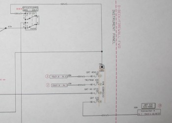
I have been working on my Electrical System since September of 2012.  More recently, over the last 6 months, I’ve been trying to get it as close to finalized as possible before I head back to the States… and commence to start building in earnest.  One goal that I had while being separated from snorting epoxy fumes and getting touchy-feely with itchy fiberglass for the past year of this build was to complete my electrical system wiring book. I want a solid plan to follow once I get to the point of wiring up this bird, and I don’t want to be in a position of trying to design my wiring system as I install it, or worse, take precious time away from actually wiring the plane to research out what I’m supposed to do, or how to do it.  Of course, my overall goal is to have a very optimized, efficient and as Bob Nuckolls would put it, “elegant” electrical system (all that equaling ‘safe’ too!).

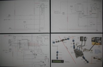
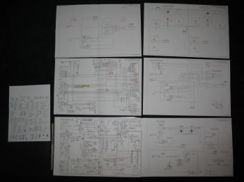
Pic below shows Switch page (L side) and Z13-8 Main Electrical System diagram (Lower L) along with five other electrical subsystem diagrams.

Chap 22 - Electrical System

Of course another reason for me to document my electrical system & wiring, and the foundational research that goes into all that, is to have reference documents to go back to in case something just ain’t working right!

So a couple of months ago I felt my electrical system was to the point where I should start diagraming out the electrical subsystems. Thus, over the past couple of months I’ve started in on the individual pages–one for each subsystem–of the Wiring Book.  Below is the ever-expanding and ever-morphing list of subsystem diagram pages for the Wiring Book (Green denotes completed or mature, yellow is currently being worked):

Z.  Z-13/8 Electrical System
–    Switch Configuration
1.  Panel Components
2.  Radio & audio system
3.  Main Bus
4.  Batt Bus
5.  E-Bus
6.  Nose Gear
7.  Pitch & Roll Trim Systems
8.  Lights: LDG, TAXI, NAV, STROBE
9.  Engine Info Management
10. Fuel System
11. Cockpit Lighting
12. Landing Brake
13. Throttle Switches
14. Control Stick Wiring
15. Integrated Back-up Battery System
16. Alarm & Warning Systems
17. Charging & Starting Systems
18. Heater System
19. Electronic Ignition
20. P-Mag Ignition

The wiring pages for the individual busses (#s 3-5) will be created last after all the minutia is flushed out and sorted through for each subsystem.  It’s amazing the amount of research, emails, and phone calls, etc. that goes into creating each subsystem diagram. Of course, it’s an understandable dynamic that more companies producing components for homebuilts gear them towards the RV crowd, simply because that’s arguably the most often built experimental in el mundo.  Unfortunately, this can create issues for us Canardians as we fervently try to cram RV-oriented electrowhizzies into our prized EZs. Also, it’s simply a matter that a lot of these smaller companies just haven’t got around to engineering a solution between their and other products that can work in our canards.

A good example of this is when I had to contact both TCW and Trio to figure out how to get the Trio A/P AutoTrim function to work with TCW’s SafetyTrim Pitch Trim Controller.   Both companies were of course fantastic, but it took a good day and a half to work out and confirm a solution.  And that’s for just a few wire connections between two devices. Clearly most of us have a fair number of electrowhizzies in our birds, and luckily most of this stuff is figured out ahead of time . . . but definitely not all the time!
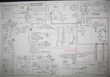
Below is a shot of my main wiring diagram for the Z-13/8 electrical system architecture that was developed by Bob Nuckolls from The AeroElectric Connection fame.  I have of course taken the basic diagram and modified it countless times for my purposes.  If you are building an airplane and don’t have this book, get it!  I seriously don’t know how you could wire an experimental airplane without it.

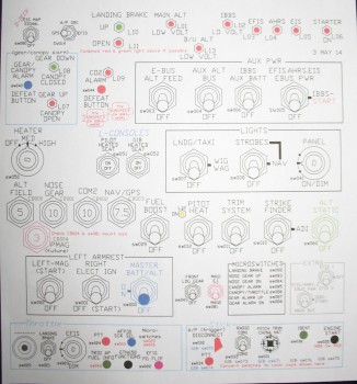
Chap 22 - Electrical SystemHere below is a shot of my switches, circuit breakers, and LED lights diagram.  Notice that each device is numbered with a specific code.  These codes are depicted wherever the device shows up on any given wiring diagram.  They’re also annotated on a spreadsheet that I keep all these device codes in, and will be incorporated into a wiring identification schema which will be labeled on each wire.  Once the labels are on the wires, I’ll be able to look at any wire and its associated 12-digit code, tell exactly what device the wire is coming from and from what area (nose, engine compartment, etc) of the aircraft, what device and area it’s going to, and its function.
Chap 22 - Electrical System

Below is a working copy of my panel wiring diagram.  I spent nearly a week working off & on to upgrade the diagram so it depicted the Garmin GTN650 pinouts vs the Garmin GNS430W.

Chap 22 - Electrical System

And finally, here’s a shot of the Pitch & Roll Trim Systems wiring diagram:

Chap 22 - Electrical System


Chapter 21 – Capacitance Fuel Probes

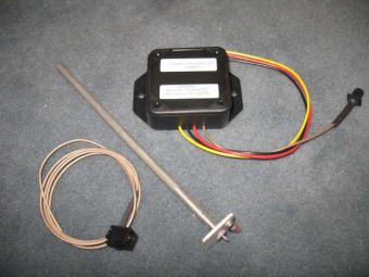
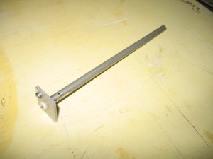
This afternoon I was able to get a hold of Master Canardian Nick Ugolini and order a set of his Capacitance Fuel Probes.  Nick designed the probes himself to be used in canards and to link up to Princeton Fuel Probe electronics to provide high quality fuel reporting to EFISs, etc.

Chap 21 - Capacitance Fuel ProbesAt first I resisted the idea of fuel probes since I already have Vance Atkinson’s fuel site gauges and will be using a fuel flow sensor.  But considering that these are just a few ounces a piece including the electronic control boxes, I figured knowing my exact fuel quantity for a total weight penalty of well under a pound was worth it.  In addition, I had just read too many reports extolling high praise for this system to ignore them all and not pull the trigger on a set. (I pulled the pics below off of Nick’s blog):

Chap 21 - Capacitance Fuel ProbesAnother motivating factor for installing these probes early on (i.e. during the build) is that since I’m gearing up in the planning and R&D of my strake-building, it just makes sense that they’re a heck of a lot easier to install now during the initial strake construction vs. changing my mind and installing them after my strakes are all closed up.  Now, that being said, they actually don’t look to be that difficult to install after the strakes are built, but anything I can do to avoid introducing potential contamination–in the way of bits & chunks of foam & glass, etc–into my fuel system is worth doing early on.
Chap 21 - Capacitance Fuel Probes


Chapter 17 – Pitch Trim Update

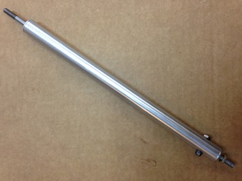
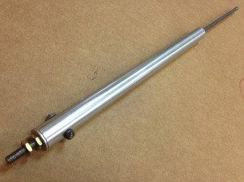
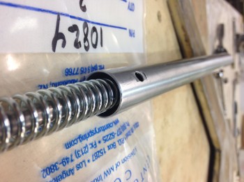
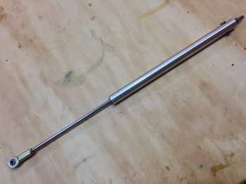
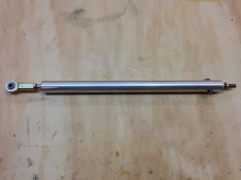
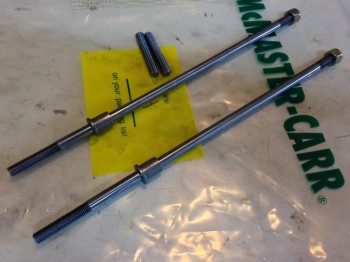
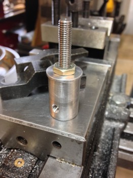
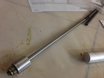
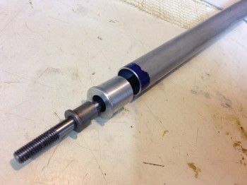
The Atkinson Pitch Trim System project marches on!  After receiving new parts and materials, Marco has machined some simply beautiful spring housing assemblies. Which, speaking of springs, they seem to be the most problematic part of this whole endeavor.

Chap 17 - Atkinson Pitch TrimChap 17 - Atkinson Pitch Trim

When Vance designed and built this pitch trim assembly back in the 1990’s, apparently both True Value and Ace hardware stores carried a spring known as “Compression Spring p/n 196.”  Well, after emailing, calling and perusing a half-dozen True Value and Ace hardware stores–and those big Blue and Orange guys as well–for those of you that are interested, I can assure you that that spring is no longer in their inventory.  Nor anything close to it to serve as a suitable substitute.

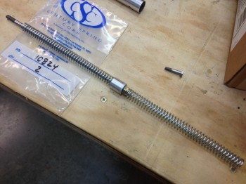
However, after one Amazon & two Century Spring Co. orders for springs (I won’t bore you with Century Spring’s minimum order amount), it looks like we finally found a suitable spring, and possibly one viable candidate . . . subject to testing of course.

Chap 17 - Aktinson Pitch TrimChap 17 - Atkinson Pitch TrimNow that we have a viable set of springs, and can use those specs to narrow in our search for some springs that let us lock in our control forces (FYI – Vance had three sets of springs [that fit!] that he tried out before getting the right “feel” on the pitch controls).

Chap 17 - Atkinson Pitch TrimChap 17 - Atkinson Pitch TrimIn addition, I’ll be ordering the actuator this week so that at least initial testing can begin, which will help in selecting some further spring candidates.


Chapter 22 – Instrument Panel Ongoings

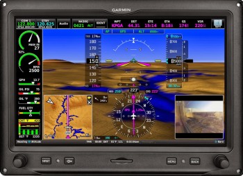
Chap 22 - Garmin G3X Touch

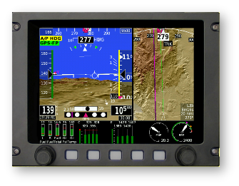
After squawking about the new Garmin G3X Touch being too expansive for my wee panel, I decided that I should thoroughly investigate it to ensure I wasn’t missing anything important.  So this past weekend I again built a matrix to compare all my EFIS options to ensure that I’m getting the best capabilities, cost benefits, and of course weight efficiency out of my EFIS that I possibly can.  Thus, I did a runoff betwixt the new Garmin G3X Touch, threw the close-sized GRT HXr 10.4 back into the mix, the GRT HX 8.4, and GRT HX 6.5.

Chap 22 - GRT HXr 10.4 EFISChap 22 - GRT HX EFIS

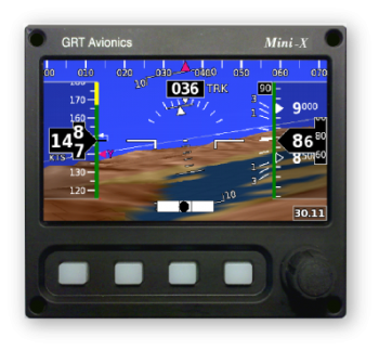
I then began to tally up all the weight, cost & current draw of all the components required to give me the capabilities I’m looking for in an EFIS system.  Something to note that in all of these configurations is that the second-screen MFD and back-up PFD is the GRT Mini-X.

Chap 22 - GRT Mini-X EFIS

I was surprised as I tallied up the prices that the cost difference between the Garmin G3X Touch and the GRT HXr was less than a grand.  As I trudged along in looking up component weights, and with things still looking comparable between the two systems (of course giving a slight performance edge in touchscreen simplicity to the Garmin), I hit a fairly significant snag.  It appears that Garmin’s remote transponder is a robust bubba, weighing in at over 3.4 pounds with an installation depth of over 11 inches. The weight on this one transponder helped get me back to reality, realizing that I was comparing the big heavy guys, when once again I was getting plenty of capability with the smaller, very capable “little guy” EFISs that were much lighter and offered much more panel space … and thus configuration options.  So once again, although tempted by cool colors and touchscreens, I dumped the big EFISs to return to smaller, lighter and more efficient.

One thing that came out of my EFIS comparison, was that I took a hard look at my allowable space BEHIND the instrument panel.  I pulled out the plan’s A-pages to measure out clearances and I had a true Doh! moment.  Albeit initially (Fall 2012) I had been verifying clearances behind the panel with cardboard mockups, since then I had been rearranging, adding, removing and modifying my avionics/instruments with apparent reckless abandon!  The result was that I was placing components in position on the front panel with assumed clearance behind the panel.

To remedy my ways, I gathered the physical data for the displays, avionics, instruments and components all going into the panel.  I clearly needed to deconflict my behind-the- panel space requirements to match what I could have on the front of the panel.  I will say that I attribute this epiphany in part to Nick Ugolini since I found while reviewing his blog that he had run into this snag while redoing his instrument panel.

A significant focus in this effort is of course the area immediately behind the lower right side panel, since the elevator control rod must have free reign in its movements.  I had stacked up my GNS430W/GTN650 over on the right side, having failed to verify it’s clearance with the elevator control rod, and then even added a couple of other rather deep instruments to boot.  I’m glad I found it now, but I admit it was not the most optimized planning on my part.

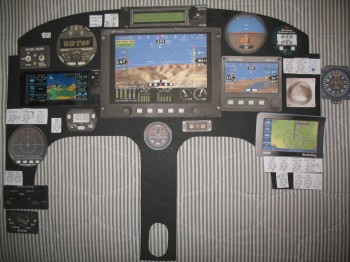
The result of all this was a trip back to the proverbial drawing board.  I got out my cardboard cutouts and begin putting all the “new” puzzle pieces in place.  The result is something along the lines of this:

Chap 22 - Instrument PanelAgain, I will make note that this is still a work in progress, but at least now I am very cautious about my specific clearances behind the panel.  In the back of my mind I thought I was doing this, but pulling out the actual plans verified and confirmed how little space there actually is behind our panels in these birds.  And of course we all know what assumptions get us!

Build on!


Chapter 22 – Electrical & Avionics Banalities

So I’ve been working on my electrical system. I upgraded my electrical system diagrams from a Garmin GNS430W to the GTN650. I figure by the time I buy my main Nav GPS I won’t be wanting technology that’s on Garmin’s eventual chopping block for support. Of course with the move to the GTN650, I had to add two more Circuit Breakers to the panel since it’s a mandatory requirement for them that you use CBs and not fuses. Although admittedly two CBs for 7 wires is not bad.

I’ve also been spending some time on my throttle and stick (HOTAS) switches.  I reconfigured a number of switches between panel, throttle and stick, and in doing so was able to get rid of a couple panel switches.

Right now I’m thinking that if one has the panel real estate that the new Garmin G3X Touch is the way to go. As for me, I’m not burning that much real estate for an EFIS display. I decided that quite a while ago when I made a decision to forego the 10.4″ GRT HXr PFD for GRT’s much more manageable 8.4″ or 6.5″ PFD. Plus, as awesome as Garmin is, those bubbas tend not to play well with others’ stuff. I guess it’s a good marketing strategy, but picking up and using cool & useful third party stuff with Garmin can be problematic if ‘Big Brother G’ simply says, “No, you can’t use that crap with our suite of technological goodies! Here, use this nice GARMIN thing X instead!”

Also, now that I’m getting significantly closer to my final instrument panel and electrical system configuration, I’ve started building all my Wire Book templates.  I have about 20 total templates currently completed for all the various electrical subsystems, and I’ve built 5 system diagrams from these templates so far.  It should be slow steady progress over the next few months since each one that I build helps with building the remaining ones.

Chapter 17 – Atkinson EZ Electric Trim System

Since January I’ve had an ongoing email conversation with Vance Atkinson about his venerable EZ Electric Trim System.  Vance’s pitch trim system is similar in a vein to the Strong pitch system in that it acts both in a linear motion, and some what parallel to the control inputs… or at least much more oblique than a Davenport leaf spring pitch trim system.  From what I’ve read though, and not having personally flown behind any of them, the Strong system has had both good and bad reports.  The Davenport system seems to get high marks, but it’s significantly heavier and in my configuration would need to be mounted on the center instrument panel leg post, and I want to free up that space for other components while of course saving weight.  Moreover, the Atkinson pitch trim system uses an aircraft quality actuator and the spring assembly is made of aircraft grade metals.

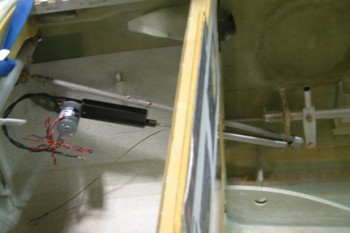
Below is a picture of Bernie Siu’s Atkinson pitch trim system that he installed in his Cozy. As can be seen, the trim assembly mounts out of the way on the side of the fuselage just forward of the panel, and connects to the elevator control rod via rod end.  Bernie has a great detailed explanation of his experience with both the Strong and Atkinson systems here.

Chap 17 - Atkinson Pitch Trim

So, after some discussions with my building buddy Marco, we decided to pull the trigger and make a couple of these guys.  As per usual, I provided the financial backing and he provided the talent!  (ha!)  I ordered the materials and hardware required for two of these suckers and had it all sent to Marco’s production shop of magic and wonder.

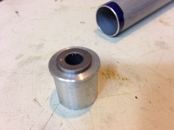
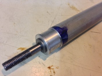
Not surprisingly, within short order (mere minutes most likely!) of receiving the required stuff, Marco had worked his machinist’s magic on his lathe and mill to give us the beginnings of two beautiful Atkinson EZ Electric Trim Systems.

Chap 17 - Atkinson Pitch TrimChap 17 - Atkinson Pitch Trim

Chap 17 - Atkinson Pitch TrimChap 17 - Atkinson Pitch TrimChap 17 - Atkinson Pitch TrimChap 17 - Atkinson Pitch Trim

Of course, once again, Marco has done some masterful work and produced some amazingly beautiful machined pieces!   (Bravo my friend!)