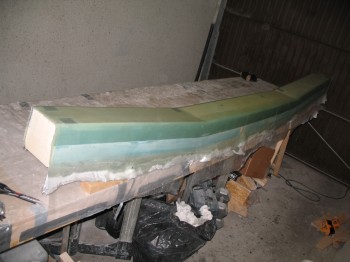
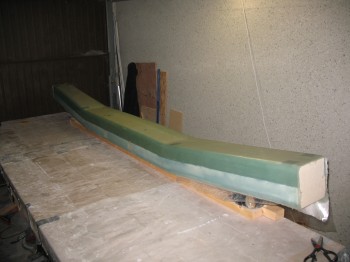
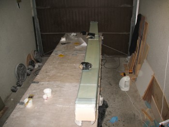
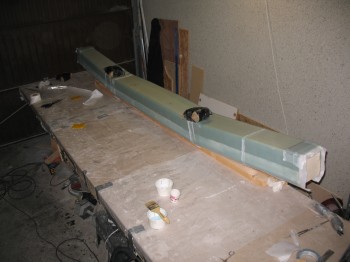
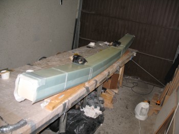
Chapter 14 – CS spar… final steps

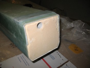
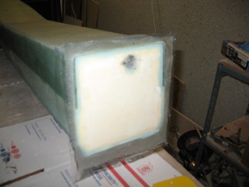
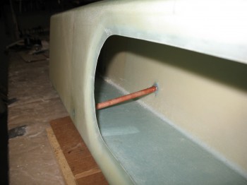
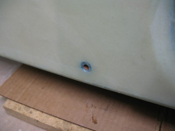
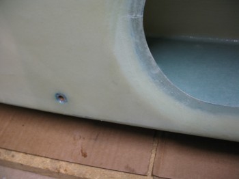
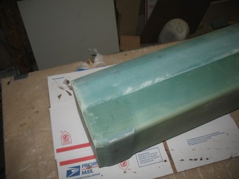
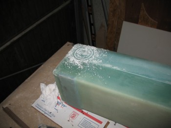
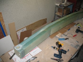
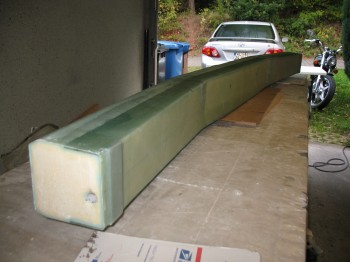
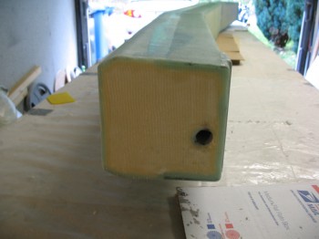
I started off today by installing & floxing into place the phenolic tubing that will be the conduit for the Nylaflow rudder cable conduit as it traverses the CS spar front & aft walls.

Chap 14 - CS spar rudder cable conduit

Again, I’d like to reiterate that these holes were created in the glass layups on both the inside & outside walls by carefully separating the glass fibers so that they went AROUND the holes.  No glass (or shall I saw the minutest amount) was cut or drilled to install this phenolic tubing.

Chap 14 - CS spar rudder cable conduitChap 14 - CS spar rudder cable conduit

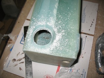
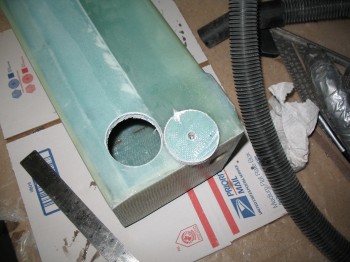
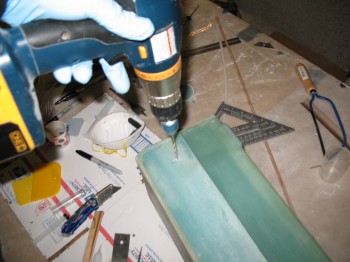
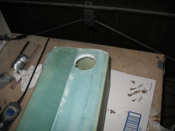
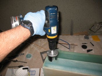
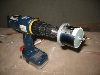
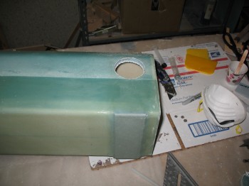
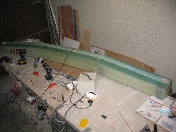
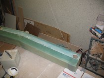
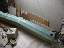
I then measured out & drilled a 2-1/4″ hole (approximately, I was using German hole saw bits so it was ~57mm) on each end of the spar on the bottom to allow access to the wing spar bolts.

Chap 14 - Spar bolt access holeChap 14 - Spar bolt access holeChap 14 - Spar bolt access holeChap 14 - Spar bolt access holeChap 14 - Spar bolt access holeChap 14 - Spar bolt access hole

After I drilled the holes, I Dremeled out the foam just a bit along the edge of the hole, cleaned everything up, and then dry micro’d the edges of the hole.

Chap 14 - Spar bolt access holeChap 14 - Spar bolt access holeChap 14 - Spar bolt access holeIMG_0014Chap 14 - Spar bolt access hole


Chap 22 – Electrical & Chap 21 – Fuel

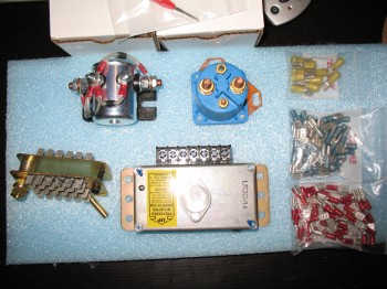
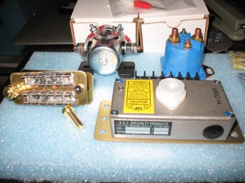
Tonight I took some pics of some of my electrical components that I received from B&C Specialty Products.

Pictured below is the master battery contactor (silver), the starter contactor (blue), the firewall ground “forest of tabs,” and the B&C LR3C 14v Voltage Regulator.  As well as an assortment of FastOn terminals.

Chap 23 - ElectricalChap 23 - Electrical

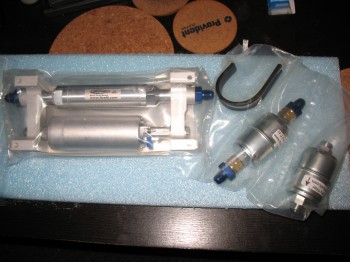
And below is the EFII Electric Fuel Boost Pump with filters that I recently received from ACS.

Chap 21 - Fuel System

Chapter 14 – CS spar end caps

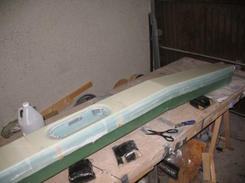
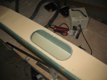
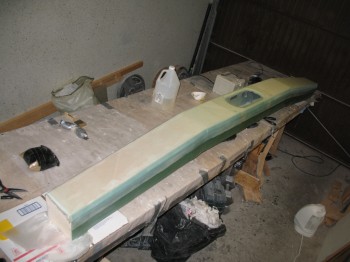
Today I started by using the Fein saw (again, I call it that for ID purposes, but mine is actually a cheapo version from Harbor Freight… but it works great!) to remove the overhanging glass on each end of the spar & on the straight runs of the oval access hole.

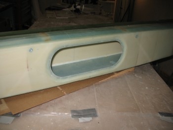
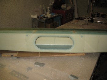
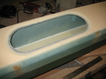
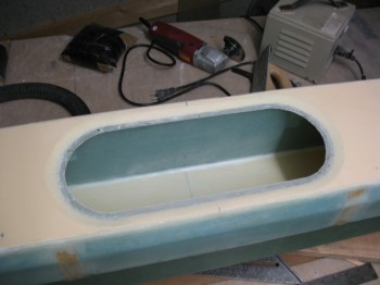
I then focused on the oval access hole with the Dremel tool.  I knife trimmed it as well to remove all the excess/overhanging glass.  I also used my Perma-Grit tool and sandpaper to smooth out the access hole edge and surrounding glass.
Chap 14 - CS spar end caps

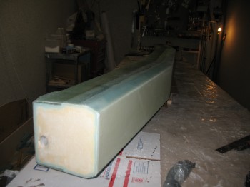
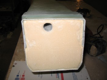
I used a 7/8″ bit to drill out the foam covering the electrical wire/antenna cable conduit at each end of the spar.  I sanded it to round over the edge of the hole for a nice radius.

I then Dremeled out a narrow wedged-shaped channel into the foam at each end of the spar around the inside edges of the glass.  I removed the foam on the inside of the glass to maybe 1/4″ deep max.
IMG_0002Chap 14 - CS spar end caps

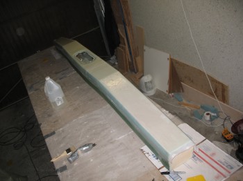
I sanded the foam faces at each end of the spar, vacuumed the end bulkhead surfaces & prepped for glass.

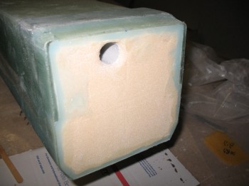
First, I cut 2 pieces of 7.5″ x 7.5″ of BID at a 45° bias.

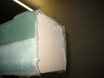
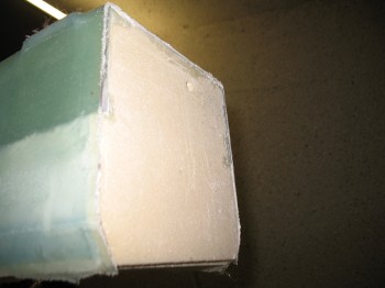
Then I floxed the edges of the glass into the channels I had just created in the foam.  What this does is create a fillet in the corner between the existing 4 sides of the glass & the newly laid glass.  Once it cures, there will be a very solid “triangular” (as best possible) corner bead that will greatly increase the strength of the corner, and also the bulkhead’s glass ply covering.
Chap 14 - CS spar end capsChap 14 - CS spar end caps

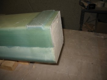
I micro’d the remaining foam in the middle of the end bulkheads.  I then wet out the pre-pregged 1-ply of BID…. which is hard to see with only one ply.  I then glassed each end of the spar with the 1-ply BID pre-pregged layup.
Chap 14 - CS spar end capsChap 14 - CS spar end caps

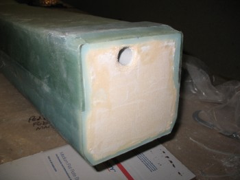
I trimmed the excess glass with my Dritz scissors (still awesome!) & then made an X-cut in the glass over the hole and plugged each one so the glass would wrap around the radiused edge of the hole and cure securely onto the interior of the channel conduit.
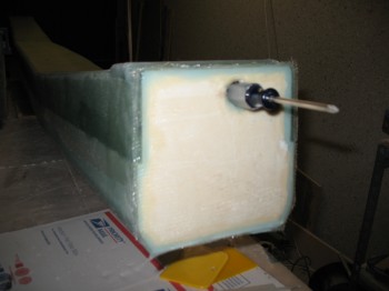
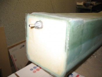
Chap 14 - CS spar end capsChap 14 - CS spar end caps


Chapter 14 – CS spar final side glassed

I started off today by refilling some more hardener & consumables.

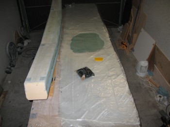
I cut 11-1/2″ wide UNI strips across the full length of the roll at 45° . . . enough for a 2-ply layup across the front face of the CS spar.  I also cut an 11″ x 22″ 1-ply BID piece at a 45° bias for reinforcement around the center spar access hole.

I had a couple delams right along the edge of the angled/wedge corner … apparently I didn’t squeegee it well enough and gravity did it’s work & it separated just a hair.  I quickly gave it an injection of epoxy.

I used a flox/micro mix for the edge & edge divots.  I also added some flox around the edge of the hole as a base layer since the glass was thin but still a bit rough from how it had cured before.

Chap 14 - Glassing final sideChap 14 - Glassing final side

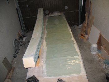
I glassed Layup #8 (2-ply UNI ± 45° … so 90° angle to each other).  As I laid up the glass, I very carefully separated the glass fibers around the holes for the rudder cable conduit, just as I had done with the glass on the back of the spar.

Chap 14 - Glassing final side

Chap 14 - Glassing final side

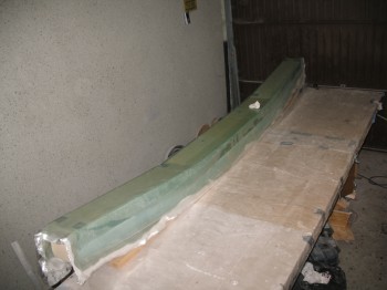
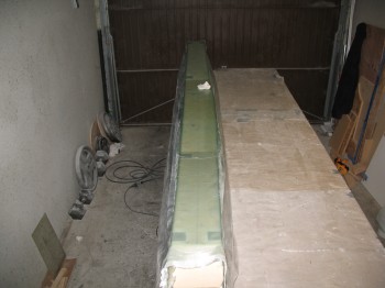
I glassed the 1-ply BID around the the oval access hole & then peel plied the entire layup.

Chap 14 - Glassing final sideChap 14 - Glassing final side

Chap 14 - Glassing final sideChap 14 - Glassing final side


Chapter 14 – CS spar prep for final glass

I started today by refilling the slow hardener bottles & cleaning the Dritz scissors.

I then removed the peel ply from the CS spar, cleaned up & removed the peel ply strings & goobers from the layup.

Chap 14 - CS spar build

I used the Fein saw to cut the glass flush at the CS spar end.

Chap 14 - CS spar buildChap 14 - CS spar buildChap 14 - CS spar build

After cleaning up the end glass on the spar, I removed it from its 2×4 mounts.

Chap 14 - CS spar buildChap 14 - CS spar buildChap 14 - CS spar buildChap 14 - CS spar build

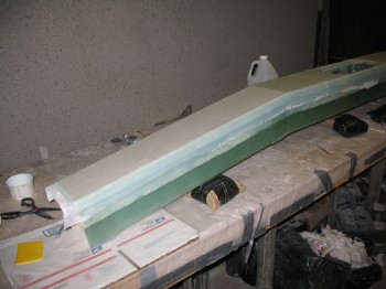
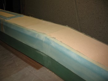
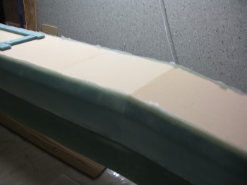
I again used the Fein saw to trim the glass along the top & bottom edges (at the angled/wedged corner) so it was close to the foam.  I hit the edges with a hard sanding block as well.

Chap 14 - CS spar build

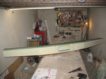
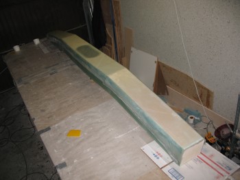
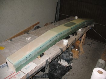
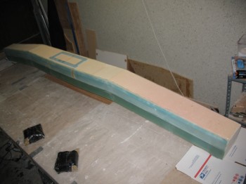
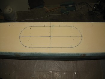
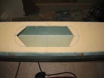
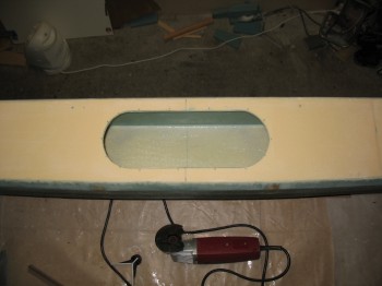
I cut the 5″ x 14″ oval access hole on the front face of the CS spar.

Chap 14 - CS spar buildChap 14 - CS spar buildChap 14 - CS spar buildChap 14 - CS spar build

I removed the peel ply at the edge of the oval hole & sanded a beveled transition around the cutout.
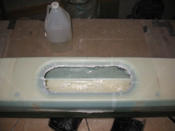
Chap 14 - CS spar buildChap 14 - CS spar build

I then sanded the entire front face & Dremeled out any dead micro & epoxy.
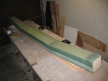
Finally, I vacuumed the entire spar & the surrounding work bench.


Chapter 14 – One big layup!

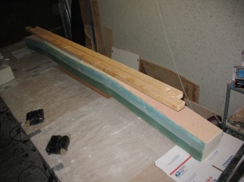
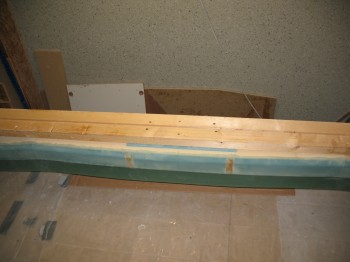
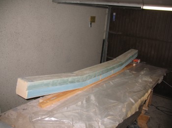
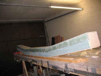
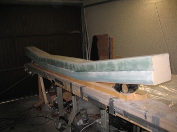
I started off today by mounting two long 2×4’s to the middle of the 5″ x 14″ oval access panel.

Chap 14 - Mounted glassing base

I used 3″ long drywall screws & the nice part is that it’s drilled to glass that will simply get removed and chucked.

Chap 14 - Big layup #6

Chap 14 - Big layup #6

I laid out the plies of UNI & cut plastic for the pre-preg.

Chap 14 - Big layup #6Chap 14 - Big layup #6

I micro’d the foam with both dry micro & microslurry.  I then wet out the pre-pregged UNI.

Chap 14 - Big layup #6Chap 14 - Big layup #6

I then laid up the pre-pregged UNI glass onto 3 sides of the spar: top, aft & bottom.  This is the plan’s Layup #6.

Chap 14 - Big layup #6Chap 14 - Big layup #6Chap 14 - Big layup #6Chap 14 - Big layup #6

I cut the edges on each side close to the 1/2″ x 1″ wedge cutouts on the front corners of the spar.

I then floxed 2 each LWA3 aluminum extrusions & 2 each LWA3 aluminum extrusions on top of the existing Inboard & Outboard extrusions.  I covered the LWAs with the UNI & BID plies that I cut on 24 Sep.

I then peel plied the entire layup & weighed down the Inboard extrusions.

Chap 14 - Big layup #6Chap 14 - Big layup #6Chap 14 - Big layup #6

Chapter 14 – No go

I set up the heaters today to get the garage/workshop ready for the big layup #6 glassing, but I couldn’t get it heated past 62°F.

So I pre-deployed the cut glass to the garage & decided to wait until Saturday to do the big layup (so I could glass during the day while the weather is obviously the warmest).

Chapter 14 – Glass Cuttin’

Today I cut 2 sets of the Outboard UNI extrusion caps:  3″ wide x 12″, 14″, 16″ long.

I also cut 2 sets of the Inboard UNI extrusion caps: 3″ wide x 8″, 10″, 12″ long.

Finally, I cut 2 sets of BID for the final Outboard extrusion layup glass ply (5″ x 6″) and 2 sets for the final Inboard extrusion layup glass ply (5″ x 8″).